EP0443360B1 - Garniture de frein pour freins à disque à garniture partielle avec disque de frein, spécialement de véhicules ferroviaires - Google Patents
Garniture de frein pour freins à disque à garniture partielle avec disque de frein, spécialement de véhicules ferroviaires Download PDFInfo
- Publication number
- EP0443360B1 EP0443360B1 EP91101483A EP91101483A EP0443360B1 EP 0443360 B1 EP0443360 B1 EP 0443360B1 EP 91101483 A EP91101483 A EP 91101483A EP 91101483 A EP91101483 A EP 91101483A EP 0443360 B1 EP0443360 B1 EP 0443360B1
- Authority
- EP
- European Patent Office
- Prior art keywords
- brake
- brake lining
- disc
- circular ring
- perforation
- Prior art date
- Legal status (The legal status is an assumption and is not a legal conclusion. Google has not performed a legal analysis and makes no representation as to the accuracy of the status listed.)
- Expired - Lifetime
Links
- XLYOFNOQVPJJNP-UHFFFAOYSA-N water Substances O XLYOFNOQVPJJNP-UHFFFAOYSA-N 0.000 claims abstract description 22
- 238000011109 contamination Methods 0.000 claims description 3
- 238000009423 ventilation Methods 0.000 claims description 3
- 238000010276 construction Methods 0.000 claims 1
- 239000000356 contaminant Substances 0.000 abstract description 3
- 239000002245 particle Substances 0.000 abstract 1
- 230000000717 retained effect Effects 0.000 abstract 1
- 230000000694 effects Effects 0.000 description 6
- 238000005299 abrasion Methods 0.000 description 4
- 238000004140 cleaning Methods 0.000 description 2
- 239000002783 friction material Substances 0.000 description 2
- 238000010521 absorption reaction Methods 0.000 description 1
- 230000002411 adverse Effects 0.000 description 1
- 239000011230 binding agent Substances 0.000 description 1
- 239000002131 composite material Substances 0.000 description 1
- 230000005494 condensation Effects 0.000 description 1
- 238000009833 condensation Methods 0.000 description 1
- 238000010586 diagram Methods 0.000 description 1
- 238000005562 fading Methods 0.000 description 1
- 235000015243 ice cream Nutrition 0.000 description 1
- 238000007373 indentation Methods 0.000 description 1
- 210000003734 kidney Anatomy 0.000 description 1
- 239000000463 material Substances 0.000 description 1
- 230000008092 positive effect Effects 0.000 description 1
- 230000003313 weakening effect Effects 0.000 description 1
Images


Classifications
-
- F—MECHANICAL ENGINEERING; LIGHTING; HEATING; WEAPONS; BLASTING
- F16—ENGINEERING ELEMENTS AND UNITS; GENERAL MEASURES FOR PRODUCING AND MAINTAINING EFFECTIVE FUNCTIONING OF MACHINES OR INSTALLATIONS; THERMAL INSULATION IN GENERAL
- F16D—COUPLINGS FOR TRANSMITTING ROTATION; CLUTCHES; BRAKES
- F16D65/00—Parts or details
- F16D65/02—Braking members; Mounting thereof
- F16D65/04—Bands, shoes or pads; Pivots or supporting members therefor
- F16D65/092—Bands, shoes or pads; Pivots or supporting members therefor for axially-engaging brakes, e.g. disc brakes
-
- F—MECHANICAL ENGINEERING; LIGHTING; HEATING; WEAPONS; BLASTING
- F16—ENGINEERING ELEMENTS AND UNITS; GENERAL MEASURES FOR PRODUCING AND MAINTAINING EFFECTIVE FUNCTIONING OF MACHINES OR INSTALLATIONS; THERMAL INSULATION IN GENERAL
- F16D—COUPLINGS FOR TRANSMITTING ROTATION; CLUTCHES; BRAKES
- F16D65/00—Parts or details
- F16D65/0037—Devices for conditioning friction surfaces, e.g. cleaning or abrasive elements
-
- F—MECHANICAL ENGINEERING; LIGHTING; HEATING; WEAPONS; BLASTING
- F16—ENGINEERING ELEMENTS AND UNITS; GENERAL MEASURES FOR PRODUCING AND MAINTAINING EFFECTIVE FUNCTIONING OF MACHINES OR INSTALLATIONS; THERMAL INSULATION IN GENERAL
- F16D—COUPLINGS FOR TRANSMITTING ROTATION; CLUTCHES; BRAKES
- F16D69/00—Friction linings; Attachment thereof; Selection of coacting friction substances or surfaces
-
- F—MECHANICAL ENGINEERING; LIGHTING; HEATING; WEAPONS; BLASTING
- F16—ENGINEERING ELEMENTS AND UNITS; GENERAL MEASURES FOR PRODUCING AND MAINTAINING EFFECTIVE FUNCTIONING OF MACHINES OR INSTALLATIONS; THERMAL INSULATION IN GENERAL
- F16D—COUPLINGS FOR TRANSMITTING ROTATION; CLUTCHES; BRAKES
- F16D69/00—Friction linings; Attachment thereof; Selection of coacting friction substances or surfaces
- F16D2069/004—Profiled friction surfaces, e.g. grooves, dimples
Definitions
- the invention is based on a brake lining for partial brake disc brakes with a brake disc, in which water drainage devices are provided on the front side opposite the rear side and provided for contact with the brake disc of the disc brake, for which purpose the brake lining is spaced apart from one another by a number the front of the brake pad continuously extending to the back, for receiving and removing friction-preventing dirt such as water, ice, abrasion or the like. suitable openings are provided.
- a brake pad is provided in particular for rail vehicles and, if necessary, is provided with a dovetail guide for a pad carrier on a rear side.
- Such a brake pad is known for example from DE-U-89 05 731.
- the two ends of a brake lining existing surfaces are divided into several straight partial areas, which extend over the entire area of engagement of the brake pad on the brake disc and which form an angle alpha of less than 90 ° to the friction surface of the brake disc.
- brake pads are more or less dimensionally stable today and the edge surfaces are at an angle of 90 ° to the friction surface of the brake disc.
- a brake pad for partial brake disc brakes is already known, which is formed in one piece, water drainage devices are provided on the opposite side and provided for contact with the brake disc of the disc brake, for which purpose the brake pad with itself from the Front of the brake pad continuously extending to the back, to absorb friction-preventing dirt, such as water or the like. suitable openings are provided.
- a brake lining for partial brake disc brakes with a brake disc in particular of rail vehicles, which is optionally provided with a dovetail guide for a brake disc carrier on a rear side, water drainage devices being provided on the front opposite and provided for contact with the brake disc of the disc brake , with the brake pad facing at least one from the front of the Brake lining continuously extending to the back, for receiving and removing friction-preventing dirt such as water, ice, abrasion or the like.
- Suitable openings are provided, provided that the pad is one or more parts and approximately circular segment-shaped and that according to a 1st alternative as a minimum on the front of the brake pad on any of the resulting around the center of the circular ring-shaped lining by Circular ring lines starting at the common center of the circle and defining uniformly increasing radii intersect or touch at least 30% each of at least one of the openings provided.
- a maximum of 150% coverage of the perforations should exist, at which every conceivable circular ring line touches or intersects at least one perforation, so that every water drop entering any circular ring line is fed to an opening.
- the area of the openings of the openings on the front side of the brake lining relates to the total front surface area, including the area of the openings of the openings, in a ratio between 2: 100 (minimum) and 35: 100 (maximum) on the front of the brake pad any circular line per 150 mm circular line length intersects or touches at least one opening and a maximum of five openings.
- the ideal embodiment consists in a closed pad shape, which is therefore not divided and, above all, no grooves as surface indentations or the like having. This is because the thermoelastic effect comes into its own, and this thermoelastic effect, which is assumed to be known per se, is explained below with reference to FIGS. 1 to 5.
- 10 denotes a brake pad, which consists of two halves 11 and 12, which are mirror-symmetrical to each other. Ideally, the brake pad 10 is in one piece for the considerations below.
- the halves 11 and 12 forming the brake lining 10 are arranged on a dovetail guide 13 in such a way that a one-piece lining is formed.
- the brake pad 10 takes on the warm or hot pad and a correspondingly hot brake disc 14 the convex shape shown in FIGS. 2 and 4, in which the arcuate inner edge 15 and arcuate section-shaped outer edge 16 and the contact edges or surfaces 17 and 18 are retracted from the brake disc 14 and are arranged at a small distance from it.
- Edges 15-18 are shown in the drawing, which result in increasing wear as contact or edge surfaces.
- the pad 10 When the pad 10 cools and the disc 14 has cooled, the pad 10 assumes the concave shape shown in FIGS. 3 and 5, in which the edges 15-18 rest on the brake disc.
- the cutting edges 17 and 18 it is possible to a rotation of the brake disc 14 practically over the entire lining width by removing these edges or surfaces that can be pressed with high pressure to remove an ice layer on the friction surface of the brake disc and to largely prevent water from entering the resulting space between the brake disc friction surface and the brake lining.
- a self-cleaning concave deformation of the covering occurs, so to speak, in the cold operating state, this concave shape becoming the convex shape mentioned above as the covering temperature increases.
- the targeted use of the thermoelastic tension differences in the covering ensures that the corresponding edges are constantly renewed.
- a disadvantage of such an embodiment is that a fine film of water, which gets between the lining and the brake disc and, despite the self-cleaning shape, cannot be completely excluded, can adversely affect the braking effect.
- An opening can also be provided in the form of an elongated hole and extending radially in the longitudinal direction with respect to the center of the circle of the circular-shaped covering, but according to the invention a number of openings which are spaced apart from one another are provided.
- thermoelastic behavior in connection with a suitable arrangement of the openings and selection of a suitable opening design, since this allows the thermoelastic behavior to be largely controlled.
- thermoelastic behavior in this way, different friction materials can be optimally matched to a wide variety of applications. This coordination is aimed not only at the wet behavior described, but also at avoiding so-called burn marks on the brake disc.
- the area of the openings of the openings on the front of the brake pad to the total front surface including the area of the openings of the openings should be in a ratio between 2: 100 (minimum) and 35: 100 (maximum), with the arrangement as such it should be provided that on the front side of the brake lining each circular ring line resulting around the center of the circular ring of the lining intersects or touches at least one opening and a maximum of five openings per 150 mm circular line length.
- the individual opening can have a wide variety of shapes, a preferred embodiment being that the opening is designed as a through hole with a constant cross section and a diameter between 6 mm and 30 mm. According to a preferred embodiment to achieve optimal thermo-elasticity, however, it can also be provided that the opening as from the front introduced blind hole with a constant cross-section is formed with a diameter between 6 mm and 30 mm, the end of the blind hole is connected to a narrower than the blind hole drainage and ventilation channel that emerges on the back of the brake pad.
- the opening has a star-shaped, elliptical or other surface-enlarging cross section. Regardless of the cross-sectional shape in the entry area, it can be provided that the opening has a continuously changing cross-section from the front to the rear, a preferred embodiment consisting in a conical design of the opening.
- thermo-elastic behavior and the deformation compared to a brake disc 14 is shown using a brake pad 10, which consists of the brake pad halves 11 and 12 and is arranged on a dovetail bracket 13, due to the concave shape of the brake pad 10 when cold Operating state, the inner edge 15 and the outer edge 16 and the cutting edges 17, 18 on the Brake disc 14 are pressed on, while in the warm operating state the brake pad 10 assumes a convex shape and lifts the mentioned edges and surfaces from the brake disc 14, as shown in FIGS. 3 to 5.
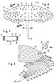
- the brake pad 10 can be provided with the openings 19 shown in broken lines in FIG. 6, one of which is shown in section in FIG. However, it can alternatively or additionally be provided that the brake pad 10 has openings 20 which extend continuously from the front 21 of the brake pad 10 to the rear 22 thereof. These serve to receive and remove friction-preventing soiling, such as water, ice and the like in particular.
- the brake pad 10 can be provided with a dovetail mount 13, as is indicated in FIG. 7. The arrangement of the openings shown was made so that there are sensible passages through the dovetail bracket. However, provision can also be made for the brake lining 10 to be arranged on a carrier plate known per se and not shown in the drawing, in which case the openings 20 then also pass through the carrier plate, not shown.
- the brake pad 10 has an annular configuration, the outer radius Ra and the inner radius Ri, for example start from a common center point M, which corresponds to the center point of the axis of rotation of a brake disk, not shown.
- the proposed arrangement of the individual bores 20 is indicated in FIG. 8, only the centers of the openings 20a of the openings 20 being indicated in FIG.
- the arrangement of the perforations 20 defines itself with regard to circular ring lines K1-K12, the circular ring lines K1-K12 defined by radii R1-R12 starting from the common center point M and increasing uniformly in such a way that at least 30% of each circular line has at least one of the openings provided Tailor or touch, wherein the ratio of the area 23 of the openings of the openings 20 is to be kept in a relation between 2: 100 (minimum) and 35: 100 (maximum) by suitable selection of the diameter D to the entire front surface 24.
- An optimum degree of coverage of the perforations of 100% is to be regarded as the optimum, i.e. that every conceivable circular ring line K1-K12 touches or intersects at least one opening 20, so that every water drop entering any circular ring line is fed to an opening.
- a brake pad 10 provided with corresponding openings 20, which consists of the halves 11 and 12 and is arranged on a dovetail bracket 13 is only shown as an exemplary embodiment in FIG. 9, the arrangement of the openings 20 having been made taking into account an optimal degree of coverage.
- each opening 20 extends from the front 21 to the rear 22 and through the dovetail holder 13, the opening being designed as a through hole with a constant cross section 23.
- the arrangement of the openings 20 is also made in this embodiment in such a way that optimum drainage of the front surface 24 takes place.
- the openings 20 are also arranged in such a way that an optimal contact pressure occurs due to the thermo-elastic deformation of the covering by resetting the corresponding edge.
- FIG. 11 shows a further embodiment of an opening 30 in which the opening 30 is designed as a cone.
- the cone can, as shown in FIG. 11, taper from the front 21 to the rear 22, but it is a design of the cone that it widens from the front 21 to the rear 22, preferred in many cases .
- the opening 31 is designed as a blind hole made from the front side 21 with a constant cross section, the blind hole end 31a merging into a narrower discharge and ventilation channel 32 which emerges on the rear side 22 of the brake lining 10.
- openings are also conceivable, and it is particularly advantageous if a large internal surface area is to be achieved with respect to the opening cross section, if the opening has a star-shaped, elliptical or other suitable cross section.
Landscapes
- Engineering & Computer Science (AREA)
- General Engineering & Computer Science (AREA)
- Mechanical Engineering (AREA)
- Braking Arrangements (AREA)
Claims (6)
- Garniture de frein (10) pour freins à disque à garniture partielle avec un disque de frein dans laquelle des dispositifs d'évacuation de l'eau sont prévus sur le côté avant (21) opposé au côté arrière et qui est prévu pour le contact avec le disque du frein du frein à disque, ce pour quoi la garniture de frein (10) est pourvue d'un certain nombre de découpures (19 ; 20 ; 30 ; 31) qui présentent un écart les unes par rapport aux autres, qui s'étendent de bout en bout du côté avant (21) de la garniture de frein (10) au côté arrière (22) de celle-ci et qui sont appropriées pour recevoir et évacuer des impuretés qui gênent la friction comme l'eau, la glace, l'abrasion ou équivalent,
caractérisée en cea) que la garniture de frein (10) est configurée en une ou plusieurs parties (11, 12) et est à peu près en forme de segment d'anneau de cercle,b) qu'au moins 30 % des lignes d'anneau de cercle quelconques (K1-K12) coupent ou touchent sur le côté avant (21) de la garniture de frein (10) au moins l'une des découpures (20) prévues et qu'il y a au maximum un degré de recouvrement des découpures de 150 % pour lequel chaque ligne d'anneau de cercle concevable (K1-K12) touche ou coupe au moins une découpure (20) si bien que chaque goutte d'eau qui apparaît sur une ligne d'anneau de cercle quelconque est amenée à une découpure (20) ouc) que la surface (23) des ouvertures des découpures (20) sur le côté avant (21) de la garniture de frein (10) se comporte par rapport à l'ensemble de la surface du côté avant (24), y compris la surface (23) des ouvertures des découpures (20), dans un rapport entre 2:100 (minimum) et 35:100 (maximum) oud) que chaque ligne d'anneau de cercle (K1-K12) coupe ou touche sur le côté avant (21) de la garniture de frein (10) au moins une découpure (20) et au maximum cinq découpures (20) par 150 mm de longueur de ligne de cercle. - Garniture de frein selon la revendication 1,
caractérisée en ce
qu'au moins une découpure (19) est configurée de type oblong et en s'étendant dans le sens longitudinal radialement par rapport au centre du cercle (M) de la garniture (10) configurée en forme d'anneau de cercle. - Garniture de frein selon la revendication 1,
caractérisée en ce
que la découpure individuelle (20) est configurée respectivement comme forure de passage avec une section constante pour un diamètre entre 6 mm et 30 mm. - Garniture de frein selon la revendication 1,
caractérisée en ce
que la découpure individuelle (31) est configurée respectivement comme forure à trou borgne ménagé à partir du côté avant (21) avec une section constante pour un diamètre entre 6 mm et 30 mm, l'extrémité de la forure à trou borgne (31a) étant reliée à un canal d'évacuation et d'aération (32) plus étroit que la forure à trou borgne (31) qui sort sur le côté arrière (22) de la garniture de frein (10). - Garniture de frein selon l'une des revendications 1 à 4,
caractérisée en ce
que la découpure individuelle présente respectivement une section étoilée ou elliptique. - Garniture selon l'une des revendications 1, 2 ou 5,
caractérisée en ce
que la découpure individuelle (30) est configurée respectivement avec une section modifiée continuellement du côté avant (21) au côté arrière (22) et qu'elle est en particulier conique.
Applications Claiming Priority (2)
| Application Number | Priority Date | Filing Date | Title |
|---|---|---|---|
| DE9001661U | 1990-02-13 | ||
| DE9001661U DE9001661U1 (de) | 1990-02-13 | 1990-02-13 | Bremsbelag für Teilbelagscheibenbremsen mit einer Bremsscheibe, insbesondere von Schienenfahrzeugen |
Publications (2)
| Publication Number | Publication Date |
|---|---|
| EP0443360A1 EP0443360A1 (fr) | 1991-08-28 |
| EP0443360B1 true EP0443360B1 (fr) | 1994-07-06 |
Family
ID=6850975
Family Applications (1)
| Application Number | Title | Priority Date | Filing Date |
|---|---|---|---|
| EP91101483A Expired - Lifetime EP0443360B1 (fr) | 1990-02-13 | 1991-02-05 | Garniture de frein pour freins à disque à garniture partielle avec disque de frein, spécialement de véhicules ferroviaires |
Country Status (5)
| Country | Link |
|---|---|
| EP (1) | EP0443360B1 (fr) |
| AT (1) | ATE108250T1 (fr) |
| DE (2) | DE9001661U1 (fr) |
| DK (1) | DK0443360T3 (fr) |
| ES (1) | ES2062577T3 (fr) |
Cited By (3)
| Publication number | Priority date | Publication date | Assignee | Title |
|---|---|---|---|---|
| USD362225S (en) | 1994-05-11 | 1995-09-12 | International Brake Industries, Inc. | Disc brake shim |
| DE19849790A1 (de) * | 1998-10-28 | 2000-05-11 | Knorr Bremse Systeme | Abstreifer für ein Reibungselement einer Fahrzeugbremse und damit ausgestatteter Bremsbelag |
| DE102006037802A1 (de) * | 2006-08-12 | 2008-02-14 | Bremskerl-Reibbelagwerke Emmerling Gmbh & Co.Kg. | Ganzbelagträger für Scheibenbremsbeläge in Schienenfahrzeugen |
Families Citing this family (18)
| Publication number | Priority date | Publication date | Assignee | Title |
|---|---|---|---|---|
| DE4006369A1 (de) * | 1990-03-01 | 1991-09-05 | Teves Gmbh Alfred | Bremsklotz mit abgeschraegtem belag |
| DE4140220A1 (de) * | 1991-12-06 | 1993-06-09 | Alfred Teves Gmbh, 6000 Frankfurt, De | Bremsklotz und reibbelag mit ungleichmaessigem reibwert |
| DE19547792A1 (de) * | 1995-12-20 | 1997-06-26 | Bayerische Motoren Werke Ag | Teilbelag-Scheibenbremse |
| EP1600651A1 (fr) * | 2004-05-26 | 2005-11-30 | FEDERAL-MOGUL OPERATIONS ITALY S.r.l. | Plaquette de freins pour freins à disque à garniture partielle |
| US8151433B2 (en) | 2007-08-01 | 2012-04-10 | Federal-Mogul Products, Inc. | Method of making disc brake pads |
| USD588969S1 (en) | 2007-08-01 | 2009-03-24 | Federal-Mogul World Wide, Inc. | Brake friction pad |
| USD588973S1 (en) | 2007-08-01 | 2009-03-24 | Federal Mogul World Wide, Inc. | Brake friction pad |
| USD588968S1 (en) | 2007-08-01 | 2009-03-24 | Federal-Mogul World Wide, Inc. | Brake friction pad |
| USD596092S1 (en) | 2007-08-01 | 2009-07-14 | Federal-Mogul World Wide, Inc. | Brake friction pad |
| US8505698B2 (en) | 2007-08-01 | 2013-08-13 | Federal-Mogul Products, Inc. | Brake pad |
| USD588972S1 (en) | 2007-08-01 | 2009-03-24 | Federal Mogul World Wide, Inc. | Exterior surface configuration of a brake friction pad |
| USD596093S1 (en) | 2007-08-01 | 2009-07-14 | Federal-Mogul World Wide, Inc. | Brake friction pad |
| USD596544S1 (en) | 2007-08-01 | 2009-07-21 | Federal Mogul World Wide, Inc | Brake friction pad |
| USD589419S1 (en) | 2007-08-01 | 2009-03-31 | Federal-Mogul World Wide, Inc. | Brake friction pad |
| USD588970S1 (en) | 2007-08-01 | 2009-03-24 | Federal Mogul World Wide, Inc. | Exterior surface configuration of a brake friction pad |
| USD590310S1 (en) | 2007-08-01 | 2009-04-14 | Federal-Mogul World Wide, Inc. | Brake friction pad |
| USD588971S1 (en) | 2007-08-01 | 2009-03-24 | Federal Mogul World Wide, Inc. | Exterior surface configuration of a brake friction pad |
| USD588974S1 (en) | 2007-08-01 | 2009-03-24 | Federal-Mogul World Wide, Inc. | Exterior surface configuration of a brake friction pad |
Family Cites Families (7)
| Publication number | Priority date | Publication date | Assignee | Title |
|---|---|---|---|---|
| GB360548A (en) * | 1930-09-02 | 1931-11-12 | Morgan Crossley & Co Ltd | Improvements in or relating to friction linings and surfaces |
| FR842684A (fr) * | 1938-02-19 | 1939-06-16 | Ferodo Sa | Fixation de garnitures de friction sur des pièces de tôle |
| DE1430869A1 (de) * | 1964-02-01 | 1969-01-23 | Daimler Benz Ag | Kraftfahrzeug-Scheibenbremse |
| CA1082114A (fr) * | 1978-01-18 | 1980-07-22 | Simon Arbesman | Plaquette de frein a disque et plaque d'appui connexe |
| GB2073834A (en) * | 1980-04-15 | 1981-10-21 | Lear Siegler Inc | Disc Brake Pad and Method of Manufacture |
| US4823921A (en) * | 1988-02-08 | 1989-04-25 | Anstro Manufacturing Co., Inc. | Riveted brake assembly |
| DE8905731U1 (de) * | 1989-05-08 | 1989-07-06 | Becorit-Gesellschaft W. Beckmann Gmbh & Co Kg, 4350 Recklinghausen | Bremsbelag für Teilbelagscheibenbremsen insbesondere an Schienenfahrzeugen |
-
1990
- 1990-02-13 DE DE9001661U patent/DE9001661U1/de not_active Expired - Lifetime
-
1991
- 1991-02-05 EP EP91101483A patent/EP0443360B1/fr not_active Expired - Lifetime
- 1991-02-05 DK DK91101483.5T patent/DK0443360T3/da active
- 1991-02-05 ES ES91101483T patent/ES2062577T3/es not_active Expired - Fee Related
- 1991-02-05 DE DE59102089T patent/DE59102089D1/de not_active Expired - Fee Related
- 1991-02-05 AT AT91101483T patent/ATE108250T1/de not_active IP Right Cessation
Cited By (4)
| Publication number | Priority date | Publication date | Assignee | Title |
|---|---|---|---|---|
| USD362225S (en) | 1994-05-11 | 1995-09-12 | International Brake Industries, Inc. | Disc brake shim |
| DE19849790A1 (de) * | 1998-10-28 | 2000-05-11 | Knorr Bremse Systeme | Abstreifer für ein Reibungselement einer Fahrzeugbremse und damit ausgestatteter Bremsbelag |
| DE19849790C2 (de) * | 1998-10-28 | 2002-11-28 | Knorr Bremse Systeme | Bremsbelag für eine Reibungsbremse eines Fahrzeuges |
| DE102006037802A1 (de) * | 2006-08-12 | 2008-02-14 | Bremskerl-Reibbelagwerke Emmerling Gmbh & Co.Kg. | Ganzbelagträger für Scheibenbremsbeläge in Schienenfahrzeugen |
Also Published As
| Publication number | Publication date |
|---|---|
| EP0443360A1 (fr) | 1991-08-28 |
| DK0443360T3 (da) | 1994-08-01 |
| DE9001661U1 (de) | 1990-06-21 |
| ES2062577T3 (es) | 1994-12-16 |
| DE59102089D1 (de) | 1994-08-11 |
| ATE108250T1 (de) | 1994-07-15 |
Similar Documents
| Publication | Publication Date | Title |
|---|---|---|
| EP0443360A1 (fr) | Garniture de frein pour freins à disque à garniture partielle avec disque de frein, spécialement de véhicules ferroviaires | |
| EP0015993B1 (fr) | Disque pour frein à disque, en particulier pour frein de véhicule | |
| EP3237263B1 (fr) | Garniture de frein à disque à garniture partielle, assemblage d'une garniture de frein avec un porte- garniture, et procédé d'actionnement d'un garniture de frein comprenant un porte-garniture | |
| EP2819799B1 (fr) | Mandrin de frettage avec refroidissement de l'outil | |
| DE60214995T2 (de) | Nasskupplung oder Reibscheibebremse | |
| DE3240579C2 (fr) | ||
| WO2011107081A1 (fr) | Barre de guidage | |
| EP1148963A1 (fr) | Outil d'usinage | |
| DE102014116359B4 (de) | Bremsscheibenrotor | |
| EP1748210A2 (fr) | Frein à disque pour vehicules et couverture protectrice pour un frein à disque | |
| DE2754611C2 (de) | Bremsscheibe für eine Scheibenbremse | |
| DE3432926A1 (de) | Bremsscheibe, insbesondere fuer kraftfahrzeuge | |
| DE19902643C1 (de) | Vorrichtung zum Pressen eines Tampons, insbesondere für die Frauenhygiene | |
| EP1935560A1 (fr) | Meule réfrigérante, système de rectification et outil de rectification | |
| EP2632638A1 (fr) | Lamelle de meulage destinée à être disposée sur une meule entraînée en rotation autour d'un axe de rotation | |
| DE19903276A1 (de) | Spanabhebendes Werkzeug und Verfahren zu seiner Herstellung | |
| DE102009025116A1 (de) | Schleif-und/oder Polierwerkzeug und Herstellverfahren | |
| EP3103575B1 (fr) | Outil d'usinage pour usinage par enlèvement de matière | |
| DE3420653A1 (de) | Schneid- oder abstechwerkzeug | |
| DE19928747A1 (de) | Bremsscheibe für eine Scheibenbremse | |
| DE102016222234A1 (de) | Reibbelaglamelle für eine Lamellenkupplung oder eine Lamellenbremse eines Kraftfahrzeugs | |
| DE2811376C3 (de) | Rotor für Prallmühlen, insbesondere für Sandprallmühlen | |
| AT525457A4 (de) | Bremsbelag | |
| EP1375743B1 (fr) | Rouleau pour machine à papier et procédé pour la fabrication d'un tel rouleau | |
| EP1192023B1 (fr) | Bandes d'usinage de materiau, notamment bandes de poncage et/ou de polissage |
Legal Events
| Date | Code | Title | Description |
|---|---|---|---|
| PUAI | Public reference made under article 153(3) epc to a published international application that has entered the european phase |
Free format text: ORIGINAL CODE: 0009012 |
|
| AK | Designated contracting states |
Kind code of ref document: A1 Designated state(s): AT CH DE DK ES FR IT LI SE |
|
| 17P | Request for examination filed |
Effective date: 19910802 |
|
| 17Q | First examination report despatched |
Effective date: 19921209 |
|
| ITF | It: translation for a ep patent filed | ||
| RAP1 | Party data changed (applicant data changed or rights of an application transferred) |
Owner name: ALLIEDSIGNAL BREMSBELAG GMBH |
|
| GRAA | (expected) grant |
Free format text: ORIGINAL CODE: 0009210 |
|
| AK | Designated contracting states |
Kind code of ref document: B1 Designated state(s): AT CH DE DK ES FR IT LI SE |
|
| REF | Corresponds to: |
Ref document number: 108250 Country of ref document: AT Date of ref document: 19940715 Kind code of ref document: T |
|
| REG | Reference to a national code |
Ref country code: DK Ref legal event code: T3 |
|
| REF | Corresponds to: |
Ref document number: 59102089 Country of ref document: DE Date of ref document: 19940811 |
|
| ET | Fr: translation filed | ||
| REG | Reference to a national code |
Ref country code: ES Ref legal event code: FG2A Ref document number: 2062577 Country of ref document: ES Kind code of ref document: T3 |
|
| EAL | Se: european patent in force in sweden |
Ref document number: 91101483.5 |
|
| PLBE | No opposition filed within time limit |
Free format text: ORIGINAL CODE: 0009261 |
|
| STAA | Information on the status of an ep patent application or granted ep patent |
Free format text: STATUS: NO OPPOSITION FILED WITHIN TIME LIMIT |
|
| 26N | No opposition filed | ||
| PGFP | Annual fee paid to national office [announced via postgrant information from national office to epo] |
Ref country code: FR Payment date: 19971230 Year of fee payment: 8 Ref country code: AT Payment date: 19971230 Year of fee payment: 8 |
|
| PGFP | Annual fee paid to national office [announced via postgrant information from national office to epo] |
Ref country code: CH Payment date: 19980123 Year of fee payment: 8 |
|
| PGFP | Annual fee paid to national office [announced via postgrant information from national office to epo] |
Ref country code: SE Payment date: 19980127 Year of fee payment: 8 |
|
| PGFP | Annual fee paid to national office [announced via postgrant information from national office to epo] |
Ref country code: DK Payment date: 19980213 Year of fee payment: 8 |
|
| PGFP | Annual fee paid to national office [announced via postgrant information from national office to epo] |
Ref country code: DE Payment date: 19980221 Year of fee payment: 8 |
|
| PGFP | Annual fee paid to national office [announced via postgrant information from national office to epo] |
Ref country code: ES Payment date: 19980528 Year of fee payment: 8 |
|
| PG25 | Lapsed in a contracting state [announced via postgrant information from national office to epo] |
Ref country code: AT Free format text: LAPSE BECAUSE OF NON-PAYMENT OF DUE FEES Effective date: 19990205 |
|
| PG25 | Lapsed in a contracting state [announced via postgrant information from national office to epo] |
Ref country code: SE Free format text: LAPSE BECAUSE OF NON-PAYMENT OF DUE FEES Effective date: 19990206 Ref country code: ES Free format text: THE PATENT HAS BEEN ANNULLED BY A DECISION OF A NATIONAL AUTHORITY Effective date: 19990206 |
|
| PG25 | Lapsed in a contracting state [announced via postgrant information from national office to epo] |
Ref country code: LI Free format text: LAPSE BECAUSE OF NON-PAYMENT OF DUE FEES Effective date: 19990228 Ref country code: CH Free format text: LAPSE BECAUSE OF NON-PAYMENT OF DUE FEES Effective date: 19990228 |
|
| PG25 | Lapsed in a contracting state [announced via postgrant information from national office to epo] |
Ref country code: DK Free format text: LAPSE BECAUSE OF NON-PAYMENT OF DUE FEES Effective date: 19990301 |
|
| REG | Reference to a national code |
Ref country code: CH Ref legal event code: PL |
|
| PG25 | Lapsed in a contracting state [announced via postgrant information from national office to epo] |
Ref country code: FR Free format text: LAPSE BECAUSE OF NON-PAYMENT OF DUE FEES Effective date: 19991029 |
|
| EUG | Se: european patent has lapsed |
Ref document number: 91101483.5 |
|
| PG25 | Lapsed in a contracting state [announced via postgrant information from national office to epo] |
Ref country code: DE Free format text: LAPSE BECAUSE OF NON-PAYMENT OF DUE FEES Effective date: 19991201 |
|
| REG | Reference to a national code |
Ref country code: FR Ref legal event code: ST |
|
| REG | Reference to a national code |
Ref country code: DK Ref legal event code: EBP |
|
| REG | Reference to a national code |
Ref country code: ES Ref legal event code: FD2A Effective date: 20010604 |
|
| PG25 | Lapsed in a contracting state [announced via postgrant information from national office to epo] |
Ref country code: IT Free format text: LAPSE BECAUSE OF NON-PAYMENT OF DUE FEES;WARNING: LAPSES OF ITALIAN PATENTS WITH EFFECTIVE DATE BEFORE 2007 MAY HAVE OCCURRED AT ANY TIME BEFORE 2007. THE CORRECT EFFECTIVE DATE MAY BE DIFFERENT FROM THE ONE RECORDED. Effective date: 20050205 |