EP0443371A1 - Method to control space thrusters - Google Patents
Method to control space thrusters Download PDFInfo
- Publication number
- EP0443371A1 EP0443371A1 EP91101653A EP91101653A EP0443371A1 EP 0443371 A1 EP0443371 A1 EP 0443371A1 EP 91101653 A EP91101653 A EP 91101653A EP 91101653 A EP91101653 A EP 91101653A EP 0443371 A1 EP0443371 A1 EP 0443371A1
- Authority
- EP
- European Patent Office
- Prior art keywords
- fuel
- control
- pressure
- engine
- reaction chamber
- Prior art date
- Legal status (The legal status is an assumption and is not a legal conclusion. Google has not performed a legal analysis and makes no representation as to the accuracy of the status listed.)
- Granted
Links
Images


Classifications
-
- B—PERFORMING OPERATIONS; TRANSPORTING
- B64—AIRCRAFT; AVIATION; COSMONAUTICS
- B64G—COSMONAUTICS; VEHICLES OR EQUIPMENT THEREFOR
- B64G1/00—Cosmonautic vehicles
- B64G1/22—Parts of, or equipment specially adapted for fitting in or to, cosmonautic vehicles
- B64G1/40—Arrangements or adaptations of propulsion systems
- B64G1/402—Propellant tanks; Feeding propellants
-
- B—PERFORMING OPERATIONS; TRANSPORTING
- B64—AIRCRAFT; AVIATION; COSMONAUTICS
- B64G—COSMONAUTICS; VEHICLES OR EQUIPMENT THEREFOR
- B64G1/00—Cosmonautic vehicles
- B64G1/22—Parts of, or equipment specially adapted for fitting in or to, cosmonautic vehicles
- B64G1/40—Arrangements or adaptations of propulsion systems
- B64G1/401—Liquid propellant rocket engines
-
- B—PERFORMING OPERATIONS; TRANSPORTING
- B64—AIRCRAFT; AVIATION; COSMONAUTICS
- B64G—COSMONAUTICS; VEHICLES OR EQUIPMENT THEREFOR
- B64G1/00—Cosmonautic vehicles
- B64G1/22—Parts of, or equipment specially adapted for fitting in or to, cosmonautic vehicles
- B64G1/40—Arrangements or adaptations of propulsion systems
- B64G1/411—Electric propulsion
- B64G1/415—Arcjets or resistojets
-
- F—MECHANICAL ENGINEERING; LIGHTING; HEATING; WEAPONS; BLASTING
- F02—COMBUSTION ENGINES; HOT-GAS OR COMBUSTION-PRODUCT ENGINE PLANTS
- F02K—JET-PROPULSION PLANTS
- F02K9/00—Rocket-engine plants, i.e. plants carrying both fuel and oxidant therefor; Control thereof
- F02K9/42—Rocket-engine plants, i.e. plants carrying both fuel and oxidant therefor; Control thereof using liquid or gaseous propellants
- F02K9/44—Feeding propellants
- F02K9/56—Control
-
- F—MECHANICAL ENGINEERING; LIGHTING; HEATING; WEAPONS; BLASTING
- F02—COMBUSTION ENGINES; HOT-GAS OR COMBUSTION-PRODUCT ENGINE PLANTS
- F02K—JET-PROPULSION PLANTS
- F02K9/00—Rocket-engine plants, i.e. plants carrying both fuel and oxidant therefor; Control thereof
- F02K9/42—Rocket-engine plants, i.e. plants carrying both fuel and oxidant therefor; Control thereof using liquid or gaseous propellants
- F02K9/44—Feeding propellants
- F02K9/56—Control
- F02K9/58—Propellant feed valves
-
- B—PERFORMING OPERATIONS; TRANSPORTING
- B64—AIRCRAFT; AVIATION; COSMONAUTICS
- B64G—COSMONAUTICS; VEHICLES OR EQUIPMENT THEREFOR
- B64G1/00—Cosmonautic vehicles
- B64G1/22—Parts of, or equipment specially adapted for fitting in or to, cosmonautic vehicles
- B64G1/24—Guiding or controlling apparatus, e.g. for attitude control
- B64G1/26—Guiding or controlling apparatus, e.g. for attitude control using jets
Definitions
- the invention relates to a method for controlling engines in spacecraft, in which a liquid or gaseous fuel is conveyed from at least one fuel tank into a reaction chamber and propellant gases are generated there by its chemical reaction and / or decomposition and which are operated with continuously decreasing tank pressure. It also relates to a device for performing such a method.
- the object of the invention is to provide a control method for space engines powered by liquid or gaseous fuels, which enables a largely constant thrust size in the range of the best specific momentum of the engine to be maintained over the entire blow-down range. Furthermore, the invention is intended to provide a device for carrying out such a method.
- the invention achieves the first object by a method with the characterizing features of patent claim 1.
- the method according to the invention offers on the one hand the possibility of adapting the thrust generated by different engines, on the other hand it can be used with several engines combined to form a block constant thrust can be easily generated.
- the control method according to the invention overcomes the disadvantages of the blow-down operation described at the outset, in which the pressure in the fuel tank of a hydrazine-powered engine is 22, for example can drop to about 5.5 bar and lead to a decrease in the flow rate to about 25% of the initial amount, is avoided by maintaining the throughput that delivers the optimum pulse value specifically for the engine over the entire pressure range or at least most of it. Due to its integral control behavior, the control device according to the invention is able to compensate for a pressure loss caused by the predetermined throughput. At the same time, when using such a device, the control electronics mentioned at the outset for the heating device of the reaction chamber can either be completely omitted or at least greatly simplified.
- a liquid monopropellant carried in a tank 1, in the present case hydrazine in a reaction or decomposition chamber 2 at higher temperatures that for thrust generation required propellant gases are generated.
- Fuel tank 1 and reaction chamber 2 are only indicated in the drawing, the reaction chamber 2 is also hidden under a panel.
- a control device 3 a valve 4, an injection pipe 6 hidden under a heat shield 5 and leading into the reaction chamber 2, and heating elements 7 to 9, which serve to heat the reaction chamber 2, are provided.
- the outlet nozzle 10 is for the propellant gases generated in the right part of the arrangement shown in Fig. 1.
- control device 3 described in more detail below in FIG. 1 is shown in connection with an engine that is operated with a liquid monopropelant, but it is of course possible in the same way, this device or the control method implemented with this device can also be used in engines that are operated with two-component fuels or with gaseous fuels.
- the control device 3 shown in FIG. 2 consists of a cylindrical chamber 11, the inlet opening 12 of which is connected to the fuel tank 1 and the outlet opening 13 of which is connected to the valve 4.
- An adapter flange 14 arranged on the inlet side has a tubular extension 16 protruding into an inlet space 15, which is open at the end and is provided with a transverse bore 17.
- the transverse bore 17 can also consist of a slot, which can also be present on one side only.
- An adapter flange 18 closing the chamber 11 on the outlet side carries, on a likewise cylindrical extension 19 projecting into the chamber 11, a metallic diaphragm bellows 20, in the interior of which a throttle screw 22 is held on an end plate 21 closing the bellows 20.
- the end plate 21 In the direction of the entry space 15, the end plate 21 has a cylindrical extension 23, the diameter of which is selected so that it fits into the axial bore of the extension 16 of the adapter flange 14.
- the approach 23 is, as shown in Fig. 2, formed as a metering needle by being provided with two axial bores 24 and 25, which are not connected to each other and of which the former with the inlet opening 12 and via a transverse bore 26 with the transverse bore 17 of the adapter flange 14 is connected.
- Another transverse bore 27 connects the inlet space 15 with the axial bore 25, which widens to form an annular space 28 in the vicinity of the throttle screw 22.
- the shape of this annular space 28 is adapted to the outer shape of the throttle screw 22 so that optimal flow conditions result.
- the annular space 28 is finally connected to the outlet opening 13 via a transverse bore 29 introduced into the throttle screw 22 and an axial bore 30.
- the throttle screw 22 is held in the end plate 21 so as to be adjustable in the axial direction, it being possible to adjust it from the outlet opening 13.
- the interior of the bellows 20 is connected via bores 31 to the outlet area 32 of the throttle screw 22.
- a compression spring 33 is arranged inside the bellows 20, which is supported on the one hand on the end plate 21 and on the other hand on an adjusting screw 34, by means of which the spring tension can be changed.
- the adjusting screw 34 is provided with a through hole 35 which connects the outlet area 32 of the throttle screw 22 to an outlet space 36.
- the arrangement described above thus makes it possible to maintain a constant flow rate, in this case approximately 100 mg / sec, over a pressure range between 22 and 5.5 bar in the fuel tank 1. If the lower limit value falls below 5.5 bar in this case, that's how it is with this one For example, throughput considered to be optimal can no longer be achieved and, as in blow-down operation, the throughput assumes a continuously decreasing value.
- control devices shown in FIGS. 3 to 5 are in principle constructed similarly to the one described above, their mode of operation also corresponds to the functional sequence already described.
- the arrangement shown in FIG. 3 differs from that according to FIG. 2 essentially in that in this case the throttle screw 122 is not arranged inside the bellows 120, but in the side wall of the cylindrical chamber housing 111, and in that it is via the metering needle 123 fuel entering the inlet space 115 is conveyed into the outlet space 136 via a channel 132 running in the housing wall. This is connected to the interior of the bellows 120 via bores 131.
- the essential difference between the arrangement according to FIG. 4 and that in FIG. 2 is that the bellows 20 has been replaced by a membrane bellows 220. This measure has the effect that the control device 3 is able to react particularly quickly to pressure changes in the overall system, so that an even more precise maintenance of the predetermined throughput is possible. Due to the different design of the membrane bellows 220 used in this exemplary embodiment, there is at the same time a more compact design of the chamber housing 211, which is shorter than the housing of the chamber 11 in FIG. 2, but at the same time has a larger
- FIG. 6 two different possible uses for one of the control device described above are shown schematically in one image.
- the figure shows a block of engines 402 and 403, respectively, which are used to control the position of a spacecraft. While in the right part of the figure a case is shown in which, according to the above, a control device 404, 405 is assigned to a single engine, in the left part of the figure a control device 406 regulates the flow rate in a fuel line, which at the same time all to this block associated engines 402 supplied.
Landscapes
- Engineering & Computer Science (AREA)
- Chemical & Material Sciences (AREA)
- Combustion & Propulsion (AREA)
- Remote Sensing (AREA)
- Aviation & Aerospace Engineering (AREA)
- Physics & Mathematics (AREA)
- Plasma & Fusion (AREA)
- Mechanical Engineering (AREA)
- General Engineering & Computer Science (AREA)
- Output Control And Ontrol Of Special Type Engine (AREA)
- Physical Or Chemical Processes And Apparatus (AREA)
Abstract
Ein Verfahren dient zur Konstanthaltung des Schubes von Triebwerken in Raumflugkörpern, bei denen aus einem oder mehreren Treibstofftanks (1) ein flüssiger oder gasförmiger Treibstoff bzw. verschiedene Treibstoffkomponenten in eine Reaktionskammer (2) gefördert und aus diesen durch eine chemische Reaktion und/oder Zersetzung Treibgase erzeugt werden und die mit kontinuierlich abnehmendem Tankdruck betrieben werden. Bei diesem Verfahren wird die Differenz zwischen dem Druck im Treibstofftank (1) einseits und dem Druck in der Reaktionskammer (2) andererseits erfaßt und als Stellsignal zur Regelung des Treibstoffdurchflusses verwendet. Eine Vorrichtung zur Durchführung dieses Verfahrens besteht aus einer Anordnung, bei der zwischen dem Treibstofftank (1) und der Reaktionskammer (2) ein Regelorgan (3) vorgesehen ist, das durch eine Veränderung der Druckdifferenz auf der Einlaß- und Auslaßseite ansteuerbar ist.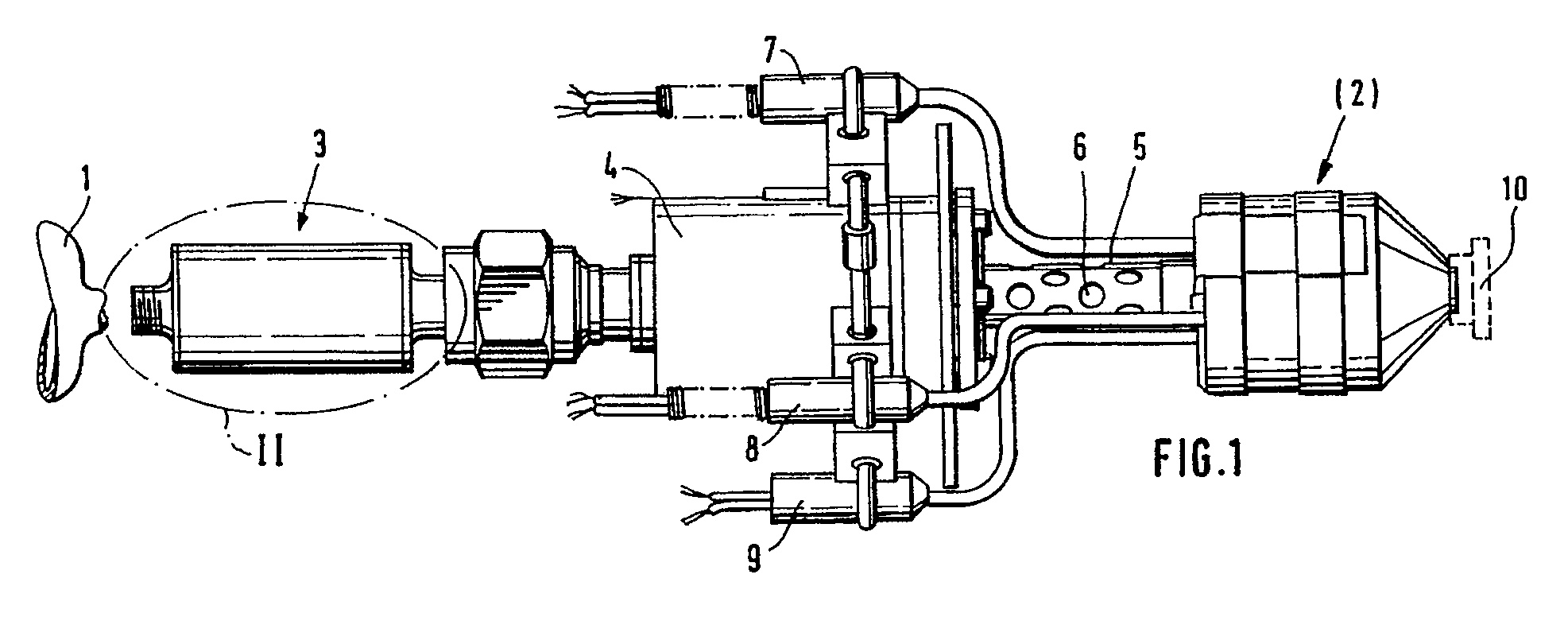
Description
Die Erfindung betrifft ein Verfahren zur Regelung von Triebwerken in Raumflugkörpern, bei denen aus wenigstens einem Treibstofftank ein flüssiger oder gasförmiger Treibstoff in eine Reaktionskammer gefördert wird und dort durch dessen chemische Reaktion und/oder Zersetzung Treibgase erzeugt werden und die mit kontinuierlich abnehmendem Tankdruck betrieben werden. Ferner betrifft sie eine Vorrichtung zur Durchführung eines solchen Verfahrens.The invention relates to a method for controlling engines in spacecraft, in which a liquid or gaseous fuel is conveyed from at least one fuel tank into a reaction chamber and propellant gases are generated there by its chemical reaction and / or decomposition and which are operated with continuously decreasing tank pressure. It also relates to a device for performing such a method.
Bei Triebwerken von Raumflugkörpern, die im sogenannten Blow-down-Betrieb benutzt werden und die überwiegend in Dauerbetrieb laufen, tritt in der Regel eine Abnahme des vom Triebwerk erzeugten spezifischen Impulses und Schubes mit zunehmender Betriebsdauer auf. Die Ursache ist darin zu suchen, daß bei dieser Betriebsweise der Treibstofftank, bzw. im Fall eines Zweikomponenten-Treibstoffs die Treibstofftanks, vor dem Start mit Treibstoff befüllt werden und zum Betrieb des entsprechenden Triebwerks einmalig mit einem Druckgas beaufschlagt werden, durch das der Treibstoff in die Reaktionskammer gefördert wird. Infolge der Treibstoffentnahme sinkt der Druck im Treibstofftank und kehrt nicht wieder auf seinen Anfangswert zurück. Dies aber führt zu einer Abnahme des Treibstoffdurchsatzes im Triebwerk und damit verbunden zu einer Verringerung des Wirkungsgrades des Triebwerks. Dadurch wird für ein solches Triebwerk der eigentlich erreichbare optimale spezifische Impulswert nur für eine, verglichen mit der gesamten Brenndauer, kurze Zeitspanne eingehalten.In the case of engines of spacecraft that are used in so-called blow-down operation and that run predominantly in continuous operation, there is usually a decrease in the specific momentum and generated by the engine Increases with increasing operating time. The reason for this is that in this mode of operation the fuel tank, or in the case of a two-component fuel, the fuel tanks are filled with fuel before starting and are pressurized once with a compressed gas to operate the corresponding engine, through which the fuel in the reaction chamber is promoted. As a result of the fuel withdrawal, the pressure in the fuel tank drops and does not return to its initial value. However, this leads to a decrease in the fuel throughput in the engine and, associated therewith, to a reduction in the efficiency of the engine. As a result, the optimum specific pulse value that can actually be achieved for such an engine is only maintained for a short period of time compared to the total burning time.
Dieser Effekt wirkt sich besonders nachteilig in solchen Fällen aus, in denen eine Reihe nominell gleichartiger Triebwerke beispielsweise zur Lageregelung benutzt werden sollen.This effect is particularly disadvantageous in cases in which a number of nominally similar engines are to be used, for example, for position control.
Zwar ist es bereits bekannt, zur Verminderung dieses nachteiligen Effektes sogenannte Flow-Limiter einzusetzen, d.h. Blenden, durch die die Schübe der einzelnen Triebwerke in einem möglichst engen Toleranzbereich gehalten werden und durch Fertigungstoleranzen bedingte Druck- bzw. Impulsdifferenzen ausgeglichen werden sollen. Die Ergebnisse dieser Maßnahme sind jedoch nicht zufriedenstellend, weil keine Treibstoffregelung erreicht wird, sondern nur Anpassung von Triebwerk zu Triebwerk.It is already known to use so-called flow limiters to reduce this disadvantageous effect, i.e. Apertures through which the thrusts of the individual engines are kept within the narrowest possible tolerance range and pressure and pulse differences caused by manufacturing tolerances are to be compensated. However, the results of this measure are not satisfactory because no fuel control is achieved, but only adaptation from engine to engine.
Darüber hinaus ist es aus der DE-OS 31 28 735 bekannt, bei einem Triebwerk, das auf der Basis der katalytischen Zersetzung eines flüssigen Energieträgers bei erhöhten Temperaturen arbeitet, eine Regelung des erzeugten Schubes in der Weise vorzunehmen, daß die Zersetzungsreaktion und damit die Menge des pro Zeiteinheit erzeugten Treibgases durch eine Veränderung der Temperatur in der Zersetzungskammer gesteuert wird. Dies geschieht über eine elektronische Steuerschaltung, die einen über entsprechende Heizelemente fließenden elektrischen Strom regelt.In addition, it is known from DE-OS 31 28 735, in an engine that is based on the catalytic decomposition of a liquid energy source elevated temperatures works to make a control of the thrust generated in such a way that the decomposition reaction and thus the amount of propellant gas generated per unit time is controlled by a change in the temperature in the decomposition chamber. This is done via an electronic control circuit that regulates an electrical current flowing through appropriate heating elements.
Weiterhin ist es aus der US 44 24 679 bei Hybrid-Triebwerken bekannt wenigstens eine Treibstoffkomponente über eine Vorrichtung mit einer Konstantöffnung mit dazu parallel liegendem Regelventil der Triebwerksbrennkammer zuzuführen. Das Regelventil wird in Abhängigkeit von einem den Druck hinter der Vorrichtung erfassenden Meßgeber geregelt, aber hinreichend konstante Schubimpulse lassen sich damit nicht erzeugen, weil die Druckverhältnisse in dem Treibstofftank unberücksichtigt bleiben.Furthermore, it is known from US Pat. No. 4,424,679 for hybrid engines to supply at least one fuel component to the engine combustion chamber via a device with a constant opening with a control valve in parallel therewith. The control valve is controlled as a function of a measuring sensor which detects the pressure behind the device, but sufficiently constant thrust pulses cannot be generated because the pressure conditions in the fuel tank are not taken into account.
Aufgabe der Erfindung ist es, für durch flüssige oder gasförmige Treibstoffe betriebene Raumfahrttriebwerke ein Regelverfahren anzugeben, das die Einhaltung einer weitgehend gleichbleibenden Schubgröße im Bereich des besten spezifischen Impulses des Triebwerkes über den gesamten Blow-Down-Bereich ermöglicht. Weiterhin soll durch die Erfindung eine Vorrichtung zur Durchführung eines solchen Verfahrens bereitgestellt werden.The object of the invention is to provide a control method for space engines powered by liquid or gaseous fuels, which enables a largely constant thrust size in the range of the best specific momentum of the engine to be maintained over the entire blow-down range. Furthermore, the invention is intended to provide a device for carrying out such a method.
Die Erfindung löst die erste Aufgabe durch ein Verfahren mit den kennzeichnenden Merkmalen des Patentanspruchs 1. Das erfindungsgemäße Verfahren bietet dabei einerseits die Möglichkeit, eine Anpassung des von verschiedenen Triebwerken erzeugten Schubes vorzunehmen, andererseits kann mit seiner Hilfe bei mehreren, zu einem Block zusammengefaßten Triebwerken auf einfache Weise ein gleichbleibender Schub erzeugt werden.The invention achieves the first object by a method with the characterizing features of patent claim 1. The method according to the invention offers on the one hand the possibility of adapting the thrust generated by different engines, on the other hand it can be used with several engines combined to form a block constant thrust can be easily generated.
Zur Lösung der weiteren Aufgabe ist eine Vorrichtung mit den kennzeichnenden Merkmalen des Patentanspruchs 4 vorgesehen.To solve the further problem, a device with the characterizing features of
Durch das erfindungsgemäße Regelverfahren werden die Nachteile des eingangs beschriebenen Blow-Down-Betriebes, bei dem der Druck im Treibstofftank eines hydrazinbetriebenen Triebwerkes beispielsweise von 22 auf etwa 5,5 bar absinken und zu einer Abnahme der Durchflußmenge auf etwa 25 % der Anfangsmenge führen kann, vermieden, indem derjenige Durchsatz, der triebwerkspezifisch den optimalen Impulswert liefert, über den gesamten Druckbereich oder zumindest dessen größten Teil eingehalten wird. Die erfindungsgemäße Regelungsvorrichtung ist dabei aufgrund ihres integralen Regelungsverhaltens in der Lage, einen durch den vorgegebenen Durchsatz hervorgerufenen Druckverlust wieder auszugleichen. Zugleich kann bei einer Verwendung einer solchen Vorrichtung die eingangs erwähnte Ansteuerelektronik für die Aufheizeinrichtung der Reaktionskammer entweder ganz entfallen oder zumindest stark vereinfacht werden.The control method according to the invention overcomes the disadvantages of the blow-down operation described at the outset, in which the pressure in the fuel tank of a hydrazine-powered engine is 22, for example can drop to about 5.5 bar and lead to a decrease in the flow rate to about 25% of the initial amount, is avoided by maintaining the throughput that delivers the optimum pulse value specifically for the engine over the entire pressure range or at least most of it. Due to its integral control behavior, the control device according to the invention is able to compensate for a pressure loss caused by the predetermined throughput. At the same time, when using such a device, the control electronics mentioned at the outset for the heating device of the reaction chamber can either be completely omitted or at least greatly simplified.
Im folgenden soll die Erfindung anhand von in der Zeichnung dargestellten Ausführungsbeispielen näher erläutert werden. Es zeigen:
- Fig. 1
- ein Triebwerk für Raumfahrzeuge mit einer Regelungsvorrichtung gemäß der Erfindung,
- Fig. 2
- eine vergrößerte Darstellung des in Fig. 1 gekennzeichneten Bereichs II,
- Fig. 3
- eine zweite Ausführungsform der in Fig. 2 dargestellten Anordnung,
- Fig. 4
- eine dritte Ausführungsform der in Fig. 3 dargestellten Anordnung,
- Fig. 5
- eine vierte Ausführungsform der in Fig. 4 dargestellten Anordnung und
- Fig. 6
- eine schematische Darstellung Darstellung einer Triebwerkskonfiguration bei einem Raumfahrzeug.
- Fig. 1
- an engine for spacecraft with a control device according to the invention,
- Fig. 2
- 2 shows an enlarged view of area II marked in FIG. 1,
- Fig. 3
- 2 shows a second embodiment of the arrangement shown in FIG. 2,
- Fig. 4
- 3 shows a third embodiment of the arrangement shown in FIG. 3,
- Fig. 5
- a fourth embodiment of the arrangement shown in Fig. 4 and
- Fig. 6
- a schematic representation of an engine configuration in a spacecraft.
In den Figuren sind gleich Bauteile mit den gleichen Bezugszeichen versehen.In the figures, the same components are provided with the same reference symbols.
Bei dem in Fig. 1 dargestellten Raumfahrttriebwerk handelt es sich um ein Triebwerk, bei dem durch die katalytische Zersetzung eines in einem Tank 1 mitgeführten flüssigen Monopropellants, im vorliegenden Fall Hydrazin, in einer Reaktions- bzw. Zersetzungskammer 2 bei höheren Temperaturen die für die Schuberzeugung erforderlichen Treibgase erzeugt werden. Treibstofftank 1 und Reaktionskammer 2 sind dabei in der Zeichnung nur andeutungsweise dargestellt, wobei die Reaktionskammer 2 überdies unter einer Verkleidung verborgen ist. Zwischen diesen beiden Komponenten sind eine Regelungsvorrichtung 3, ein Ventil 4, ein unter einem Hitzeschild 5 verborgenes, in die Reaktionskammer 2 führendes Einspritzrohr 6 sowie Heizelemente 7, bis 9, die zur Aufheizung der Reaktionskammer 2 dienen vorgesehend Die Austrittsdüse 10 für die erzeugten Treibgase befindet sich im rechten Teil der in Fig. 1 dargestellten Anordnung.1 is an engine in which, through the catalytic decomposition of a liquid monopropellant carried in a tank 1, in the present case hydrazine, in a reaction or
Angemerkt sei, daß die nachfolgend näher beschriebene Regelungsvorrichtung 3 in Fig. 1 zwar im Zusammenhang mit einem Triebwerk dargestellt ist, das mit einem flüssigen Monopropelant betrieben wird, es aber selbstverständlich in gleicher Weise möglich ist, diese Vorrichtung bzw. das mit dieser Vorrichtung realisierte Regelungsverfahren auch bei Triebwerken einzusetzen, die mit Zweikomponenten-Treibstoffen bzw. mit gasförmigen Treibstoffen betrieben werden.It should be noted that the
Die in Fig. 2 dargestellte Regelungsvorrichtung 3 besteht aus einer zylindrischen Kammer 11, deren Einlaßöffnung 12 mit dem Treibstofftank 1 und deren Auslaßöffnung 13 mit dem Ventil 4 verbunden ist. Ein auf der Einlaßseite angeordneter Adapterflansch 14 weist einen in einen Eintrittsraum 15 ragenden rohrförmigen Ansatz 16 auf, der endseitig offen ausgebildet ist und der mit einer Querbohrung 17 versehen ist. Die Querbohrung 17 kann außerdem aus einem Schlitz bestehen, welcher auch nur einseitig vorhanden sein kann.The
Ein die Kammer 11 auslaßseitig verschließender Adapterflansch 18 trägt auf einem ebenfalls zylindrischen, in die Kammer 11 ragenden Ansatz 19 einen metallischen Membranbalg 20, in dessen Inneren auf einer den Balg 20 verschließenden Endplatte 21 eine Drosselschraube 22 gehaltert ist. In Richtung auf den Eintrittsraum 15 hin weist die Endplatte 21 einen zylindrischen Ansatz 23 auf, dessen Durchmesser so gewählt ist, daß er in die axiale Bohrung des Ansatzes 16 des Adapterflansches 14 paßt.An
Der Ansatz 23 ist, wie aus Fig. 2 ersichtlich, als Dosiernadel ausgebildet, indem er mit zwei axialen Bohrungen 24 und 25 versehen ist, die untereinander nicht verbunden sind und von denen die erstere mit der Einlaßöffnung 12 und über eine Querbohrung 26 mit der Querbohrung 17 des Adapterflansches 14 in Verbindung steht. Eine weitere Querbohrung 27 verbindet den Eintrittsraum 15 mit der axialen Bohrung 25, die sich in der Umgebung der Drosselschraube 22 zu einem Ringraum 28 erweitert. Die Form dieses Ringraumes 28 ist dabei der äußeren Form der Drosselschraube 22 so angepaßt, daß sich optimale Strömungsbedingungen ergeben.The approach 23 is, as shown in Fig. 2, formed as a metering needle by being provided with two
Über eine in die Drosselschraube 22 eingebrachte Querbohrung 29 sowie eine axiale Bohrung 30 ist der Ringraum 28 schließlich mit der Auslaßöffnung 13 verbunden. Die Drosselschraube 22 ist dabei in der Endplatte 21 in axialer Richtung verstellbar gehaltert, wobei eine Verstellung von der Auslaßöffnung 13 her erfolgen kann.The
Der Innenraum des Balges 20 steht über Bohrungen 31 mit dem Austrittsbereich 32 der Drosselschraube 22 in Verbindung. Im Inneren des Balges 20 ist überdies eine Druckfeder 33 angeordnet, die sich einerseits an der Endplatte 21 und andererseits an einer Justierschraube 34 abstützt, mit deren Hilfe die Federspannung veränderbar ist. Die Justierschraube 34 ist mit einer Durchgangsbohrung 35 versehen, die den Austrittsbereich 32 der Drosselschraube 22 mit einem Auslaßraum 36 verbindet.The interior of the
Die Wirkungsweise der vorstehend beschriebenen Anordnung ist wie folgt:
Bei zunächst geschlossenem Ventil 4 nimmt der Balg 20 die in Fig. 2 dargestellte Position ein, und es herrscht im Eintrittsraum 15, im Auslaßraum 36 sowie im Inneren des Balges 20 der gleich Druck. Nach dem Öffnen des Ventils 4, das auch als Flow Control Valve bezeichnet wird, verringert sich im Auslaßraum 36 sowie im Inneren des Balges 20 der Druck und bewirkt auf diese Weise eine Kontraktion des Balges 20. Dies wiederum führt zu einer Verschiebung der Dosiernadel 23 gegenüber dem Ansatz 16, was zur Folge hat, daß die Bohrungen 17 und 26 nicht mehr deckungsgleich sind, so daß der durchströmbare Querschnitt verringert wird, wodurch ein zusätzlicher Druckabfall zwischen dem Eintrittsraum 15 und dem Auslaßraum 36 entsteht. Der Weg des Balges 20 ist dabei durch einen Anschlag 37 begrenzt.The operation of the arrangement described above is as follows:
When the
Insgesamt ergibt sich an der Drosselschraube 22 ein charakteristischer Druckverlust, der von der eingestellten Durchsatzmenge abhängt. Ein typischer Wert bei einem eingestellten Durchsatz von 110 mg pro Sekunde liegt bei etwa 2 bar. Ein weiterer Druckverlust tritt im Einspritzrohr des Ventils auf, dieser liegt typischerweise bei etwa 1,5 bar. Geht man von einer Anfangssituation aus, bei der die Druckdifferenz zwischen dem Treibstofftank 1 und der Reaktionskammer 2 beispielsweise 20 bar beträgt, so wird sich aufgrund der wirkenden hydraulischen Kräfte der Balg 20 so weit kontrahieren, bis die durchströmbare Querschnittsfläche zwischen der Dosiernadel und der Querbohrung 17 am Ansatz 16 des Einlaß-Adapterflansches 14 sich auf einen Wert eingestellt hat, bei dem an dieser Stelle ein Druckverlust von etwa 16,5 bar (= 20 - 2 - 1,5 bar) ergibt, d.h. der Balg 20 wird nur einen sehr geringen durchströmbaren Querschnitt freigeben. Nimmt mit zunehmender Betriebsdauer des Triebwerks der Druck im Treibstofftank 1 ab, so entspannt sich die Druckfeder 33 und mit ihr der Balg 20 immer mehr, bis schließlich bei einer Druckdifferenz von nur noch 3,5 bar die volle Querschnittsfläche zur Verfügung steht. Geht man davon aus, daß in der Reaktionskammer ein Druck von etwa 2 bar herrscht, so ist dies bei einem Druck von etwa 5,5 bar im Treibstofftank 1 der Fall.Overall, there is a characteristic pressure loss at the
Insgesamt ermöglicht die vorstehend beschriebene Anordnung somit die Aufrechterhaltung einer konstanten Durchflußmenge, in diesem Fall etwa 100 mg/sec, über einen Druckbereich zwischen 22 und 5,5 bar im Treibstofftank 1. Wird der untere Grenzwert von in diesem Fall 5,5 bar unterschritten, so ist der bei diesem Beispiel als optimal angesehene Durchsatz nicht mehr erreichbar und der Durchsatz nimmt, wie im Blow-down-Betrieb, einen kontinuierlich geringer werdenden Wert an.Overall, the arrangement described above thus makes it possible to maintain a constant flow rate, in this case approximately 100 mg / sec, over a pressure range between 22 and 5.5 bar in the fuel tank 1. If the lower limit value falls below 5.5 bar in this case, that's how it is with this one For example, throughput considered to be optimal can no longer be achieved and, as in blow-down operation, the throughput assumes a continuously decreasing value.
Die in den Figuren 3 bis 5 dargestellten Regelungsvorrichtungen sind im Prinzip ähnlich aufgebaut wie die vorangehend beschriebene, ihre Funktionsweise entspricht ebenfalls dem bereits geschilderten Funktionsablauf.The control devices shown in FIGS. 3 to 5 are in principle constructed similarly to the one described above, their mode of operation also corresponds to the functional sequence already described.
So unterscheidet sich die in Fig. 3 dargestellte Anordnung von der gemäß Fig. 2 im wesentlichen darin, daß in diesem Fall die Drosselschraube 122 nicht im Inneren des Balges 120, sondern in der Seitenwand des zylindrischen Kammergehäuses 111 angeordnet ist und daß der über die Dosiernadel 123 in den Eintrittsraum 115 gelangende Treibstoff über einen in der Gehäusewand verlaufenden Kanal 132 in den Auslaßraum 136 gefördert wird. Dieser steht über Bohrungen 131 mit dem Innenraum des Balges 120 in Verbindung. Der wesentliche Unterschied zwischen der Anordnung gemäß Fig. 4 und derjenigen in Fig. 2 besteht darin, daß der Wellenbalg 20 durch einen Membranbalg 220 ersetzt wurde. Diese Maßnahme bewirkt, daß die Regelvorrichtung 3 besonders rasch auf Druckveränderungen im Gesamtsystem zu reagieren vermag, so daß eine noch exaktere Einhaltung des vorgegebenen Durchsatzes möglich ist. Bedingt durch die unterschiedliche Bauform des bei diesem Ausführungsbeispiel verwendeten Membranbalges 220 ergibt sich hier zugleich eine kompaktere Bauweise des Kammergehäuses 211, das kürzer als das Gehäuse der Kammer 11 in Fig. 2 ist, zugleich aber einen größeren Durchmesser aufweist.The arrangement shown in FIG. 3 differs from that according to FIG. 2 essentially in that in this case the
Bei der in Fig. 5 dargestellten Anordnung schließlich ist der Membranbalg 20 gemäß Fig. 2 durch eine Rillenmembranscheibe 320 ersetzt worden, die an einem ringförmigen inneren Ansatz 338 des Kammergehäuses 311 gehaltert ist. Der Vorteil dieser Anordnung ist darin zu sehen, daß aufgrund der geringeren Masse der Membranscheibe 320 im Vergleich zum einem Membran- oder Faltenbalg sich nicht nur insgesamt eine Gewichtseinsparung ergibt, sondern daß diese Anordnung zugleich ein besonders sensibles Regelverhalten aufweist.Finally, in the arrangement shown in FIG. 5, the diaphragm bellows 20 according to FIG
Bei der Darstellung in Fig. 6 sind schematisch in einem Bild zwei verschiedene Einsatzmöglichkeiten für eine der vorstehend beschriebenen Regelvorrichtung dargestellt. Die Figur zeigt neben einem Haupttriebwerk 401 jeweils einen Block von Triebwerken 402 bzw. 403, die der Lageregelung eines Raumflugkörpers dienen. Während im rechten Teil der Figur ein Fall dargestellt ist, bei dem, entsprechend dem vorstehend geschilderten, jeweils eine Reglungsvorrichtung 404,405 einem einzelnen Triebwerk zugeordnet ist, regelt im linken Teil der Figur eine Regelungsvorrichtung 406 die Durchflußmenge in einer Treibstoffleitung, die gleichzeitig sämtliche zu diesem Block gehörigen Triebwerke 402 versorgt.In the illustration in FIG. 6, two different possible uses for one of the control device described above are shown schematically in one image. In addition to a
Abschließend sei angemerkt, daß sich die vorstehend beschriebenen Ausführungsbeispiele zwar ausschließlich auf die Verwendung eines Einkomponenten-Treibstoffes beziehen, daß aber, wie bereits erwähnt, die Anwendung des beschriebenen Regelungsverfahrens auch auf Zweikomponenten-Treibstoffe möglich ist, indem zwei Regelungsvorrichtungen vorgesehen werden, die den Durchsatz in jedem der beiden Zuführsysteme für die Treibstoffkomponenten für sich genommen konstant halten.Finally, it should be noted that the exemplary embodiments described above relate exclusively to the use of a one-component fuel, but that, as already mentioned, the application of the described control method to two-component fuels is also possible by providing two control devices which increase the throughput keep constant in each of the two supply systems for the fuel components.
Claims (15)
Applications Claiming Priority (2)
| Application Number | Priority Date | Filing Date | Title |
|---|---|---|---|
| DE4005607A DE4005607C1 (en) | 1990-02-22 | 1990-02-22 | |
| DE4005607 | 1990-02-22 |
Publications (2)
| Publication Number | Publication Date |
|---|---|
| EP0443371A1 true EP0443371A1 (en) | 1991-08-28 |
| EP0443371B1 EP0443371B1 (en) | 1994-09-21 |
Family
ID=6400745
Family Applications (1)
| Application Number | Title | Priority Date | Filing Date |
|---|---|---|---|
| EP91101653A Expired - Lifetime EP0443371B1 (en) | 1990-02-22 | 1991-02-07 | Method to control space thrusters |
Country Status (2)
| Country | Link |
|---|---|
| EP (1) | EP0443371B1 (en) |
| DE (1) | DE4005607C1 (en) |
Cited By (2)
| Publication number | Priority date | Publication date | Assignee | Title |
|---|---|---|---|---|
| EP0791742A1 (en) * | 1996-02-23 | 1997-08-27 | Trw Inc. | Low power arcjet propellant feed system |
| RU2399562C2 (en) * | 2008-07-14 | 2010-09-20 | Открытое акционерное общество "Ракетно-космическая корпорация "Энергия" имени С.П. Королева" | Rocket boost unit engine plant |
Families Citing this family (7)
| Publication number | Priority date | Publication date | Assignee | Title |
|---|---|---|---|---|
| RU2133866C1 (en) * | 1991-03-29 | 1999-07-27 | Федеральное государственное унитарное предприятие Конструкторское бюро химавтоматики | Device for control over liquid-propellant rocket engine performance |
| RU2180704C2 (en) * | 2000-03-06 | 2002-03-20 | Федеральное государственное унитарное предприятие "НПО ТЕХНОМАШ" | Method of control of mode of operation of liquid-propellant rocket engine plant |
| RU2180705C2 (en) * | 2000-03-10 | 2002-03-20 | Федеральное государственное унитарное предприятие "НПО ТЕХНОМАШ" | Method of control of mode of operation of liquid-propellant rocket engine plant |
| RU2418188C1 (en) * | 2010-03-17 | 2011-05-10 | Федеральное Государственное Унитарное Предприятие "Научно-Производственное Объединение "Техномаш" | Method of controlling rocket fluid-propellant engine operation |
| RU2486362C1 (en) * | 2011-10-28 | 2013-06-27 | Федеральное государственное унитарное предприятие "Государственный космический научно-производственный центр имени М.В. Хруничева" | Method and device for control over primary parameters of liquid-propellant rocket engines |
| RU2499906C1 (en) * | 2012-05-25 | 2013-11-27 | Федеральное Государственное Унитарное Предприятие "Научно-Производственное Объединение "Техномаш" | Method to regulate mode of operation of liquid rocket propulsion system |
| RU2622677C1 (en) * | 2016-07-05 | 2017-06-19 | Акционерное общество "Конструкторское бюро химавтоматики" | Rps fuel component management system |
Citations (8)
| Publication number | Priority date | Publication date | Assignee | Title |
|---|---|---|---|---|
| US2794318A (en) * | 1952-08-22 | 1957-06-04 | Aerojet General Co | Propellant supply system for jet propulsion motor |
| US2986883A (en) * | 1955-12-19 | 1961-06-06 | Li Yao Tzu | Combustion stabilizer |
| US2995008A (en) * | 1953-02-26 | 1961-08-08 | Phillips Petroleum Co | Fuel and oxidant control system and process for variable thrust rocket and jet engines |
| DE1301932B (en) * | 1963-02-25 | 1969-08-28 | Trw Inc | Device for controlling the thrust of rocket engines |
| DE1751389A1 (en) * | 1968-05-22 | 1971-07-08 | Gerd Zelck | Propellant feed device for a rocket engine operating with at least one liquid fuel |
| US3724213A (en) * | 1970-12-04 | 1973-04-03 | Messerschmitt Boelkow Blohm | Fuel system, in particular for rocket engines |
| WO1987002098A1 (en) * | 1985-10-01 | 1987-04-09 | Hughes Aircraft Company | A method for controlling the utilization of fluid bipropellant in a spacecraft rocket engine |
| EP0275361A2 (en) * | 1987-01-20 | 1988-07-27 | Rockwell International Corporation | Mass flow rate regulator |
Family Cites Families (2)
| Publication number | Priority date | Publication date | Assignee | Title |
|---|---|---|---|---|
| DE3128735A1 (en) * | 1981-07-21 | 1983-02-10 | Erno-Raumfahrttechnik Gmbh, 2800 Bremen | ENGINE, ESPECIALLY FOR SPACING BODIES |
| US4424679A (en) * | 1981-09-10 | 1984-01-10 | The United States Of America As Represented By The Secretary Of The Air Force | Constant thrust hybrid rocket motor |
-
1990
- 1990-02-22 DE DE4005607A patent/DE4005607C1/de not_active Expired - Lifetime
-
1991
- 1991-02-07 EP EP91101653A patent/EP0443371B1/en not_active Expired - Lifetime
Patent Citations (8)
| Publication number | Priority date | Publication date | Assignee | Title |
|---|---|---|---|---|
| US2794318A (en) * | 1952-08-22 | 1957-06-04 | Aerojet General Co | Propellant supply system for jet propulsion motor |
| US2995008A (en) * | 1953-02-26 | 1961-08-08 | Phillips Petroleum Co | Fuel and oxidant control system and process for variable thrust rocket and jet engines |
| US2986883A (en) * | 1955-12-19 | 1961-06-06 | Li Yao Tzu | Combustion stabilizer |
| DE1301932B (en) * | 1963-02-25 | 1969-08-28 | Trw Inc | Device for controlling the thrust of rocket engines |
| DE1751389A1 (en) * | 1968-05-22 | 1971-07-08 | Gerd Zelck | Propellant feed device for a rocket engine operating with at least one liquid fuel |
| US3724213A (en) * | 1970-12-04 | 1973-04-03 | Messerschmitt Boelkow Blohm | Fuel system, in particular for rocket engines |
| WO1987002098A1 (en) * | 1985-10-01 | 1987-04-09 | Hughes Aircraft Company | A method for controlling the utilization of fluid bipropellant in a spacecraft rocket engine |
| EP0275361A2 (en) * | 1987-01-20 | 1988-07-27 | Rockwell International Corporation | Mass flow rate regulator |
Cited By (2)
| Publication number | Priority date | Publication date | Assignee | Title |
|---|---|---|---|---|
| EP0791742A1 (en) * | 1996-02-23 | 1997-08-27 | Trw Inc. | Low power arcjet propellant feed system |
| RU2399562C2 (en) * | 2008-07-14 | 2010-09-20 | Открытое акционерное общество "Ракетно-космическая корпорация "Энергия" имени С.П. Королева" | Rocket boost unit engine plant |
Also Published As
| Publication number | Publication date |
|---|---|
| DE4005607C1 (en) | 1991-07-25 |
| EP0443371B1 (en) | 1994-09-21 |
Similar Documents
| Publication | Publication Date | Title |
|---|---|---|
| EP0970304B1 (en) | Device and method for controlling pressure in storage injection systems with an electromagnetically actuated pressure control member | |
| EP2238338B1 (en) | Fuel injection system for an internal combustion engine | |
| DE69624964T2 (en) | Device for controlling the high-pressure fuel supply to a high-pressure fuel reservoir, for example for motor vehicles | |
| EP0686763A1 (en) | Fuel injection valve for internal combustion engines | |
| DE19515204A1 (en) | Fuel system | |
| DE102008027516B3 (en) | Method for injection quantity deviation detection and correction of an injection quantity and injection system | |
| DE3631287C2 (en) | Ram jet engine and missile equipped with such a ram jet engine | |
| EP0657644A2 (en) | Fuel injection device for internal combustion engines | |
| DE602004010490T2 (en) | Gas supply system for an internal combustion engine with a controlled by a control pressure pressure reducing valve | |
| EP0443371B1 (en) | Method to control space thrusters | |
| DE602004003796T2 (en) | Gas supply system for an internal combustion engine with improved pressure regulator | |
| DE2710262A1 (en) | FUEL CONVEYOR | |
| DE2423002A1 (en) | CONVEYOR LINE FOR PRESSURIZED, PREFERABLY GAS MEDIA, WITH A PRESSURE REGULATOR AND AT LEAST ONE SHUT-OFF VALVE | |
| DE2642219C3 (en) | Device for supplying internal combustion engines with fuel | |
| EP0731315A1 (en) | Nozzle shut-off valve and pressure spray nozzle with such a shut-off valve | |
| DE10022275A1 (en) | Overpressure valve for fuel supply system has valve seat guide part that accepts valve ball and is of width up to 60 microns larger than ball diameter so ball can slide within guide part | |
| DE2319762C3 (en) | Differential pressure control valve for a fuel supply system | |
| EP2807367B1 (en) | Device for injecting fuel into the combustion chamber of an internal combustion engine | |
| DE3039613C2 (en) | System for regulating the idling speed of gasoline engines | |
| EP1172545A1 (en) | Ignition system for combustion chambers in rocket engines | |
| DE2431674C2 (en) | Mixing valve for incinerators and the like. | |
| DE3200802A1 (en) | "REMOTE-CONTROLLED INJECTION DEVICE ON A MIXING HEAD" | |
| DE2756513A1 (en) | ENGINE FUEL REGULATOR | |
| DE102023005409B4 (en) | Control device for controlling a pressure of a fluid | |
| DE3132994A1 (en) | Method and appliance for mixing liquids |
Legal Events
| Date | Code | Title | Description |
|---|---|---|---|
| PUAI | Public reference made under article 153(3) epc to a published international application that has entered the european phase |
Free format text: ORIGINAL CODE: 0009012 |
|
| AK | Designated contracting states |
Kind code of ref document: A1 Designated state(s): FR GB IT NL |
|
| 17P | Request for examination filed |
Effective date: 19910926 |
|
| 17Q | First examination report despatched |
Effective date: 19930521 |
|
| GRAA | (expected) grant |
Free format text: ORIGINAL CODE: 0009210 |
|
| AK | Designated contracting states |
Kind code of ref document: B1 Designated state(s): FR GB IT NL |
|
| GBT | Gb: translation of ep patent filed (gb section 77(6)(a)/1977) |
Effective date: 19941018 |
|
| ET | Fr: translation filed | ||
| ITF | It: translation for a ep patent filed | ||
| RAP2 | Party data changed (patent owner data changed or rights of a patent transferred) |
Owner name: DAIMLER-BENZ AEROSPACE AKTIENGESELLSCHAFT |
|
| NLT2 | Nl: modifications (of names), taken from the european patent patent bulletin |
Owner name: DAIMLER-BENZ AEROSPACE AKTIENGESELLSCHAFT TE MUENC |
|
| PLBE | No opposition filed within time limit |
Free format text: ORIGINAL CODE: 0009261 |
|
| STAA | Information on the status of an ep patent application or granted ep patent |
Free format text: STATUS: NO OPPOSITION FILED WITHIN TIME LIMIT |
|
| 26N | No opposition filed | ||
| REG | Reference to a national code |
Ref country code: GB Ref legal event code: IF02 |
|
| PGFP | Annual fee paid to national office [announced via postgrant information from national office to epo] |
Ref country code: GB Payment date: 20020103 Year of fee payment: 12 |
|
| PGFP | Annual fee paid to national office [announced via postgrant information from national office to epo] |
Ref country code: FR Payment date: 20020227 Year of fee payment: 12 |
|
| PGFP | Annual fee paid to national office [announced via postgrant information from national office to epo] |
Ref country code: NL Payment date: 20020228 Year of fee payment: 12 |
|
| PG25 | Lapsed in a contracting state [announced via postgrant information from national office to epo] |
Ref country code: GB Free format text: LAPSE BECAUSE OF NON-PAYMENT OF DUE FEES Effective date: 20030207 |
|
| PG25 | Lapsed in a contracting state [announced via postgrant information from national office to epo] |
Ref country code: NL Free format text: LAPSE BECAUSE OF NON-PAYMENT OF DUE FEES Effective date: 20030901 |
|
| GBPC | Gb: european patent ceased through non-payment of renewal fee | ||
| PG25 | Lapsed in a contracting state [announced via postgrant information from national office to epo] |
Ref country code: FR Free format text: LAPSE BECAUSE OF NON-PAYMENT OF DUE FEES Effective date: 20031031 |
|
| NLV4 | Nl: lapsed or anulled due to non-payment of the annual fee |
Effective date: 20030901 |
|
| REG | Reference to a national code |
Ref country code: FR Ref legal event code: ST |
|
| PG25 | Lapsed in a contracting state [announced via postgrant information from national office to epo] |
Ref country code: IT Free format text: LAPSE BECAUSE OF NON-PAYMENT OF DUE FEES;WARNING: LAPSES OF ITALIAN PATENTS WITH EFFECTIVE DATE BEFORE 2007 MAY HAVE OCCURRED AT ANY TIME BEFORE 2007. THE CORRECT EFFECTIVE DATE MAY BE DIFFERENT FROM THE ONE RECORDED. Effective date: 20050207 |