EP0443463A1 - Kamera - Google Patents
Kamera Download PDFInfo
- Publication number
- EP0443463A1 EP0443463A1 EP91102203A EP91102203A EP0443463A1 EP 0443463 A1 EP0443463 A1 EP 0443463A1 EP 91102203 A EP91102203 A EP 91102203A EP 91102203 A EP91102203 A EP 91102203A EP 0443463 A1 EP0443463 A1 EP 0443463A1
- Authority
- EP
- European Patent Office
- Prior art keywords
- optical accessory
- interchangeable lens
- contact
- camera system
- information
- Prior art date
- Legal status (The legal status is an assumption and is not a legal conclusion. Google has not performed a legal analysis and makes no representation as to the accuracy of the status listed.)
- Granted
Links
Images

Classifications
-
- G—PHYSICS
- G03—PHOTOGRAPHY; CINEMATOGRAPHY; ANALOGOUS TECHNIQUES USING WAVES OTHER THAN OPTICAL WAVES; ELECTROGRAPHY; HOLOGRAPHY
- G03B—APPARATUS OR ARRANGEMENTS FOR TAKING PHOTOGRAPHS OR FOR PROJECTING OR VIEWING THEM; APPARATUS OR ARRANGEMENTS EMPLOYING ANALOGOUS TECHNIQUES USING WAVES OTHER THAN OPTICAL WAVES; ACCESSORIES THEREFOR
- G03B17/00—Details of cameras or camera bodies; Accessories therefor
- G03B17/02—Bodies
- G03B17/12—Bodies with means for supporting objectives, supplementary lenses, filters, masks, or turrets
-
- G—PHYSICS
- G03—PHOTOGRAPHY; CINEMATOGRAPHY; ANALOGOUS TECHNIQUES USING WAVES OTHER THAN OPTICAL WAVES; ELECTROGRAPHY; HOLOGRAPHY
- G03B—APPARATUS OR ARRANGEMENTS FOR TAKING PHOTOGRAPHS OR FOR PROJECTING OR VIEWING THEM; APPARATUS OR ARRANGEMENTS EMPLOYING ANALOGOUS TECHNIQUES USING WAVES OTHER THAN OPTICAL WAVES; ACCESSORIES THEREFOR
- G03B17/00—Details of cameras or camera bodies; Accessories therefor
- G03B17/02—Bodies
- G03B17/12—Bodies with means for supporting objectives, supplementary lenses, filters, masks, or turrets
- G03B17/14—Bodies with means for supporting objectives, supplementary lenses, filters, masks, or turrets interchangeably
-
- H—ELECTRICITY
- H04—ELECTRIC COMMUNICATION TECHNIQUE
- H04N—PICTORIAL COMMUNICATION, e.g. TELEVISION
- H04N23/00—Cameras or camera modules comprising electronic image sensors; Control thereof
- H04N23/60—Control of cameras or camera modules
- H04N23/66—Remote control of cameras or camera parts, e.g. by remote control devices
- H04N23/663—Remote control of cameras or camera parts, e.g. by remote control devices for controlling interchangeable camera parts based on electronic image sensor signals
Definitions
- This invention relates to a camera arranged to permit an optical accessory to be mounted thereon.
- a camera system taking into consideration the use of such accessories as a telephoto conversion lens (hereinafter referred to as a tele-converter), etc.
- a tele-converter which increases the focal length of a photo-taking lens by two or 1.4 times is in great demand.
- a camera system therefore, must be designed to permit data correction in anticipation of an extender to be mounted for that purpose. More specifically, in the case of a camera system of the kind performing automatic focusing (hereinafter referred to as AF) and automatic exposure control (hereinafter referred to as AE), information on the lens received by the camera body without the use of any extender must be adjusted and corrected when the extender is used.
- AF automatic focusing
- AE automatic exposure control
- lens information correcting methods In one method, the lens information (about its focal length, its aperture value, etc.) is corrected within the extender. In another, the use of an extender is detected and the lens information is corrected as necessary within an interchangable lens.
- the conventional camera system is arranged to correct the lens information obtained with the tele-converter mounted on the camera system on the assumption that the AF and AE actions are to be performed at a maximum aperture.
- the conventional camera system therefore, has presented a problem that accurate control is hardly possible in cases where a video camera system is arranged to perform the AF and AE actions with the aperture in a state of having been stopped down.
- One aspect of this invention lies in the provision of a camera system wherein data converting means is arranged to correct lens information by taking a stopped-down state of aperture also into consideration when an optical accessory is mounted either between a camera body and an interchangeable lens or at the fore end of the interchangeable lens.
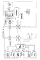
- Fig. 1 is a diagram showing the whole arrangement of an embodiment of this invention.
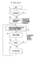
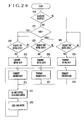
- Figs. 2(A) and 2(B) are flow charts showing the operation of the embodiment shown in Fig. 1.
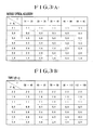
- Figs. 3 (A) and 3(B) show encoder data.
- Fig. 4 is a diagram showing the whole arrangement of another embodiment of the invention.
- Fig. 1 shows a camera system arranged according to this invention as an embodiment thereof.
- the illustration includes a camera body C; an interchangeable lens L; a tele-converter AC which is of a double magnifying power and employed as another optical accessory; a clock oscillator 2; and a power supply circuit 3 which is provided for power supply to each applicable circuit.
- a driving circuit 4 is arranged to drive an image sensor 5 such as a CCD.
- the image sensor 5 is arranged to serve also as a sensor for focusing.
- a processing circuit 6 is arranged to perform a signal processing action on the output of the image sensor 5.
- a recording device 7 is arranged to record a processed signal output from the processing circuit 6.
- a piezoelectric element 8 is arranged to vibrate the image sensor 5.
- a focusing circuit 9 is arranged to determine the lens to be in a near-focus state or in a far-focus state on the basis of image information obtained when the image sensor 5 is vibrated in the direction of an optical axis. In focusing the interchangeable lens C, information on the lens such as its focal length, its aperture value is necessary.
- a zoom operation part 10 is arranged to generate a signal indicating a telephoto position or a wide-angle position of the lens resulting from a zooming operation, which is generally performed on an external operation switch.
- a system controller 11 is arranged to perform control over the whole camera system and includes a microcomputer.
- a microcomputer 100 is arranged within the lens L to control the operation of various actuators, to communicate with the system controller 11 which is disposed within the camera body C in such a way as to send the intrinsic and variable data relative to the lens.
- a driving circuit 101 is arranged to drive a focus motor 102.
- the focus motor 102 is provided as a drive source for a focus driving mechanism and is arranged to shift the position of a focusing lens (not shown) in the direction of the optical axis.
- An encoder 103 is provided for detecting the position of the focusing lens.
- a driving circuit 104 is arranged to drive a zoom motor 105.
- the zoom motor 105 is a drive source for a zoom driving mechanism and is arranged to shift the position of a zooming lens (not shown) in the direction of the optical axis.
- An encoder 106 is provided for detecting the position of the zooming lens.
- a driving circuit 107 is provided for driving a diaphragm motor 108.
- the diaphragm motor 108 (or a drive source called "meter") is of a type varying the aperture of the diaphragm by sliding two blades or of a type varying the aperture by rotating three or four blades.
- An encoder 109 is provided for detecting an aperture value and is arranged to produce an absolute data value of the aperture obtained by detecting the movement of a working member by means of a Hall element.
- the double magnifying tele-converter AC which is employed as an optical accessory includes information output means which consists of resistors R1 and R2 and is arranged to provide the interchangeable lens L with information, in the form of a voltage, about the tele-converter's own optical characteristic indicating, for example, a changed (or adjusted) value of focal length and that of the aperture (F number).
- Mount contacts P1 to P5 are disposed on the side of the camera body C.
- the mount contact P1 is provided for the power supply (high potential).
- the mount contact P2 is for the ground.
- the mount contacts P3 to P5 are provided for communication.
- Mount contacts P17 to P22 are disposed on the side of the lens L.
- the mount contact P17 is provided for the power supply and the mount contact P18 for the ground.
- the mount contacts P19, P20 and P21 are provided for communication.
- the mount contact P22 is provided only on the side of the lens L for detection of mounting of an accessory such as the tele-converter and the kind of the accessory mounted. On the side of the camera body C, there is provided no mount contact in a position corresponding to this mount contact P22. Therefore, when the interchangeable lens L is mounted directly on the camera body C, the mount contact P22 does not come into contact with any of the mount contacts of the camera body.
- the tele-converter AC is provided with mount contacts P6 to P10 which are arranged to come into contact with the mount contacts P1 to P5 of the camera body C and is also provided with mount contacts P11 to P16 which are arranged to come into contact with the mount contacts P17 to P22 of the lens.
- the mount contacts P1 and P2 are connected to the power supply 3.
- the mount contacts P3 and P4 are connected to the system controller 11.
- the mount contact P5 is connected to the clock oscillator 2.
- the mount contacts P17 and P18 of the lens L come into contact with the mount contacts P1 and P2 of the camera body C upon completion of bayonet mounting of the interchangeable lens L on the camera body C. This allows the power to be supplied to electrical elements disposed within the lens L.
- the mount contacts P17 and P18 come into contact with the mount contacts P11 and P12.
- the mount contacts P19 to P21 of the lens L are connected to the microcomputer 100 and, upon completion of lens mounting, come into contact with the mount contacts P3 to P5 in such a way as to permit communication between the lens L and the camera body C.
- the mount contacts P19 to P21 come into contact with the mount contacts P13 to P15.
- the mount contact P22 is connected to the microcomputer 100. This contact P22 has no corresponding mount contact on the side of the camera body C. Therefore, when the lens L is mounted directly on the camera body C, the mount contact P22 receives a ground level voltage to allow detection of the fact that no such accessory as the converter or the like is mounted on the camera body C. In a case where an accessory (or the tele-converter AC) is mounted and interposed in between the lens L and the camera body C, the mount contact P22 comes into contact with the mount contact P16 of the accessory to receive voltage information on the kind of the accessory mounted.
- the mount contacts P6 to P10 are arranged to merely communicate with the mount contacts P11 to P16 respectively.
- the mount contact P16 is connected to resistors R1 and R2.
- Fig. 2(A) shows the flow of operation of the system controller 11 disposed within the camera body C.
- a check is made at a step ST1 to find if the interchangeable lens L is mounted on the camera body C. If so, the flow proceeds to a step ST2.
- the lens-mounted state is detected in one of various methods including a simple method of using a mechanical switch; and another method in which the camera is arranged to periodically inquire as to whether the lens is mounted and to determine that the lens is mounted when a reply is received.
- Initial data communication is conducted to obtain initial data for the interchangeable lens L from the microcomputer 100 of the lens L.
- the initial data to be thus received includes focal length values obtained at the telephoto end position and at the wide-angle end position of the lens; the F-number of a maximum aperture; the kind of a diaphragm mechanism: and the kind of a focusing mechanism.
- Information is obtained from the encoders 103, 106 and 109 to find the current conditions including the state of the focusing lens, that of the zooming lens and that of the diaphragm.
- the focusing circuit 9 is caused to perform a focusing action.
- the system controller 11 controls the focusing action not merely on the basis of the current degree of defocus but also considers information on a focal length which is obtained from the encoder 106 and information on an aperture value which is obtained from the encoder 109. Then, data relative to the rotating direction and speed of the focusing motor 102, etc. is sent to the microcomputer 100 of the lens L.
- the focusing action is allowed to continue until an in-focus state is determined to have been attained.
- the rotation of the focus motor 102 is brought to a stop as the in-focus state has been detected.
- step ST10 A check is made for the presence or absence of an optical accessory such as the converter on the camera body.
- the microcomputer 100 checks voltage information obtained from the mount contact P22. If this voltage is found to be at a ground level, the accessory is determined to be absent and the flow comes to a step ST18. If the voltage information is found not at the ground level, the accessory is determined to be mounted on the camera body and the flow proceeds to a step ST11.
- step ST11 A check is made for the kind of the optical accessory mounted on the camera body C. If the accessory is found to be of a type 1, the flow comes to a step ST12. If it is found to be of a type 2, the flow comes to a step ST15. In this instance, the flow of operation is described on the assumption that the optical accessories that can be mounted on the camera body C are divided into the type 1 and the type 2.
- step ST12 A check is made to find if a request has been received from the system controller 11 of the camera body C for the initial data. If so, the flow comes to a step ST13.
- step ST13 The initial data which is changed according to their use of the optical accessory of the type 1 is sent to the system controller 11. Assuming that the type 1 is the tele-converter of a double magnifying power as in the case of Fig. 1, data indicating the changed value of focal length, that of the maximum aperture F-number, etc. is sent to the system controller 11 of the camera body C. Further, the initial data to be used with the optical accessories of the types 1 and 2 is stored beforehand in the memory ROM of the microcomputer 100 of the interchangeable lens L.
- a step ST14 The encoder data which has been changed by the use of the type 1 optical accessory is sent to the camera body C. More specifically, the data values of the encoders 103, 106 and 109 are not simply sent to the camera body as they are. Their values are replaced with applicable values stored in the memory ROM before the data is sent to the system controller of the camera body.
- Fig. 3(A) shows the encoder data values to be obtained with no optical accessory mounted on the camera body.
- Fig. 3(B) shows the encoder data values applicable to a case where an optical accessory of the type 1 (the double magnifying tele-converter) is mounted on the camera body.
- this embodiment is arranged to send to the camera body not only the data of the maximum aperture value but also data for stopped-down aperture values obtained by replacing the data values with adjusted values as the encoder data.
- the aperture values which are shown as the encoder data in Fig. 3(B) are obtained by simply multiplying the normal aperture values by 2 for the use of a standard tele-converter of a double magnifying power. In cases where some close-up ring or a special converter is used, however, the aperture value varies in a complex manner.
- Steps ST15 to ST17 With the request for the initial data received from the camera body like in the case of the steps ST12 to ST14 mentioned above, the initial data is sent to the camera body with the type 2 optical accessory mounted on the camera body. Further, after that, the data of each encoder is replaced with applicable data stored by the memory ROM within the microcomputer 100 and the replacement data is also sent to the camera body.
- a step ST18 A check is made to find if a request for the initial data is received from the system controller 11 of the camera body. If so, the flow comes to a step ST19.
- the step ST19 Since no optical accessory is mounted on the camera body in this instance, the intrinsic initial data of the interchangeable lens L is read out from the memory ROM of the microcomputer 100 and is sent to the camera body.
- the encoder data for the interchangeable lens L is sent to the camera body without replacing it with any other data as no optical accessory is mounted on the camera body.
- Step ST21 Control data is received from the system controller 11 of the camera body, the data indicating, for example, that the focusing lens is to be moved at a specific speed toward the nearest distance position thereof.
- Step ST22 In accordance with the control data, the motor 102, 105 or 108 is driven accordingly.
- a microcomputer 200 is included in the optical accessory AC.
- the initial data for the use of the optical accessory AC and the encoder data are replaced with other data by this microcomputer 200.
- the interchangeable lens L has no mount contact for detecting mounting of an optical accessory and the kind of the accessory.
- the arrangement of the embodiments described in the foregoing enables a camera system of the kind permitting use of optical accessories such as a tele-converter, etc. to replace the aperture value data with data apposite to the optical accessory during the process of varying the aperture.
- the invented arrangement thus ensures accurate operations of the camera system.
- a camera system permitting mounting of an optical accessory in addition to a camera body and an interchangeable lens comprises: a diaphragm disposed within the interchangeable lens; a detecting part for detecting aperture information on a stopped down aperture obtained when the aperture of the diaphragm is stopped down; and a correction part which is arranged to correct the aperture information obtained by the detecting part when the optical accessory is mounted and to supply the corrected aperture information to the camera body.
Landscapes
- Physics & Mathematics (AREA)
- General Physics & Mathematics (AREA)
- Engineering & Computer Science (AREA)
- Multimedia (AREA)
- Signal Processing (AREA)
- Structure And Mechanism Of Cameras (AREA)
- Exposure Control For Cameras (AREA)
- Focusing (AREA)
- Lens Barrels (AREA)
- Automatic Focus Adjustment (AREA)
Applications Claiming Priority (2)
| Application Number | Priority Date | Filing Date | Title |
|---|---|---|---|
| JP2036720A JPH0786586B2 (ja) | 1990-02-17 | 1990-02-17 | カメラシステム,交換レンズ及び光学付属品 |
| JP36720/90 | 1990-02-17 |
Publications (2)
| Publication Number | Publication Date |
|---|---|
| EP0443463A1 true EP0443463A1 (de) | 1991-08-28 |
| EP0443463B1 EP0443463B1 (de) | 1997-05-02 |
Family
ID=12477584
Family Applications (1)
| Application Number | Title | Priority Date | Filing Date |
|---|---|---|---|
| EP91102203A Expired - Lifetime EP0443463B1 (de) | 1990-02-17 | 1991-02-15 | Kamera |
Country Status (5)
| Country | Link |
|---|---|
| US (1) | US5548369A (de) |
| EP (1) | EP0443463B1 (de) |
| JP (1) | JPH0786586B2 (de) |
| KR (1) | KR930011643B1 (de) |
| DE (1) | DE69125873T2 (de) |
Cited By (10)
| Publication number | Priority date | Publication date | Assignee | Title |
|---|---|---|---|---|
| EP0482997A1 (de) * | 1990-10-23 | 1992-04-29 | Sony Corporation | Objektivfassung mit Bezugswelle zur beweglichen Unterstützung einer optischen Linse |
| GB2275801A (en) * | 1993-03-03 | 1994-09-07 | Samsung Aerospace Ind | Camera control system |
| US5606392A (en) * | 1996-06-28 | 1997-02-25 | Eastman Kodak Company | Camera using calibrated aperture settings for exposure control |
| US5758212A (en) * | 1994-07-22 | 1998-05-26 | Samsung Aerospace Industries, Ltd. | Camera for shortening a strobe charge time |
| EP0942598A3 (de) * | 1998-03-11 | 2002-09-25 | Canon Kabushiki Kaisha | Verfahren und Vorrichtung zur Aufnahme von Panoramabildern, entsprechendes Kontrolverfahren und Aufzeichnungsmedium |
| EP1669785A4 (de) * | 2003-08-12 | 2006-07-26 | Olympus Corp | Kamera, wechselbare linse, zwischenadapterund kamerasystem damit |
| DE10015873B4 (de) * | 1999-03-31 | 2008-12-24 | Fujinon Corp. | Antriebseinheit für ein Linsensystem bzw. eine Kamera |
| JP2012190024A (ja) * | 2011-02-25 | 2012-10-04 | Nikon Corp | アクセサリー、カメラボディおよびカメラシステム |
| DE10262330B4 (de) * | 2001-02-19 | 2013-05-29 | Pentax Ricoh Imaging Company, Ltd. | Konverter für ein Kamerasystem |
| EP3611564A4 (de) * | 2017-05-31 | 2021-02-24 | Canon Kabushiki Kaisha | Zubehörvorrichtung, kamera, kommunikationssteuerungsprogramm und kamerasystem |
Families Citing this family (15)
| Publication number | Priority date | Publication date | Assignee | Title |
|---|---|---|---|---|
| JP3584108B2 (ja) * | 1996-01-08 | 2004-11-04 | キヤノン株式会社 | レンズ鏡筒 |
| JPH10239727A (ja) * | 1997-02-27 | 1998-09-11 | Canon Inc | 電子機器の駆動システム |
| US6341902B1 (en) * | 1997-12-05 | 2002-01-29 | Asahi Kogaku Kogyo Kabushiki Kaisha | Photographic lens recognition system for a camera body |
| US6989865B1 (en) * | 1997-12-19 | 2006-01-24 | Canon Kabushiki Kaisha | Optical equipment and it control method, and computer-readable storage medium |
| JP3836685B2 (ja) * | 2001-02-28 | 2006-10-25 | ペンタックス株式会社 | レンズ交換式カメラの通信システム |
| SE0202643D0 (sv) * | 2002-09-09 | 2002-09-09 | Hasselblad Ab Victor | Ett kamerahus med detektering och initiering av status i anslutna enheter |
| JP2007003646A (ja) * | 2005-06-22 | 2007-01-11 | Fujifilm Holdings Corp | カメラシステム、レンズユニット、及びアクセサリ |
| JP5220301B2 (ja) * | 2006-11-10 | 2013-06-26 | ペンタックスリコーイメージング株式会社 | 交換レンズ及びレンズデータ通信方法 |
| JP5168533B2 (ja) * | 2007-01-11 | 2013-03-21 | 株式会社ニコン | レンズ鏡筒及び光学システム |
| KR101476648B1 (ko) * | 2008-03-20 | 2014-12-26 | 삼성전자주식회사 | 디지털 촬영 장치 및 이의 제어 방법 |
| US7874747B2 (en) * | 2008-04-28 | 2011-01-25 | Panasonic Corporation | Intermediate adapter, camera body and imaging system |
| JP5208169B2 (ja) * | 2010-08-06 | 2013-06-12 | キヤノン株式会社 | カメラシステムの中間アクセサリおよびカメラシステム |
| JP5418552B2 (ja) * | 2011-07-22 | 2014-02-19 | 株式会社ニコン | アダプター、カメラシステム、および、アダプター制御プログラム |
| JP6674254B2 (ja) * | 2015-12-28 | 2020-04-01 | キヤノン株式会社 | レンズ装置及びそれを有する撮像装置 |
| JP7208203B2 (ja) * | 2020-09-16 | 2023-01-18 | キヤノン株式会社 | 中間アクセサリ装置、撮像装置、撮像システム、処理方法、およびプログラム |
Citations (4)
| Publication number | Priority date | Publication date | Assignee | Title |
|---|---|---|---|---|
| US4400072A (en) * | 1979-07-31 | 1983-08-23 | Canon Kabushiki Kaisha | Diaphragm device for a camera with interchangeable lenses |
| US4733258A (en) * | 1984-09-28 | 1988-03-22 | Minolta Camera Kk | Interchangeable lens camera system |
| US4758854A (en) * | 1986-02-01 | 1988-07-19 | Nippon Kogaku K.K. | Camera system |
| US4881094A (en) * | 1987-02-16 | 1989-11-14 | Nikon Corporation | Lens interchange type single-lens reflex camera system and intermediate barrel therefor |
Family Cites Families (3)
| Publication number | Priority date | Publication date | Assignee | Title |
|---|---|---|---|---|
| JP2831995B2 (ja) * | 1987-01-14 | 1998-12-02 | キヤノン株式会社 | カメラシステム及び交換レンズ |
| JPH01218268A (ja) * | 1988-02-26 | 1989-08-31 | Sony Corp | 交換レンズ装置及びカメラ装置 |
| US5079578A (en) * | 1988-10-13 | 1992-01-07 | Canon Kabushiki Kaisha | Camera system |
-
1990
- 1990-02-17 JP JP2036720A patent/JPH0786586B2/ja not_active Expired - Fee Related
-
1991
- 1991-02-11 US US07/654,074 patent/US5548369A/en not_active Expired - Lifetime
- 1991-02-13 KR KR1019910002436A patent/KR930011643B1/ko not_active Expired - Fee Related
- 1991-02-15 DE DE69125873T patent/DE69125873T2/de not_active Expired - Fee Related
- 1991-02-15 EP EP91102203A patent/EP0443463B1/de not_active Expired - Lifetime
Patent Citations (4)
| Publication number | Priority date | Publication date | Assignee | Title |
|---|---|---|---|---|
| US4400072A (en) * | 1979-07-31 | 1983-08-23 | Canon Kabushiki Kaisha | Diaphragm device for a camera with interchangeable lenses |
| US4733258A (en) * | 1984-09-28 | 1988-03-22 | Minolta Camera Kk | Interchangeable lens camera system |
| US4758854A (en) * | 1986-02-01 | 1988-07-19 | Nippon Kogaku K.K. | Camera system |
| US4881094A (en) * | 1987-02-16 | 1989-11-14 | Nikon Corporation | Lens interchange type single-lens reflex camera system and intermediate barrel therefor |
Non-Patent Citations (1)
| Title |
|---|
| PATENT ABSTRACTS OF JAPAN vol. 8, no. 254 (P-315)(1691) 21 November 1984, & JP-A-59 126522 (MINOLTA) 21 July 1984, * |
Cited By (15)
| Publication number | Priority date | Publication date | Assignee | Title |
|---|---|---|---|---|
| US5272567A (en) * | 1990-10-23 | 1993-12-21 | Sony Corporation | Lens barrel having reference shafts movably supporting lenses |
| EP0482997A1 (de) * | 1990-10-23 | 1992-04-29 | Sony Corporation | Objektivfassung mit Bezugswelle zur beweglichen Unterstützung einer optischen Linse |
| GB2275801A (en) * | 1993-03-03 | 1994-09-07 | Samsung Aerospace Ind | Camera control system |
| US5758212A (en) * | 1994-07-22 | 1998-05-26 | Samsung Aerospace Industries, Ltd. | Camera for shortening a strobe charge time |
| US5606392A (en) * | 1996-06-28 | 1997-02-25 | Eastman Kodak Company | Camera using calibrated aperture settings for exposure control |
| EP0942598A3 (de) * | 1998-03-11 | 2002-09-25 | Canon Kabushiki Kaisha | Verfahren und Vorrichtung zur Aufnahme von Panoramabildern, entsprechendes Kontrolverfahren und Aufzeichnungsmedium |
| US7136096B1 (en) | 1998-03-11 | 2006-11-14 | Canon Kabushiki Kaisha | Image processing method and apparatus, control method therefor, and storage medium |
| DE10015873B4 (de) * | 1999-03-31 | 2008-12-24 | Fujinon Corp. | Antriebseinheit für ein Linsensystem bzw. eine Kamera |
| DE10262330B4 (de) * | 2001-02-19 | 2013-05-29 | Pentax Ricoh Imaging Company, Ltd. | Konverter für ein Kamerasystem |
| DE10206913B4 (de) * | 2001-02-19 | 2013-05-29 | Pentax Ricoh Imaging Company, Ltd. | Kamerasystem mit einem Kamerakörper und einem auswechselbaren Aufnahmeobjektiv |
| EP1669785A4 (de) * | 2003-08-12 | 2006-07-26 | Olympus Corp | Kamera, wechselbare linse, zwischenadapterund kamerasystem damit |
| JP2012190024A (ja) * | 2011-02-25 | 2012-10-04 | Nikon Corp | アクセサリー、カメラボディおよびカメラシステム |
| EP3611564A4 (de) * | 2017-05-31 | 2021-02-24 | Canon Kabushiki Kaisha | Zubehörvorrichtung, kamera, kommunikationssteuerungsprogramm und kamerasystem |
| US11006031B2 (en) | 2017-05-31 | 2021-05-11 | Canon Kabushiki Kaisha | Accessory device, camera, storage medium, and camera system in which communication is performed via data and notification channels and employs differences in voltage level for the notification channel during a period in which data is received |
| EP4354892A3 (de) * | 2017-05-31 | 2024-07-31 | Canon Kabushiki Kaisha | Zubehörvorrichtung, kamera, kommunikationssteuerungsprogramm und kamerasystem |
Also Published As
| Publication number | Publication date |
|---|---|
| DE69125873T2 (de) | 1997-12-18 |
| EP0443463B1 (de) | 1997-05-02 |
| JPH03240029A (ja) | 1991-10-25 |
| KR910015879A (ko) | 1991-09-30 |
| DE69125873D1 (de) | 1997-06-05 |
| JPH0786586B2 (ja) | 1995-09-20 |
| US5548369A (en) | 1996-08-20 |
| KR930011643B1 (ko) | 1993-12-16 |
Similar Documents
| Publication | Publication Date | Title |
|---|---|---|
| US5548369A (en) | Camera | |
| US5038163A (en) | Camera system | |
| US5053798A (en) | Automatic focusing device | |
| EP0394901B1 (de) | Gerät zur Objektivsteuerung | |
| JP2714039B2 (ja) | カメラ装置 | |
| JP4035179B2 (ja) | 撮影レンズ及びそれを用いた光学機器 | |
| US20020047912A1 (en) | Camera system | |
| EP0260990A2 (de) | Fokussierungskontrolle und Informationsanzeige bezüglich eines Objektes | |
| US7193651B2 (en) | Camera system, lens apparatus and camera | |
| US6603929B2 (en) | Camera system and lens apparatus | |
| US5087978A (en) | Camera system and interchangeable lens | |
| US4912494A (en) | Camera system | |
| JP2004177919A (ja) | ズームレンズの制御装置および撮影システム | |
| EP0791844B1 (de) | Apparat zur Kontrolle eines optischen Systems | |
| JPH1123949A (ja) | 撮影レンズの画角補正装置 | |
| US5455650A (en) | Photographic converter | |
| US5748997A (en) | Control method of a zoom lens camera | |
| JP3907222B2 (ja) | 映像機器システム及び交換レンズ | |
| EP0503572B1 (de) | Optische Fokussiervorrichtung | |
| JP3276794B2 (ja) | 変換アダプター | |
| JPH09236739A (ja) | 撮像装置 | |
| US6608455B2 (en) | Driving apparatus for vibration type motor and vibration type motor driving control method | |
| JPH06205267A (ja) | 自動合焦装置 | |
| JPH0785124B2 (ja) | 自動焦点調節装置 | |
| JP2757413B2 (ja) | カメラ |
Legal Events
| Date | Code | Title | Description |
|---|---|---|---|
| PUAI | Public reference made under article 153(3) epc to a published international application that has entered the european phase |
Free format text: ORIGINAL CODE: 0009012 |
|
| AK | Designated contracting states |
Kind code of ref document: A1 Designated state(s): DE FR GB NL |
|
| 17P | Request for examination filed |
Effective date: 19920114 |
|
| 17Q | First examination report despatched |
Effective date: 19930830 |
|
| GRAG | Despatch of communication of intention to grant |
Free format text: ORIGINAL CODE: EPIDOS AGRA |
|
| GRAH | Despatch of communication of intention to grant a patent |
Free format text: ORIGINAL CODE: EPIDOS IGRA |
|
| GRAH | Despatch of communication of intention to grant a patent |
Free format text: ORIGINAL CODE: EPIDOS IGRA |
|
| GRAA | (expected) grant |
Free format text: ORIGINAL CODE: 0009210 |
|
| AK | Designated contracting states |
Kind code of ref document: B1 Designated state(s): DE FR GB NL |
|
| REF | Corresponds to: |
Ref document number: 69125873 Country of ref document: DE Date of ref document: 19970605 |
|
| ET | Fr: translation filed | ||
| PLBE | No opposition filed within time limit |
Free format text: ORIGINAL CODE: 0009261 |
|
| STAA | Information on the status of an ep patent application or granted ep patent |
Free format text: STATUS: NO OPPOSITION FILED WITHIN TIME LIMIT |
|
| 26N | No opposition filed | ||
| REG | Reference to a national code |
Ref country code: GB Ref legal event code: IF02 |
|
| PGFP | Annual fee paid to national office [announced via postgrant information from national office to epo] |
Ref country code: DE Payment date: 20090228 Year of fee payment: 19 Ref country code: NL Payment date: 20090217 Year of fee payment: 19 |
|
| PGFP | Annual fee paid to national office [announced via postgrant information from national office to epo] |
Ref country code: GB Payment date: 20090218 Year of fee payment: 19 |
|
| PGFP | Annual fee paid to national office [announced via postgrant information from national office to epo] |
Ref country code: FR Payment date: 20090223 Year of fee payment: 19 |
|
| REG | Reference to a national code |
Ref country code: NL Ref legal event code: V1 Effective date: 20100901 |
|
| GBPC | Gb: european patent ceased through non-payment of renewal fee |
Effective date: 20100215 |
|
| REG | Reference to a national code |
Ref country code: FR Ref legal event code: ST Effective date: 20101029 |
|
| PG25 | Lapsed in a contracting state [announced via postgrant information from national office to epo] |
Ref country code: FR Free format text: LAPSE BECAUSE OF NON-PAYMENT OF DUE FEES Effective date: 20100301 Ref country code: NL Free format text: LAPSE BECAUSE OF NON-PAYMENT OF DUE FEES Effective date: 20100901 |
|
| PG25 | Lapsed in a contracting state [announced via postgrant information from national office to epo] |
Ref country code: DE Free format text: LAPSE BECAUSE OF NON-PAYMENT OF DUE FEES Effective date: 20100901 |
|
| PG25 | Lapsed in a contracting state [announced via postgrant information from national office to epo] |
Ref country code: GB Free format text: LAPSE BECAUSE OF NON-PAYMENT OF DUE FEES Effective date: 20100215 |