EP0443482A1 - Anordnung zum Anschluss digitaler Endstationen an eine einzige Schnittstelle höherer Geschwindigkeit - Google Patents
Anordnung zum Anschluss digitaler Endstationen an eine einzige Schnittstelle höherer Geschwindigkeit Download PDFInfo
- Publication number
- EP0443482A1 EP0443482A1 EP91102263A EP91102263A EP0443482A1 EP 0443482 A1 EP0443482 A1 EP 0443482A1 EP 91102263 A EP91102263 A EP 91102263A EP 91102263 A EP91102263 A EP 91102263A EP 0443482 A1 EP0443482 A1 EP 0443482A1
- Authority
- EP
- European Patent Office
- Prior art keywords
- interface
- terminals
- useful
- speed
- transmission
- Prior art date
- Legal status (The legal status is an assumption and is not a legal conclusion. Google has not performed a legal analysis and makes no representation as to the accuracy of the status listed.)
- Withdrawn
Links
- 230000005540 biological transmission Effects 0.000 claims abstract description 36
- 238000009434 installation Methods 0.000 claims abstract description 11
- 238000004804 winding Methods 0.000 description 5
- 230000011664 signaling Effects 0.000 description 4
- 230000001360 synchronised effect Effects 0.000 description 2
- 238000010586 diagram Methods 0.000 description 1
- 238000000034 method Methods 0.000 description 1
- 230000033764 rhythmic process Effects 0.000 description 1
Images

Classifications
-
- H—ELECTRICITY
- H04—ELECTRIC COMMUNICATION TECHNIQUE
- H04L—TRANSMISSION OF DIGITAL INFORMATION, e.g. TELEGRAPHIC COMMUNICATION
- H04L5/00—Arrangements affording multiple use of the transmission path
- H04L5/14—Two-way operation using the same type of signal, i.e. duplex
- H04L5/1469—Two-way operation using the same type of signal, i.e. duplex using time-sharing
- H04L5/1484—Two-way operation using the same type of signal, i.e. duplex using time-sharing operating bytewise
- H04L5/1492—Two-way operation using the same type of signal, i.e. duplex using time-sharing operating bytewise with time compression, e.g. operating according to the ping-pong technique
-
- H—ELECTRICITY
- H04—ELECTRIC COMMUNICATION TECHNIQUE
- H04L—TRANSMISSION OF DIGITAL INFORMATION, e.g. TELEGRAPHIC COMMUNICATION
- H04L5/00—Arrangements affording multiple use of the transmission path
- H04L5/22—Arrangements affording multiple use of the transmission path using time-division multiplexing
- H04L5/24—Arrangements affording multiple use of the transmission path using time-division multiplexing with start-stop synchronous converters
-
- H—ELECTRICITY
- H04—ELECTRIC COMMUNICATION TECHNIQUE
- H04Q—SELECTING
- H04Q11/00—Selecting arrangements for multiplex systems
- H04Q11/04—Selecting arrangements for multiplex systems for time-division multiplexing
- H04Q11/0428—Integrated services digital network, i.e. systems for transmission of different types of digitised signals, e.g. speech, data, telecentral, television signals
- H04Q11/0435—Details
- H04Q11/0471—Terminal access circuits
-
- H—ELECTRICITY
- H04—ELECTRIC COMMUNICATION TECHNIQUE
- H04Q—SELECTING
- H04Q2213/00—Indexing scheme relating to selecting arrangements in general and for multiplex systems
- H04Q2213/031—PCM
-
- H—ELECTRICITY
- H04—ELECTRIC COMMUNICATION TECHNIQUE
- H04Q—SELECTING
- H04Q2213/00—Indexing scheme relating to selecting arrangements in general and for multiplex systems
- H04Q2213/034—Codec; PCM compression
-
- H—ELECTRICITY
- H04—ELECTRIC COMMUNICATION TECHNIQUE
- H04Q—SELECTING
- H04Q2213/00—Indexing scheme relating to selecting arrangements in general and for multiplex systems
- H04Q2213/197—Ping-pong transmission
Definitions
- the invention relates to an arrangement intended to allow the connection of digital terminals with useful low bit rate to a port of a telecommunications installation which is intended to serve a terminal having a clearly higher useful bit rate, in particular in the case of a transmission carried out in asynchronous and alternating mode.
- the performances currently authorized by telecommunications installations in particular at the level of connection networks and transmission links allow the communication of digital terminals, mono or multiservices, at high useful bit rates.
- connection ports of the terminals to the installations are initially designed to be able to transmit data with a maximum speed.
- Each port therefore has a digital interface arranged to allow the connection of a terminal whose useful speed possibly corresponds to this maximum speed, or failing this a compatible terminal with a lower useful speed. This generally results in the study, the realization and the marketing of more or less different interfaces.
- the invention therefore proposes an arrangement intended to allow the connection of digital terminals with low useful data rate to a transmission interface of a port of telecommunications installation which is designed to serve a terminal having a significantly higher useful rate, in particularly in the case of a transmission carried out in asynchronous mode and in the half-cycle, and this in order to be able to exploit the same transmission interfaces, at the access ports to the facilities, for different terminals with compatible online speeds.
- the arrangement comprises means for reserving periods of time equal to each frame for an alternation exchange between the high speed transmission interface of the port and each of the useful low speed terminals served by this interface.
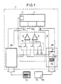
- Figure 1 shows a diagram of a connection arrangement according to the invention.
- FIG. 2 shows an example of a conventional frame structure for a point-to-point digital transmission link operated in the half-board.
- FIG. 3 shows an example of a frame structure compatible with the previous one intended for serving at least two terminals in parallel at one of the two points of a point-to-point digital transmission link operated in the half-board.
- the arrangement according to the invention is provided to allow the connection of at least two digital terminals 1A, 1B to a high speed interface 2 of one of the ports for terminals of a telecommunications installation, for example a telephone switch.
- These terminal ports usually give access to the connection and signaling structures of the installation which are for example of the bus or network type and which allow the establishment of communications between compatible terminals and the exchange of signaling.
- a high speed interface such as 2 is designed to be able to serve a useful high speed data terminal; in the case of a transmission carried out in asynchronous mode and in the half-cycle, according to the invention, this interface is also capable of serving parallel terminals, such as 1A and 1B, having significantly lower useful bit rates than that for which they are substituted.
- a large number of conventional digital transmission ports are designed to transmit digital data synchronously and / or asynchronously, during successive frames of the same duration, themselves divided into the same number of equal time intervals each reserved for the transmission of the same number of data, for example a byte.
- CITT International Committee
- the operating structure is based on a division of time into a succession of frames which have a duration of 125 ⁇ s and which each are divided into thirty two time intervals corresponding to as many isochronous channels of transmission.
- the first time interval of each frame is reserved for the transmission of service bytes and in particular for the frame synchronization bits.
- the successive frames make it possible to transmit bytes of synchronous signals, in particular samples of speech signals for a communication established in real time, from the moment when a time interval is reserved during each of the successive frames for the duration of the communication.
- the time intervals having the same frame rank during successive frames define a channel capable of being exploited for digital transmission purposes.
- the frame mentioned above also makes it possible to transmit data asynchronously in the form of packets or cells, the bytes of each packet or cells are conventionally preceded by service bytes.
- the first time interval of each frame conventionally allows the transmission of the frame synchronization bits, a following interval being usually assigned to the signaling to be transmitted.
- Such a frame structure is in particular used in the half-board to allow exchanges between two transmitter-receiver units, in particular between the interface 2 which has a port and a terminal connected point-to-point to this interface.
- each transmitting unit transmits, in turn and at each frame, a succession of data preceded by a header comprising service bytes, conventionally a first synchronization byte here referenced FS , and at least one signaling byte, referenced Sg, between which are possibly provided a determined number of synchronous signal bytes, referenced B1 for one channel and B2 for another.
- a header comprising service bytes, conventionally a first synchronization byte here referenced FS , and at least one signaling byte, referenced Sg, between which are possibly provided a determined number of synchronous signal bytes, referenced B1 for one channel and B2 for another.
- Bytes B1 are for example speech samples
- bytes B2 are for example data bytes.
- the last byte Sg of the header for a frame is followed by a limited number of message or cell bytes, such as those of the M1 message, as needed and depending on the frame time remaining available for the unit active transmitter, for example the interface 2, which then stops transmitting to allow the terminal to transmit in turn according to an identical or similar process.
- Each transmitting unit therefore has the possibility of transmitting once per frame, each of the two transmissions in the opposite direction being separated by a short period of time, referenced LT and known as link reversal, making it possible to switch alternately each of the two transmitting units d 'an active state to a passive state.
- each unit during the frames is carried out at the rhythm fixed by a clock which is either the clock 11 that includes the broadband interface 2, a clock of the same frequency and possibly the same phase, such as 11B for terminal 1B, which each of the terminals concerned comprises.
- the transmissions are liable to vary in duration depending on the length of the messages to be transmitted, and this from a minimum value corresponding to the single transmission of the header bytes, as indicated in connection with the frames T1, T2 and T3 in the figure. 2.
- the transmitting unit conventional and not shown, contained in a terminal, such as 1A, and a transmitting unit 6A associated with the high-speed interface 3 in an installation 4, are alternately activated and successively send binary data transcoded into online transmission code and organized by byte to respectively a receiving unit 7AB associated with the broadband interface 3 and a receiving unit not shown from terminal 1A.
- the two transmissions occurring successively during this first part of the frame which therefore each come from a different transmitting unit, are separated by a link reversal time LT.
- Each transmission identically includes a header whose composition is identical to that of the header mentioned above, the unit 6A being assumed to be the first in transmission in FIG. 3.
- one of the two transmitting units defined above transmits a header possibly followed by the bytes of a packet, at the start of the second half of frame, only the bytes of head FS, B1, B2, Sg being represented in FIG. 3 both for the various first half-frames and for the seconds.
- the second unit transmits header bytes possibly followed by message bytes also, the transmitting unit 6B being assumed to be first to transmit, before the transmitting unit of terminal 1B.
- connection arrangement according to the invention therefore comprises a high speed interface 2 making it possible to connect one of the ports of an installation 4 to terminals with low useful speed, such as 1A and 1B.
- a high-speed interface 2 appears in French patent 2,517,908 of the applicant, it will therefore not be developed here insofar as the structure of this interface is not in itself the subject of the present invention.
- the interface 2 which is intended to be served by a transmitting unit and by a receiving unit for its exchanges with a broadband terminal, is here connected to as many transmitting units as there are low-speed terminals served, either here two transmitting units 6A and 6B, as well as a common receiving unit 7AB. These units are for example of the type described in French patent 2542531 of the applicant.
- Each transmitting unit 6A, 6B is connected here by two wires to a line interface, such as 8A or 8B, to which a useful low speed terminal 1A or 1B is connected.
- a line interface is arranged for example in the manner presented in FIG. 3, the two wires emanating from the corresponding transmitting unit coming each to be connected to one of the two end terminals of a first winding 91 of a transformer.
- the second winding 92 of the transformer is connected to the transmitting unit and to the receiving unit, not shown, of terminal 1B, via a two-wire line, the two wires of which each terminate at one of the end terminals of this second winding .
- the transmitting unit and the receiving unit of each useful low-speed terminal are for example of the same type as Your units 6A, 7AB.
- the receiving unit 7AB is connected by a switching unit 12 to each of the line interfaces 8A, 8B.
- This switching unit 12 is connected to the two inputs of the receiving unit 7AB by two comparators 13, 14 capable of being each connected by a first input to a different end of the first winding 91 of alternately each of the line interfaces, by a switching device 15.
- the latter which includes as many stable states as there are terminals served by the broadband interface 2 considered, also connects a second input of each of the comparators 13 and 14 to a reference potential , here VA or VB, depending on the transmission characteristics of the line connecting each terminal to its line interface.
- a resistor 10 connecting the ends of the winding 91, beyond the connection points C, D common to the transmitter 6B and to the switching unit 12, conventionally provides impedance matching.
- member 15 The switching operations of member 15 are controlled by the clock, not shown, of the high-speed interface 2 which supplies signals calibrated with respect to the frame signal and whose frequency is a multiple of the frame frequency Te multiplication factor chosen being equal to the number of useful low speed terminals simultaneously served by the high speed interface considered.
- a trivial intervention on the management software of the high-speed interface 2 allows taking into account both on transmission and on reception of the bytes respectively exchanged with one or other of the terminals concerned during each of the successive half-frames.
- the two comparators 13 and 14 are alternately connected once to each frame with each of the line interfaces 8A or 8B, for the purpose of receiving the bits coming from the terminal 1A or 1B connected to this interface, during the half frame reserved for dialogue between the useful low-speed terminal considered and the high-speed interface 2.
- the latter is activated accordingly to successively transmit a header optionally followed by message bytes, at the start of each half-frame and alternately to one and then the other of the terminals.
- the receiving terminal 1A or 1B in turn transmits to the receiving unit 7AB, during the same half-frame and after, on the one hand, the end of the transmission which comes to it from the transmitting unit 6A or 6B to which it is linked and, on the other hand, a delay corresponding to the link reversal time LT.
- terminals can have a simplified transmission structure, for example in the absence of isochronous signals or in the absence of packet data to be transmitted.
- the same terminal may possibly be connected to two different line interfaces linked to the same high-speed interface, if necessary.
Landscapes
- Engineering & Computer Science (AREA)
- Signal Processing (AREA)
- Computer Networks & Wireless Communication (AREA)
- Communication Control (AREA)
- Data Exchanges In Wide-Area Networks (AREA)
Applications Claiming Priority (2)
| Application Number | Priority Date | Filing Date | Title |
|---|---|---|---|
| FR9002123 | 1990-02-21 | ||
| FR9002123A FR2658690B1 (fr) | 1990-02-21 | 1990-02-21 | Agencement de raccordement de terminaux numeriques a un meme port ayant un debit superieur. |
Publications (1)
| Publication Number | Publication Date |
|---|---|
| EP0443482A1 true EP0443482A1 (de) | 1991-08-28 |
Family
ID=9393978
Family Applications (1)
| Application Number | Title | Priority Date | Filing Date |
|---|---|---|---|
| EP91102263A Withdrawn EP0443482A1 (de) | 1990-02-21 | 1991-02-18 | Anordnung zum Anschluss digitaler Endstationen an eine einzige Schnittstelle höherer Geschwindigkeit |
Country Status (2)
| Country | Link |
|---|---|
| EP (1) | EP0443482A1 (de) |
| FR (1) | FR2658690B1 (de) |
Cited By (2)
| Publication number | Priority date | Publication date | Assignee | Title |
|---|---|---|---|---|
| FR2682248A1 (fr) * | 1991-10-03 | 1993-04-09 | Alcatel Business Systems | Procede d'echange d'informations pour agencement comportant des terminaux numeriques relies par une meme liaison a un port d'installation telephonique. |
| FR2704378A1 (fr) * | 1993-04-21 | 1994-10-28 | Dassault Automatismes Telecomm | Installation téléphonique à ligne de transmission numérique à débit réduit. |
Citations (2)
| Publication number | Priority date | Publication date | Assignee | Title |
|---|---|---|---|---|
| US3866175A (en) * | 1974-04-24 | 1975-02-11 | Ncr Co | Data communication system between a central computer and a plurality of data terminals |
| EP0292686A2 (de) * | 1987-04-29 | 1988-11-30 | Gte Laboratories Incorporated | Kompensationsanordnung für die Leitungsverzögerung von digitalen Übertragungssystemen mit Niederleistung-Leitungstreibern |
Family Cites Families (1)
| Publication number | Priority date | Publication date | Assignee | Title |
|---|---|---|---|---|
| JPS60178747A (ja) * | 1984-02-24 | 1985-09-12 | Meidensha Electric Mfg Co Ltd | 1対多数式デ−タ通信方法 |
-
1990
- 1990-02-21 FR FR9002123A patent/FR2658690B1/fr not_active Expired - Lifetime
-
1991
- 1991-02-18 EP EP91102263A patent/EP0443482A1/de not_active Withdrawn
Patent Citations (2)
| Publication number | Priority date | Publication date | Assignee | Title |
|---|---|---|---|---|
| US3866175A (en) * | 1974-04-24 | 1975-02-11 | Ncr Co | Data communication system between a central computer and a plurality of data terminals |
| EP0292686A2 (de) * | 1987-04-29 | 1988-11-30 | Gte Laboratories Incorporated | Kompensationsanordnung für die Leitungsverzögerung von digitalen Übertragungssystemen mit Niederleistung-Leitungstreibern |
Non-Patent Citations (1)
| Title |
|---|
| PATENT ABSTRACTS OF JAPAN vol. 10, no. 16 (E-375)(2073) 22 janvier 1986, & JP-A-60 178747 (MEIDENSHA K. K.) 12 septembre 1985, * |
Cited By (3)
| Publication number | Priority date | Publication date | Assignee | Title |
|---|---|---|---|---|
| FR2682248A1 (fr) * | 1991-10-03 | 1993-04-09 | Alcatel Business Systems | Procede d'echange d'informations pour agencement comportant des terminaux numeriques relies par une meme liaison a un port d'installation telephonique. |
| FR2704378A1 (fr) * | 1993-04-21 | 1994-10-28 | Dassault Automatismes Telecomm | Installation téléphonique à ligne de transmission numérique à débit réduit. |
| WO1995029569A1 (fr) * | 1993-04-21 | 1995-11-02 | Dassault Automatismes Et Telecommunications | Installation telephonique a ligne de transmission numerique a debit reduit |
Also Published As
| Publication number | Publication date |
|---|---|
| FR2658690A1 (fr) | 1991-08-23 |
| FR2658690B1 (fr) | 1992-04-30 |
Similar Documents
| Publication | Publication Date | Title |
|---|---|---|
| EP0034514B1 (de) | Digitale Zeitvielfach-Vermittlungsanlage für Leitungen mit Sprach- und Datenpaketübertragungen | |
| EP0493176B1 (de) | Vorrichtung zur Übertragung von Signalisierungsdaten in einem asynchronen Netz, insbesondere ATM-Netz, wobei diese Daten kanalweise in einem Multirahmen zusammengefasst und synchron, ausserhalb des Bandes übertragen werden | |
| EP0036808B1 (de) | Konzentrator für Kommunikationssystem zum Anschliessen mehrerer asynchroner Telematik-Terminals | |
| FR2748172A1 (fr) | Equipement d'adaptation de protocole pour poste telephonique et poste equipe d'un tel equipement | |
| CA1219386A (fr) | Systeme de multiplexage numerique temporel asynchrone a bus distribue | |
| EP0218499B1 (de) | Multiplexier- und Demultiplexiervorrichtungen für digitale synchrone Verbindungen mit veränderlichem Debit und Modulationsgeschwindigkeit | |
| EP0254920B1 (de) | System zum Anschluss von Telefonteilnehmern, rund um eine digitale Zeitmultiplexvermittlungsanlage gestaltet | |
| EP0487042B1 (de) | Zeitmultiplexkoppelanordnung mit verteilter Architektur und einem Verbindungsmodul zur Bildung dieser Anordnung | |
| EP0179715B1 (de) | Schnittstellenanordnung zum Anschluss einer digitalen Einrichtung an eine Zeitmultiplexverbindung | |
| EP0443482A1 (de) | Anordnung zum Anschluss digitaler Endstationen an eine einzige Schnittstelle höherer Geschwindigkeit | |
| EP0643505B1 (de) | Mehrere Bitraten enthaltender Rahmen für ein verzweigtes sternförmiges Telekommunikationsnetzwerk | |
| EP0161162B1 (de) | Automatische Vermittlungsanlage mit Video-Schaltmatrix | |
| EP0467744A1 (de) | Verfahren und Vorrichtung zur Busübertragung | |
| EP0466590B1 (de) | Digitales Kommunikationssystem für eine digitale dienstintegrierte Fernsprechanlage | |
| EP0610106B1 (de) | Signalierungsverarbeitungssystem für gemeinsame Unterstützung der Durchschaltebetriebsart in einer Telekommunikationsanlage | |
| FR2472319A1 (fr) | Station d'abonne multiservice | |
| EP0530098B1 (de) | Verfahren und Anordnung für Nachrichtenübertragung zwischen Geräten einer Kommunikationsanlage | |
| FR2665314A1 (fr) | Reseau d'interconnexion pour cóoeur d'installation de communication et installation dotee d'un tel reseau. | |
| FR2529415A1 (fr) | Systeme de transmission, sur support physique en fibre optique, d'un flux de donnees principal et d'un flux de donnees secondaire | |
| EP0250276B1 (de) | Schnittstelle zwischen einer Datenübertragungseinrichtung und mehreren Datenendeinrichtungen | |
| FR2682248A1 (fr) | Procede d'echange d'informations pour agencement comportant des terminaux numeriques relies par une meme liaison a un port d'installation telephonique. | |
| EP1047254A1 (de) | Verbindungssystem zwischen einem analogen Endgerät und einer analogen Fernsprechanlage | |
| FR2725095A1 (fr) | Dispositif de commutation de mots binaires contenus dans des cellules du type atm composite, et noeud d'acces en mode atm comprenant un tel dispositif | |
| EP0963123A1 (de) | Vermittlungsanlage mit einem Signalierungskommunikationskoppler und Verfahren zum Senden von einer Signalierungsnachricht | |
| FR2771878A1 (fr) | Procede pour interconnecter deux ensembles locaux de communication a travers un reseau de transmission, et equipement de connexion correspondant |
Legal Events
| Date | Code | Title | Description |
|---|---|---|---|
| PUAI | Public reference made under article 153(3) epc to a published international application that has entered the european phase |
Free format text: ORIGINAL CODE: 0009012 |
|
| AK | Designated contracting states |
Kind code of ref document: A1 Designated state(s): AT BE CH DE DK ES FR GB IT LI NL SE |
|
| 17P | Request for examination filed |
Effective date: 19911028 |
|
| STAA | Information on the status of an ep patent application or granted ep patent |
Free format text: STATUS: THE APPLICATION IS DEEMED TO BE WITHDRAWN |
|
| 18D | Application deemed to be withdrawn |
Effective date: 19930831 |