EP0443538B1 - Pomme de douche - Google Patents
Pomme de douche Download PDFInfo
- Publication number
- EP0443538B1 EP0443538B1 EP91102387A EP91102387A EP0443538B1 EP 0443538 B1 EP0443538 B1 EP 0443538B1 EP 91102387 A EP91102387 A EP 91102387A EP 91102387 A EP91102387 A EP 91102387A EP 0443538 B1 EP0443538 B1 EP 0443538B1
- Authority
- EP
- European Patent Office
- Prior art keywords
- nozzle
- support plate
- shower head
- head according
- cross
- Prior art date
- Legal status (The legal status is an assumption and is not a legal conclusion. Google has not performed a legal analysis and makes no representation as to the accuracy of the status listed.)
- Expired - Lifetime
Links
- 239000007788 liquid Substances 0.000 claims description 17
- 230000002093 peripheral effect Effects 0.000 claims description 15
- XLYOFNOQVPJJNP-UHFFFAOYSA-N water Substances O XLYOFNOQVPJJNP-UHFFFAOYSA-N 0.000 claims description 14
- 230000004323 axial length Effects 0.000 claims description 10
- 230000000295 complement effect Effects 0.000 claims description 3
- 239000013013 elastic material Substances 0.000 claims description 3
- 239000007921 spray Substances 0.000 description 6
- 238000004140 cleaning Methods 0.000 description 5
- 230000000694 effects Effects 0.000 description 5
- 239000000463 material Substances 0.000 description 4
- 230000015572 biosynthetic process Effects 0.000 description 3
- 239000004033 plastic Substances 0.000 description 2
- 229920003023 plastic Polymers 0.000 description 2
- 238000007789 sealing Methods 0.000 description 2
- 238000010276 construction Methods 0.000 description 1
- 230000006378 damage Effects 0.000 description 1
- 230000005489 elastic deformation Effects 0.000 description 1
- 239000012530 fluid Substances 0.000 description 1
- 238000000034 method Methods 0.000 description 1
- 230000000284 resting effect Effects 0.000 description 1
- 238000007493 shaping process Methods 0.000 description 1
- 239000007787 solid Substances 0.000 description 1
- 239000008399 tap water Substances 0.000 description 1
- 235000020679 tap water Nutrition 0.000 description 1
Images
Classifications
-
- B—PERFORMING OPERATIONS; TRANSPORTING
- B05—SPRAYING OR ATOMISING IN GENERAL; APPLYING FLUENT MATERIALS TO SURFACES, IN GENERAL
- B05B—SPRAYING APPARATUS; ATOMISING APPARATUS; NOZZLES
- B05B1/00—Nozzles, spray heads or other outlets, with or without auxiliary devices such as valves, heating means
- B05B1/14—Nozzles, spray heads or other outlets, with or without auxiliary devices such as valves, heating means with multiple outlet openings; with strainers in or outside the outlet opening
- B05B1/18—Roses; Shower heads
- B05B1/185—Roses; Shower heads characterised by their outlet element; Mounting arrangements therefor
-
- B—PERFORMING OPERATIONS; TRANSPORTING
- B05—SPRAYING OR ATOMISING IN GENERAL; APPLYING FLUENT MATERIALS TO SURFACES, IN GENERAL
- B05B—SPRAYING APPARATUS; ATOMISING APPARATUS; NOZZLES
- B05B15/00—Details of spraying plant or spraying apparatus not otherwise provided for; Accessories
- B05B15/50—Arrangements for cleaning; Arrangements for preventing deposits, drying-out or blockage; Arrangements for detecting improper discharge caused by the presence of foreign matter
- B05B15/52—Arrangements for cleaning; Arrangements for preventing deposits, drying-out or blockage; Arrangements for detecting improper discharge caused by the presence of foreign matter for removal of clogging particles
- B05B15/528—Arrangements for cleaning; Arrangements for preventing deposits, drying-out or blockage; Arrangements for detecting improper discharge caused by the presence of foreign matter for removal of clogging particles by resilient deformation of the nozzle
Definitions
- the invention relates to a shower head, comprising a shower head with an inlet and an outlet, a shower base releasably attached to the shower body and closing the outlet, and a rubber-elastic nozzle plate resting on a fixed support plate of the shower base with a plurality of molded-on elastic nozzle projections which engage in corresponding receiving bores Intervene support plate, have a greater axial length than the associated receiving bores of the support plate and protrude beyond the outer surface of the support plate even when not subjected to liquid pressure with elastically deformable ends.
- a self-cleaning effect is to be achieved for the nozzle projections referred to there as tubes.
- the nozzle projections are designed as relatively thin-walled tubes, the downstream part of which collapses or collapses in the depressurized state and closes the respective jet outlet opening.
- the passage openings should be largely sealed off from the atmosphere, so that the water present in the shower head cannot dry out with the formation of limescale deposits.
- the thin-walled tubes are to be elastically widened, so that any possible incrustation flakes off at the initial stage and should be flushed out with the shower water.
- this known shower head may have the desired self-cleaning effect
- the use of thin-walled tubular nozzle projections is disadvantageous for the spray pattern generated with the shower head.
- the thin-walled nozzle projections experience different elastic expansions depending on the water pressure. At low pressures, the emerging jet is restricted by the thin-walled nozzle projections, while at higher pressures the expansion of the nozzle projections can go so far that the water jet is no longer adequately guided through the nozzle projections. It is therefore obvious that ange sight that usually within acceptable limits such as 0.5 and 5 bar changing water pressures, an acceptable spray pattern cannot be achieved with this known shower head.
- the liquid fluid in the nozzle projections is automatically and elastically adapted to the dimensions of the liquid channels in order to ensure that even with small ones Liquid pressures the emerging jet remains spread out and the individual streams do not unite into a single coarse jet shortly after exiting the shower head.
- the elastically expanding or contracting liquid channels in the nozzle projections are also intended to achieve a self-cleaning effect for the shower head, so that solids are discharged and limescale deposits are broken up and rinsed out through the nozzle openings.
- the self-cleaning effect of this known shower head is not sufficient, in particular in the case of hard to very hard tap water, in order to remove the rapidly and massively forming limescale deposits or to reduce the extent to which the jet formation does not interfere.
- the deposits which form directly on the outside of the nozzle openings are not or only inadequately removed by the self-cleaning action of the known shower head.
- the invention has for its object to provide an improved shower head, in which the nozzle projections at the usual water pressures do not experience any deformation impairing the spray pattern and in which a complete, but at least extensive removal of the outer scale deposits at the nozzle openings is still possible.
- the task is solved based on the type of shower head specified at the outset in that the nozzle projections are thick-walled at their jet-forming outlet ends and are dimensionally stable against water pressures of up to 5 bar, but are deformable from the outside by mechanical action, with the nozzle projections at the outlet end from the
- the cross-sectional area formed outside diameter is 7 to 10 times as large as the exit cross-sectional area formed from the clear width of the jet outlet opening, that the nozzle plate with the integrally molded nozzle projections is formed from a rubber-elastic material with a Shore hardness of 40 to 50 and that the elastically deformable ends of the nozzle protrusions protrude by 1 to 2 times the outer diameter of the nozzle protrusions over the outer surface of the support plate.
- the nozzle projections are not widened by the water pressure on the one hand because of their thick walls and the specified material selection at their jet-forming outlet ends, so that they deliver a well-guided water jet with a defined jet pattern under all operating conditions.
- the nozzle projections always protrude beyond the outer surface of the support plate of the shower base so that the protruding ends, even when the shower head is not used, ie when the shower head does not have water flowing through it For example, they are exposed to the hand or fingers of the user and can be compressed and / or bent by elastic deformation by hand, while opposing the mechanical external deformation action due to their design and their material with an eraser-like resistance.
- the nozzle plate can be easily made from a suitable, relatively soft rubber material. Correspondingly soft elastomeric plastics are also suitable.
- the liquid channels in the nozzle projections are advantageously designed as stepped bores, with a larger inlet cross section and a smaller outlet cross section. If the axial length range of the larger inlet cross-section of the liquid channels protrudes beyond the outer surface of the support plate, the elastic deformability of the ends of the nozzle projections projecting beyond the outer surface of the support plate is further increased, which further removes any deposits from the liquid channels and / or at the outlet openings facilitated.
- the nozzle projections are appropriately rounded at their ends.
- the support plate can be flat and provided with receiving bores aligned parallel to one another.
- the support plate is preferably curved outwards at least on its support surface for the rubber-elastic nozzle plate, the receiving bores being arranged to diverge from one another in the flow direction starting from the support surface.
- the nozzle plate is clamped at its peripheral edge between an annular surface of the shower body and the support plate with the shower base attached to the shower body.
- a pressure ring is inserted between the annular surfaces of the shower body and the peripheral edge of the nozzle plate. If the shower base is screwed to the shower body using a circumferential thread engagement, the pressure ring ensures that the circumferential edge of the rubber-elastic nozzle plate is not carried along in the circumferential direction by friction, as a result of which shear stresses on the nozzle projections engaging in the receiving bores of the support plate are avoided.
- the shower head can also be designed in such a way that it does not generate a geometrically defined spray pattern, but rather that the spray pattern can be adjusted for different propagation.
- the support plate of the shower base is designed to be elastically deflectable and engages with a threaded part concentrically attached to it with a complementary threaded part attached to the shower body to achieve different curvatures of the support plate.
- the curvature of the support plate is more or less large, corresponding to a larger or smaller beam spread.
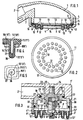
- the simple shower head shown in FIG. 1 in a first embodiment is essentially composed of a shower body 1 with inlet 2 and outlet 3 and a shower base 4.
- the shower base 4 has a cylindrical peripheral edge 5 with an internal thread, with which it is screwed onto a cylindrical ring projection 6 of the shower body 1 provided with a corresponding external thread.
- the annular projection 6 surrounds the outlet 3 of the shower body 1.
- the inlet 2 is located in a lateral projection 7 of the shower body 1, which is intended for connecting a feed line (not shown) and possibly a handle (not shown) which communicates with the inlet 2 .
- a fixed support plate 8 closing the outlet 3 is connected in one piece.
- the support plate 8 is curved in the example shown for beam expansion outwards and has two concentric circular rows of receiving bores 9, which are arranged slightly diverging from each other according to the curvature of the support plate 8 in the flow direction.
- the receiving bores 9 can also be arranged in a different geometric configuration depending on the desired properties of the shower jet.
- the central area of the support plate 8 is shown as a closed wall.
- receiving bores can also be provided in this area.
- the support plate 8 is overall with provided with a curvature. For the intended purpose of expanding the jet, it would, however, be sufficient if only its inner surface, which serves as a support surface 10 for the nozzle plate 11, which will be described in more detail below, has a curvature.
- the nozzle plate 11 made of a relatively soft rubber or a corresponding elastomeric plastic has a number of molded-on elastic nozzle projections 12 corresponding to the number of receiving bores 9 in the support plate 8, the mutual distances and the diameter of which are dimensioned such that the nozzle projections 12 into the assigned receiving holes 9 can be inserted.
- the nozzle plate 11 can be manufactured as a flat component because, due to its material elasticity, it can easily adapt to the curvature of the support plate 8.
- the liquid channels 13 in the nozzle projections 12, the orientation of which is predetermined by the axial direction of the receiving bores 9 when the nozzle plate 11 is attached to the support plate 8, are designed as simple stepped bores in the example shown, the larger diameter area of the stepped bore facing the interior of the shower body 1 is, while the smaller diameter areas of the stepped bore form the nozzle outlet cross-section.
- the axial length of the elastic nozzle projections 12 is substantially greater than that of the associated receiving bores 9, as a result of which the nozzle projections 12 with their outer ends protrude clearly beyond the outer surface 14 of the support plate 8.
- the outer ends of the nozzle projections 12 can therefore be easily deformed elastically by a slight external force, which means that they can be easily freed of any scale deposits. For this it may be sufficient if the shower head with the outer surface 14 is pulled past a suitable edge of the shower device, the outer ends of the nozzle projections are successively deformed and elastically returned to their starting position. It is therefore not absolutely necessary to deform the nozzle projections directly by hand or fingers.
- the nozzle plate 11 is firmly clamped with its peripheral edge between the ring surface 15 of the ring projection 6 and the support plate 8, the clamping resulting when the shower base 4 is screwed onto the shower body 1.
- a pressure ring 16 is inserted between the ring surface 15 and the nozzle plate 11, with the aid of which it is prevented that relative movements between the ring projection 6 and the support plate 8 are transmitted to the elastic nozzle plate 11 during screwing movements of the shower base 4.
- the pressure ring 16 rests on the nozzle plate 11 and takes part in the screwing movements of the shower base 4, whereby it slides on the ring surface 15 when it reaches it when screwing it on, or when it separates from it when unscrewing it.
- the nozzle plate 11 is provided on its peripheral edge with an annular rib 17 which engages in a corresponding annular groove 18 in the support plate 8. This engagement ensures that the nozzle plate 11 is also positively connected in its edge region to the support plate 8, this form fit not being lost even when the peripheral edge of the nozzle plate 11 is clamped in.
- a shower head in which the angle of propagation of the emerging shower jet can be set within certain limits.
- a corresponding cylindrical projection 20 of a cup-shaped housing part 21 is inserted in a cylindrical opening 19 of the shower body 1 'in a sealed manner by means of an O-ring seal 22.
- the cylinder projection 20 is the End face of an inner and cylindrical fastening projection 23 of the shower body 1 'arranged coaxially to the housing part 21.
- the fastening projection 23 is provided with a central threaded bore 24, into which a stepped bolt 26 with a threaded pin 25 for fastening the housing part 21 to the shower body 1 'is screwed.
- the stepped bolt 26 is passed through a correspondingly stepped inner bore 27 of the housing part 21 and, with an annular surface 28, rests against an annular projection 29 of the housing part 21 protruding radially inward from the inner bore 27.
- the fastening projection 23 is arranged such that it does not hinder the flow through the shower head emanating from the inlet 2 '.
- the inlet 2 ' communicates with an annular interior 30 of the housing part 21 via a plurality of flow channels 31.
- An annular wall 32 which delimits the interior 30 and which corresponds in function to the annular projection 6 of the first embodiment described with reference to FIG. 1 an external thread onto which the peripheral edge 5 'of the shower base 4' provided with a corresponding internal thread is screwed.
- the ring wall 32 defines at its downwardly open end the outlet 3 'of the shower body 1' supplemented by the housing part 21. The sealing between the ring wall 32 and the peripheral edge 5 'of the shower base 4' takes over a further O-ring seal 33.
- the support plate 8 ' which in this second embodiment is also integrally connected to the peripheral edge 5', is designed such that it can be bent more or less elastically in the axial direction.
- an inwardly coaxially projecting threaded projection 34 is non-rotatably fastened in its center and is screwed into a corresponding threaded hole 35 of the stepped bolt 26.
- the shower base 4 'and the housing part 21 are rotated together, depending on the direction of rotation of the threaded projection 34 being further screwed into or unscrewed from the threaded bore 35 of the stepped bolt 26 firmly screwed to the shower head 1'.
- suitable additional constructive measures can be taken to prevent a relative screwing movement between the ring wall 32 and the peripheral edge 5 'of the shower base 4' from occurring during the screwing movement.
- a nozzle plate 11 ' is provided with molded-on elastic nozzle projections 12', which is provided with a central through-opening 36 for the passage of the threaded projection 34 and which closely rests on the bearing surface 10 'of the support plate 8'. Due to its elasticity, the nozzle plate 11 'adapts to the different curvatures of the support plate 8'.
- the nozzle projections 12 ' have a substantially greater axial length than that of the receiving bores 9' provided in the support plate 8 '.
- the ends of the nozzle projections 12 ′ which in this case are also slightly elastically deformable due to the slight external force, are rounded in a cap-like manner, as is already shown in FIGS. 1 and 2 relating to the first embodiment.
- the liquid channels 13 ' are stepped within the nozzle projections 12', the smallest opening cross section being provided at the outlet opening.
- additional constructive measures can be taken on the shower base 4 'which prevent water from escaping past the nozzle plate 11' directly through the receiving bores 9 'along the outside of the nozzle projections 12 from the shower head.
- the individual nozzle projection 12 (12 ') shown in FIGS. 4 and 5 essentially corresponds to the second embodiment according to FIG. 3, but the nozzle projections can also 12 of the first embodiment can be designed as shown in FIGS. 4 and 5.
- the elastically deformable end of the nozzle projection 12 (12 ') projects in the example shown by approximately twice the outer diameter of the cylindrical nozzle projection over the outer surface 14 (14') of the support plate 8 (8 '), ie with an outer diameter of approximately 3 mm by about 6 mm.
- the stepped liquid channel 13 (13 ') is composed of an axial length region 37 of larger cross section and an axial length region 38 of smaller cross section, the latter forming the jet-shaping outlet cross section. In the example shown, this has a square cross section, as illustrated in FIG. 5.
- the cap-shaped rounding of the end of the nozzle projection 12 (12 ') has approximately the shape of a spherical cap.
- the cross-sectional area of the nozzle projections formed from the outer diameter was approximately 12.5 mm2, i.e. approximately 8, with an outlet cross-sectional area of approximately 1.44 mm2 , Was 7 times as large as the outlet cross-sectional area.
- the input cross-sectional area of the liquid channels was in each case approximately 3.14 mm2, i.e. the cross-sectional area of approximately 12.5 mm 2 formed from the outer diameter was approximately 4 times as large as the input cross-sectional area.
Landscapes
- Nozzles (AREA)
Claims (11)
- Pomme de douche, comportant un corps de pomme (1) avec une entrée (2) et une sortie (3), un boîtier de pomme (4) fixé, de façon amovible, au corps de pomme (1) et obturant la sortie (3), ainsi qu'une plaque à buses (11), à élasticité de type caoutchouc, qui s'appuie contre une plaque d'appui rigide (8) du boîtier de pomme (4) et présente une pluralité de saillies élastiques de buse (12) qui sont venues de moulage, s'ajustent dans des perçages récepteurs appropriés (9) de la plaque d'appui (8), présentent une plus grande longueur axiale que les perçages récepteurs correspondants (9) de la plaque d'appui (8) et, même lorsqu'elles ne sont pas soumises à la pression du liquide, dépassent, par les extrémités élastiquement déformables, au-delà de la surface extérieure (14) de la plaque d'appui (8), pomme caractérisée par le fait qu'à leurs extrémités de sortie, formant le jet, les saillies de buse (12, 12') sont conçues à paroi épaisse, résistant à la déformation provoquée par des pressions d'eau allant jusqu'à 5 bars, mais néanmoins déformables de l'extérieur par action mécanique, étant précisé qu'à l'extrémité de sortie des saillies de buse (12, 12'), la section formée par le diamètre extérieur a une surface 7 à 10 fois plus grande que la section de sortie formée par le passage libre de l'ouverture de sortie du jet, par le fait que la plaque à buses (11, 11') est moulée en un matériau à élasticité de type caoutchouc, d'une dureté Shore de 40 à 50, et par le fait que les extrémités élastiquement déformables des saillies de buse (12, 12') dépassent, de 1 à 2 fois le diamètre extérieur des saillies de buse, au-delà de la surface extérieure (14, 14') de la plaque d'appui (8, 8').
- Pomme de douche selon la revendication 1, caractérisée par le fait que les canaux de liquide (13, 13') dans les saillies de buse (12, 12') sont réalisés sous forme de perçages étagés avec une section d'entrée plus grande et une section de sortie plus petite.
- Pomme de douche selon la revendication 2, caractérisée par le fait que la zone axiale longitudinale (37) de la section d'entrée plus grande des canaux de liquide (13, 13') dépasse au-delà de la surface extérieure (14, 14') de la plaque d'appui (8, 8').
- Pomme de douche selon la revendication 1 à 3, caractérisée par le fait que la section formée par le diamètre extérieur des saillies de buse (12, 12') a une surface 3 à 5 fois plus grande que la section d'entrée formée par le diamètre de la section d'entrée.
- Pomme de douche selon l'une des revendications 1 à 4, caractérisée par le fait que la zone axiale longitudinale (38) de la section de sortie plus petite des canaux de liquide (13, 13') présente une forme de section polygonale, de préférence carrée.
- Pomme de douche selon l'une des revendications 1 à 5, caractérisée par le fait que les saillies de buse (12, 12') sont arrondies en forme de bonnet à leur extrémité.
- Pomme de douche selon l'une des revendications 1 à 6, caractérisée par le fait que la plaque d'appui (8) est bombée vers l'extérieur au moins à sa surface d'appui (10) pour la plaque à buses (11) à élasticité de type caoutchouc, et par le fait que les perçages récepteurs (9) sont disposés divergents l'un par rapport à l'autre dans la direction de la traversée, en partant de la surface d'appui (10).
- Pomme de douche selon la revendication 7, caractérisée par le fait que, lorsque le boîtier de pomme (4) est fixé au corps de pomme (1), la plaque à buses (11) est bridée, à son bord périphérique, entre une surface annulaire (15) du corps de pomme (1) et la plaque d'appui (8).
- Pomme de douche selon la revendication 8, caractérisée par le fait que la plaque à buses (11) présente, à son bord périphérique, une nervure annulaire (17) orientée dans la plaque d'appui (8) et ajustée dans une rainure annulaire correspondante (18) de la plaque d'appui (8).
- Pomme de douche selon la revendication 8 ou 9, caractérisée par le fait qu'un anneau de pression (16) est inséré entre la surface annulaire (15) du corps de pomme (1) et le bord périphérique de la plaque à buses (11).
- Pomme de douche selon l'une des revendications 1 à 10, caractérisée par le fait que la plaque d'appui (8') du boîtier de pomme (4') est prévue pouvant se cintrer élastiquement et, par une pièce filetée (34) qui lui est fixée concentriquement, se visse, pour réglage, dans une pièce taraudée complémentaire (26, 35), fixée au corps de pomme (1'), pour donner différents bombés de la plaque d'appui (8').
Applications Claiming Priority (2)
| Application Number | Priority Date | Filing Date | Title |
|---|---|---|---|
| DE4005569 | 1990-02-22 | ||
| DE4005569 | 1990-02-22 |
Publications (2)
| Publication Number | Publication Date |
|---|---|
| EP0443538A1 EP0443538A1 (fr) | 1991-08-28 |
| EP0443538B1 true EP0443538B1 (fr) | 1993-06-16 |
Family
ID=6400720
Family Applications (1)
| Application Number | Title | Priority Date | Filing Date |
|---|---|---|---|
| EP91102387A Expired - Lifetime EP0443538B1 (fr) | 1990-02-22 | 1991-02-20 | Pomme de douche |
Country Status (6)
| Country | Link |
|---|---|
| US (1) | US5228625A (fr) |
| EP (1) | EP0443538B1 (fr) |
| CA (1) | CA2053228C (fr) |
| DE (1) | DE4105183C5 (fr) |
| DK (1) | DK0443538T3 (fr) |
| WO (1) | WO1991012894A1 (fr) |
Cited By (2)
| Publication number | Priority date | Publication date | Assignee | Title |
|---|---|---|---|---|
| USD694366S1 (en) | 2011-01-14 | 2013-11-26 | Kohler Co. | Faucet |
| CN105149133A (zh) * | 2015-09-30 | 2015-12-16 | 成都恒力达科技有限公司 | 一种工业用自适应喷淋器 |
Families Citing this family (119)
| Publication number | Priority date | Publication date | Assignee | Title |
|---|---|---|---|---|
| JPH06262101A (ja) * | 1992-11-04 | 1994-09-20 | Friedrich Grohe Ag | シャワーヘッド |
| AT402164B (de) * | 1992-11-04 | 1997-02-25 | Ideal Standard | Brausekopf |
| EP0744997B1 (fr) * | 1994-02-17 | 2001-09-19 | Ideal-Standard GmbH & Co. OHG | Fond pour pomme de douche et pomme de douche |
| DE4404966C2 (de) | 1994-02-17 | 1997-02-13 | Ideal Standard | Bodenteil für einen Brausekopf |
| DE4419696C2 (de) * | 1994-06-04 | 1998-01-29 | Ideal Standard | Brausekopf |
| DE4432327C2 (de) * | 1994-09-10 | 1998-07-02 | Scheffer Ohg Franz | Leicht zu reinigender Brausekopf |
| DE4447113C2 (de) * | 1994-12-29 | 1999-02-18 | Hansa Metallwerke Ag | Brausekopf, insbesondere für eine Handbrause |
| DE4447115C2 (de) * | 1994-12-29 | 1998-11-19 | Hansa Metallwerke Ag | Brausekopf, insbesondere für ein Handbrause |
| DE4447112C2 (de) * | 1994-12-29 | 1998-11-12 | Hansa Metallwerke Ag | Brausekopf |
| DE4447114C2 (de) * | 1994-12-29 | 1996-10-17 | Hansa Metallwerke Ag | Brausekopf |
| US5642860A (en) * | 1995-07-07 | 1997-07-01 | The Procter & Gamble Company | Pump sprayer for viscous or solids laden liquids |
| SE510977C2 (sv) * | 1995-11-13 | 1999-07-19 | Nils Larsson | Sätt att framställa stråldiffusor |
| GB2311474B (en) * | 1996-03-27 | 1999-10-13 | Caradon Mira Ltd | Improvements in or relating to shower fitttings |
| US5699964A (en) * | 1996-08-13 | 1997-12-23 | Ideal-Standard Gmbh | Showerhead and bottom portion thereof |
| US6223998B1 (en) * | 1997-10-08 | 2001-05-01 | Charles J. Heitzman | Shower head with continuous or cycling flow rate, fast or slow pulsation and variable spray pattern |
| GB2337471B (en) * | 1998-05-16 | 2002-01-16 | Caradon Mira Ltd | Improvements in or relating to spray fittings |
| DE19852411A1 (de) * | 1998-11-13 | 2000-05-18 | Grohe Kg Hans | Wasserstrahlbelüfter |
| USD422337S (en) * | 1999-03-17 | 2000-04-04 | Aquamate Company, Ltd. | Shower head |
| USD417484S (en) | 1999-03-17 | 1999-12-07 | Aquamate Company, Ltd. | Shower head |
| US6250572B1 (en) * | 2000-09-07 | 2001-06-26 | Globe Union Industrial Corp. | Showerhead |
| AU2002235211A1 (en) | 2000-12-12 | 2002-06-24 | Water Pik, Inc. | Shower head assembly |
| USD528631S1 (en) | 2000-12-12 | 2006-09-19 | Water Pik, Inc. | Pan head shower head |
| US6382531B1 (en) * | 2001-02-21 | 2002-05-07 | Martin Tracy | Shower head |
| DE10115639B4 (de) * | 2001-03-26 | 2015-05-07 | Hansgrohe Se | Wasserstrahlbelüfter |
| US6935581B2 (en) * | 2001-07-24 | 2005-08-30 | Visentin Usa | Shower head with nozzles having self cleaning tips |
| US6899292B2 (en) * | 2001-07-24 | 2005-05-31 | Visentin Usa | Shower head with nozzles having self-cleaning tips |
| GB0121377D0 (en) * | 2001-09-04 | 2001-10-24 | Aqualisa Products Ltd | Shower handset |
| US6758422B2 (en) * | 2001-12-17 | 2004-07-06 | Wen-Li Kuo | Spout plate used in spray head of sprayer |
| AU2003225307A1 (en) * | 2002-05-06 | 2003-11-17 | Bunn-O-Matic Corporation | Spray head |
| DE60231967D1 (de) * | 2002-06-17 | 2009-05-28 | Ergon S R L | Austragsvorrichtung für einen Brausekopf |
| US7114666B2 (en) | 2002-12-10 | 2006-10-03 | Water Pik, Inc. | Dual massage shower head |
| US6739527B1 (en) * | 2003-02-24 | 2004-05-25 | Shong I Copper Co., Ltd. | Shower head assembly |
| DE10313501A1 (de) * | 2003-03-25 | 2004-10-14 | Dieter Wildfang Gmbh | Sanitäre Wasserauslaufeinheit, insbesondere Strahlregler oder Brause |
| US7533906B2 (en) | 2003-10-14 | 2009-05-19 | Water Pik, Inc. | Rotatable and pivotable connector |
| USD527440S1 (en) | 2004-09-01 | 2006-08-29 | Water Pik, Inc. | Drenching shower head |
| US7740186B2 (en) | 2004-09-01 | 2010-06-22 | Water Pik, Inc. | Drenching shower head |
| ITMI20041756A1 (it) * | 2004-09-15 | 2004-12-15 | Ergon S R L | Dispositivo diffusore per doccia |
| USD533253S1 (en) | 2004-11-03 | 2006-12-05 | Water Pik, Inc. | Elliptical shower head |
| DE102004056070B4 (de) * | 2004-11-15 | 2019-01-31 | Hansgrohe Se | Sanitärer Brausekopf |
| US7455247B2 (en) * | 2005-03-01 | 2008-11-25 | Kohler Co. | Bodyspray having adjustable spray orientation |
| ATE442909T1 (de) * | 2006-03-31 | 2009-10-15 | Crs Spa | Brausekopf |
| EP2007483A2 (fr) | 2006-04-20 | 2008-12-31 | Water Pik, Inc. | Pomme de douche a pulverisation convergente |
| US8001984B2 (en) * | 2006-06-06 | 2011-08-23 | Sasaki Larry S | Laparoscopic lens cleaner |
| USD577099S1 (en) | 2006-11-29 | 2008-09-16 | Water Pik, Inc. | Showerhead assembly |
| US7789326B2 (en) | 2006-12-29 | 2010-09-07 | Water Pik, Inc. | Handheld showerhead with mode control and method of selecting a handheld showerhead mode |
| USD577793S1 (en) | 2006-11-29 | 2008-09-30 | Water Pik, Inc. | Showerhead assembly |
| US8020787B2 (en) | 2006-11-29 | 2011-09-20 | Water Pik, Inc. | Showerhead system |
| US8794543B2 (en) | 2006-12-28 | 2014-08-05 | Water Pik, Inc. | Low-speed pulsating showerhead |
| US8366024B2 (en) | 2006-12-28 | 2013-02-05 | Water Pik, Inc. | Low speed pulsating showerhead |
| US7770822B2 (en) | 2006-12-28 | 2010-08-10 | Water Pik, Inc. | Hand shower with an extendable handle |
| BRPI0807909B1 (pt) * | 2007-02-13 | 2020-11-24 | Bete Fog Nozzle, Inc. | bocais de pulverização |
| US8789218B2 (en) | 2007-05-04 | 2014-07-29 | Water Pik, Inc. | Molded arm for showerheads and method of making same |
| USD590048S1 (en) | 2007-12-20 | 2009-04-07 | Water Pik, Inc. | Hand shower |
| USD580012S1 (en) | 2007-12-20 | 2008-11-04 | Water Pik, Inc. | Showerhead |
| USD592278S1 (en) | 2007-12-20 | 2009-05-12 | Water Pik, Inc. | Showerhead |
| USD580513S1 (en) | 2007-12-20 | 2008-11-11 | Water Pik, Inc. | Hand shower |
| USD581014S1 (en) | 2007-12-20 | 2008-11-18 | Water Pik, Inc. | Hand shower |
| USD603935S1 (en) | 2007-12-20 | 2009-11-10 | Water Pik, Inc. | Hand shower |
| USD605731S1 (en) | 2007-12-26 | 2009-12-08 | Water Pik, Inc. | Bracket for hand shower |
| USD624156S1 (en) | 2008-04-30 | 2010-09-21 | Water Pik, Inc. | Pivot ball attachment |
| US8348181B2 (en) | 2008-09-15 | 2013-01-08 | Water Pik, Inc. | Shower assembly with radial mode changer |
| USD600777S1 (en) | 2008-09-29 | 2009-09-22 | Water Pik, Inc. | Showerhead assembly |
| USD606623S1 (en) | 2008-09-29 | 2009-12-22 | Water Pik, Inc. | Hand shower |
| USD616061S1 (en) | 2008-09-29 | 2010-05-18 | Water Pik, Inc. | Showerhead assembly |
| JP5344370B2 (ja) * | 2009-01-13 | 2013-11-20 | Toto株式会社 | シャワーヘッド |
| US8210192B1 (en) * | 2009-03-30 | 2012-07-03 | Honda Motor Co., Ltd. | Oscillating washbox for cylinder head utilizing echelon formation nozzle alignment and an improved nozzle plate design |
| US8469287B1 (en) | 2009-09-09 | 2013-06-25 | Carl Lembo, III | Sprinkler assembly adapted for use with existing irrigation systems |
| USD625776S1 (en) | 2009-10-05 | 2010-10-19 | Water Pik, Inc. | Showerhead |
| US9084511B2 (en) | 2009-10-22 | 2015-07-21 | Bunn-O-Matic Corporation | Flexible spray head |
| DE102010007871B4 (de) * | 2010-02-13 | 2015-02-05 | Neoperl Gmbh | Strahlregler |
| DK4085813T3 (da) * | 2010-04-29 | 2025-08-18 | Diversey Inc | Gulvrengøringsværktøj |
| US8616470B2 (en) | 2010-08-25 | 2013-12-31 | Water Pik, Inc. | Mode control valve in showerhead connector |
| US20120061493A1 (en) * | 2010-09-14 | 2012-03-15 | Chin-Tang Chung | Removable Spray head |
| CN103687522B (zh) * | 2011-07-21 | 2016-08-03 | Pi-设计公开股份公司 | 饮料制造机的分配头 |
| US10003873B2 (en) | 2011-09-06 | 2018-06-19 | Kohler Co. | Speaker and shower |
| US10945059B2 (en) | 2011-09-06 | 2021-03-09 | Kohler Co. | Shower assembly |
| EP2747622A4 (fr) * | 2011-09-06 | 2015-06-03 | Kohler Co | Ensemble douche et haut-parleur |
| US8985483B2 (en) * | 2012-01-24 | 2015-03-24 | John E. Petrovic | Adjustable trajectory spray nozzles |
| USD678467S1 (en) | 2012-01-27 | 2013-03-19 | Water Pik, Inc. | Ring-shaped handheld showerhead |
| USD678463S1 (en) | 2012-01-27 | 2013-03-19 | Water Pik, Inc. | Ring-shaped wall mount showerhead |
| US9468939B2 (en) * | 2012-03-12 | 2016-10-18 | Kohler Co. | Faceplate for shower device |
| USD692527S1 (en) | 2012-03-12 | 2013-10-29 | Kohler Co. | Shower faceplate |
| USD678468S1 (en) | 2012-04-23 | 2013-03-19 | Kohler Co. | Shower and speaker assembly |
| CA2898716C (fr) | 2012-06-22 | 2020-02-11 | Water Pik, Inc. | Support pour pomme de douche avec regulation de debit integree |
| DE102012022115B4 (de) * | 2012-11-13 | 2014-10-30 | Neoperl Gmbh | Strahlregler |
| US9687859B2 (en) | 2012-11-16 | 2017-06-27 | Kohler Co. | Shower device |
| USD715896S1 (en) | 2013-03-15 | 2014-10-21 | Kohler Co. | Shower faceplate |
| USD716415S1 (en) | 2013-03-15 | 2014-10-28 | Kohler Co. | Shower faceplate |
| USD740917S1 (en) | 2013-03-16 | 2015-10-13 | Kohler Co. | Shower faceplate for shower device |
| USD715398S1 (en) | 2013-03-16 | 2014-10-14 | Kohler Co. | Shower faceplate |
| WO2014201420A1 (fr) | 2013-06-13 | 2014-12-18 | Water Pik, Inc. | Pomme de douche ayant un mécanisme d'obturation entraîné par turbine |
| USD719240S1 (en) | 2013-08-23 | 2014-12-09 | Kohler Co. | Shower device |
| USD744611S1 (en) | 2014-06-13 | 2015-12-01 | Water Pik, Inc. | Handheld showerhead |
| USD744066S1 (en) | 2014-06-13 | 2015-11-24 | Water Pik, Inc. | Wall mount showerhead |
| USD744614S1 (en) | 2014-06-13 | 2015-12-01 | Water Pik, Inc. | Wall mount showerhead |
| USD745111S1 (en) | 2014-06-13 | 2015-12-08 | Water Pik, Inc. | Wall mount showerhead |
| USD744064S1 (en) | 2014-06-13 | 2015-11-24 | Water Pik, Inc. | Handheld showerhead |
| USD744065S1 (en) | 2014-06-13 | 2015-11-24 | Water Pik, Inc. | Handheld showerhead |
| USD744612S1 (en) | 2014-06-13 | 2015-12-01 | Water Pik, Inc. | Handheld showerhead |
| US9808811B2 (en) * | 2014-09-03 | 2017-11-07 | Kohler Co. | Shower |
| USD803981S1 (en) | 2016-02-01 | 2017-11-28 | Water Pik, Inc. | Handheld spray nozzle |
| EP3411155B1 (fr) | 2016-02-01 | 2020-03-25 | Water Pik, Inc. | Lance de pulvérisation portative pour animaux domestiques |
| US10265710B2 (en) | 2016-04-15 | 2019-04-23 | Water Pik, Inc. | Showerhead with dual oscillating massage |
| USD970684S1 (en) | 2016-04-15 | 2022-11-22 | Water Pik, Inc. | Showerhead |
| EP3669997B1 (fr) | 2016-09-08 | 2022-10-12 | Water Pik, Inc. | Ensemble de pause pour pommes de douche |
| DE102016219551B4 (de) | 2016-10-07 | 2022-01-05 | Hansgrohe Se | Brausestrahlerzeugungsvorrichtung |
| DE102016225987A1 (de) * | 2016-12-22 | 2018-06-28 | Hansgrohe Se | Brausestrahlaustrittsvorrichtung und damit ausgerüstete Brause |
| CN206382134U (zh) * | 2017-01-05 | 2017-08-08 | 温州万康宠物用品有限公司 | 一种淋浴头结构 |
| USD843549S1 (en) | 2017-07-19 | 2019-03-19 | Water Pik, Inc. | Handheld spray nozzle |
| USD872227S1 (en) | 2018-04-20 | 2020-01-07 | Water Pik, Inc. | Handheld spray device |
| US11192125B2 (en) * | 2018-09-11 | 2021-12-07 | Kohler Co. | Showerhead with pin plate |
| GB2578593B (en) * | 2018-10-31 | 2020-11-25 | Kohler Mira Ltd | Spray head |
| DE102019105974A1 (de) * | 2019-03-08 | 2020-09-10 | Grohe Ag | Sanitärbrause aufweisend einen Strahlbildner mit mindestens einem Entenschnabelventil |
| CN110370121A (zh) * | 2019-07-31 | 2019-10-25 | 徐春霞 | 一种low-e玻璃生产加工设备 |
| USD1003859S1 (en) | 2020-01-02 | 2023-11-07 | Kohler Co. | Speaker system for bath and shower environments |
| US12170865B2 (en) | 2020-01-02 | 2024-12-17 | Kohler Co. | Speaker system for bath and shower environments |
| DE102020105462A1 (de) | 2020-03-02 | 2021-09-02 | Neoperl Gmbh | Sanitäre Auslaufeinheit |
| CN113492079A (zh) * | 2020-04-03 | 2021-10-12 | 路达(厦门)工业有限公司 | 自清洁装置及花洒、喷枪、龙头 |
| CN113318872B (zh) * | 2021-06-22 | 2023-01-10 | 佛山市通海卫浴设备有限公司 | 一种防堵淋浴喷头 |
Family Cites Families (15)
| Publication number | Priority date | Publication date | Assignee | Title |
|---|---|---|---|---|
| FR736942A (fr) * | 1931-12-18 | 1932-12-05 | Humphreys & Glascow Ltd | Perfectionnements aux tuyères ou crépines |
| US2402741A (en) * | 1944-10-03 | 1946-06-25 | Adolphe O Draviner | Spray head |
| US2874001A (en) * | 1956-06-21 | 1959-02-17 | Ernest C Webb | Shower head |
| US2860920A (en) * | 1956-10-02 | 1958-11-18 | Harold E Waller | Shower head construction |
| US3342419A (en) * | 1965-01-04 | 1967-09-19 | Harry Swartz | Dispensing shower head |
| US3322352A (en) * | 1965-02-01 | 1967-05-30 | Alcantara Jose Maria Araluce | Sprayer for shower bath |
| US3322252A (en) * | 1965-08-06 | 1967-05-30 | Rca Corp | Side member structure for print head |
| US3402893A (en) * | 1966-07-27 | 1968-09-24 | Clyde V. Hindman | Adjustable spray head |
| US3383050A (en) * | 1966-09-27 | 1968-05-14 | Crist | Shower head |
| FR2149081A5 (fr) * | 1971-07-31 | 1973-03-23 | Knapp Alfons | |
| US3979064A (en) * | 1974-12-14 | 1976-09-07 | Itt Industries, Inc. | Shower head |
| DE3044310C2 (de) * | 1980-11-25 | 1984-09-27 | Friedrich Grohe Armaturenfabrik Gmbh & Co, 5870 Hemer | Brauseeinrichtung |
| DE3107808A1 (de) * | 1981-02-28 | 1982-09-16 | Friedrich Grohe Armaturenfabrik Gmbh & Co, 5870 Hemer | Selbstreinigender brausekopf |
| GB2119285B (en) * | 1982-03-26 | 1985-10-02 | Stapeley Water Gardens Ltd | Improvements in and relating to fountains |
| DE3943062C2 (de) * | 1989-12-28 | 1999-07-15 | Grohe Armaturen Friedrich | Brausekopf |
-
1991
- 1991-02-20 US US07/772,355 patent/US5228625A/en not_active Expired - Fee Related
- 1991-02-20 CA CA002053228A patent/CA2053228C/fr not_active Expired - Fee Related
- 1991-02-20 DK DK91102387.7T patent/DK0443538T3/da active
- 1991-02-20 WO PCT/DE1991/000137 patent/WO1991012894A1/fr not_active Ceased
- 1991-02-20 EP EP91102387A patent/EP0443538B1/fr not_active Expired - Lifetime
- 1991-02-20 DE DE4105183A patent/DE4105183C5/de not_active Expired - Fee Related
Cited By (7)
| Publication number | Priority date | Publication date | Assignee | Title |
|---|---|---|---|---|
| USD694366S1 (en) | 2011-01-14 | 2013-11-26 | Kohler Co. | Faucet |
| USD698420S1 (en) | 2011-01-14 | 2014-01-28 | Kohler Co. | Faucet |
| USD704802S1 (en) | 2011-01-14 | 2014-05-13 | Kohler Co. | Faucet |
| USD704807S1 (en) | 2011-01-14 | 2014-05-13 | Kohler Co. | Waterspout |
| USD704805S1 (en) | 2011-01-14 | 2014-05-13 | Kohler Co. | Faucet handle |
| USD704800S1 (en) | 2011-01-14 | 2014-05-13 | Kohler Co. | Showerhead |
| CN105149133A (zh) * | 2015-09-30 | 2015-12-16 | 成都恒力达科技有限公司 | 一种工业用自适应喷淋器 |
Also Published As
| Publication number | Publication date |
|---|---|
| CA2053228A1 (fr) | 1991-08-23 |
| US5228625A (en) | 1993-07-20 |
| DE4105183C5 (de) | 2004-03-04 |
| EP0443538A1 (fr) | 1991-08-28 |
| DE4105183A1 (de) | 1991-08-29 |
| CA2053228C (fr) | 1999-09-28 |
| DK0443538T3 (da) | 1993-11-22 |
| DE4105183C2 (de) | 1996-07-11 |
| WO1991012894A1 (fr) | 1991-09-05 |
Similar Documents
| Publication | Publication Date | Title |
|---|---|---|
| EP0443538B1 (fr) | Pomme de douche | |
| DE69110335T2 (de) | Rasch zerlegbarer Düsenaufbau. | |
| EP0894536B1 (fr) | Douche | |
| AT402223B (de) | Mutter für eine befestigungseinrichtung | |
| EP0808661B1 (fr) | Pomme de douche | |
| DE3237213C2 (fr) | ||
| DE3779901T2 (de) | Schnell demontierbare duese mit bajonettartigem aufsteckbarem spruehkopf. | |
| DE2347409A1 (de) | Rohrkupplung fuer sanitaere zwecke | |
| EP0597344A1 (fr) | Tête de douche | |
| DE4010953C2 (de) | Dicht- und Abstreifring | |
| DE1657310C3 (de) | Reinigungsgerät für zylindrische Hohlkörper, insbesondere Rohre | |
| WO2018202434A1 (fr) | Unité de réglage et procédé de réglage d'un composant | |
| DE4436193A1 (de) | Strahlregler | |
| DE69600788T2 (de) | Drehbare bewässerungsvorrichtung mit auswechselbaren düsen | |
| DE4321327A1 (de) | Düsenvielfach mit einstückiger Dichtung für Scheibenreinigungsanlage | |
| DE3006660C2 (de) | An einen Wasserauslauf ansetzbarer Brausekopf mit einer Verstelleinrichtung für zwei Strahlarten | |
| DE3148026A1 (de) | Duese fuer spritzpistolen | |
| WO2008061971A1 (fr) | Unité de guidage linéaire | |
| DE3417882C2 (fr) | ||
| EP1619315A1 (fr) | Régulateur de jet | |
| DE10244101A1 (de) | Kugelgelenk für in Fahrzeugen verwendete Antriebe | |
| DE2854572A1 (de) | Durch fluessigkeitsdruck betaetigbares pilotventil | |
| DE2263741A1 (de) | Buerste mit drehbarer buerstenplatte | |
| DE102023112053A1 (de) | Wasserauslassvorrichtung | |
| EP0885660B1 (fr) | Pomme de douche |
Legal Events
| Date | Code | Title | Description |
|---|---|---|---|
| PUAI | Public reference made under article 153(3) epc to a published international application that has entered the european phase |
Free format text: ORIGINAL CODE: 0009012 |
|
| 17P | Request for examination filed |
Effective date: 19910220 |
|
| AK | Designated contracting states |
Kind code of ref document: A1 Designated state(s): DK FR GB IT |
|
| 17Q | First examination report despatched |
Effective date: 19920722 |
|
| GRAA | (expected) grant |
Free format text: ORIGINAL CODE: 0009210 |
|
| AK | Designated contracting states |
Kind code of ref document: B1 Designated state(s): DK FR GB IT |
|
| ITF | It: translation for a ep patent filed | ||
| GBT | Gb: translation of ep patent filed (gb section 77(6)(a)/1977) |
Effective date: 19930722 |
|
| ET | Fr: translation filed | ||
| REG | Reference to a national code |
Ref country code: DK Ref legal event code: T3 |
|
| PLBI | Opposition filed |
Free format text: ORIGINAL CODE: 0009260 |
|
| 26 | Opposition filed |
Opponent name: FRIEDRICH GROHE AKTIENGESELLSCHAFT Effective date: 19940315 |
|
| PLAB | Opposition data, opponent's data or that of the opponent's representative modified |
Free format text: ORIGINAL CODE: 0009299OPPO |
|
| R26 | Opposition filed (corrected) |
Opponent name: FRIEDRICH GROHE AKTIENGESELLSCHAFT Effective date: 19940315 |
|
| PLBO | Opposition rejected |
Free format text: ORIGINAL CODE: EPIDOS REJO |
|
| APAC | Appeal dossier modified |
Free format text: ORIGINAL CODE: EPIDOS NOAPO |
|
| PLBQ | Unpublished change to opponent data |
Free format text: ORIGINAL CODE: EPIDOS OPPO |
|
| APAA | Appeal reference recorded |
Free format text: ORIGINAL CODE: EPIDOS REFN |
|
| PLAB | Opposition data, opponent's data or that of the opponent's representative modified |
Free format text: ORIGINAL CODE: 0009299OPPO |
|
| R26 | Opposition filed (corrected) |
Opponent name: FRIEDRICH GROHE AKTIENGESELLSCHAFT Effective date: 19940315 |
|
| APAC | Appeal dossier modified |
Free format text: ORIGINAL CODE: EPIDOS NOAPO |
|
| PLBN | Opposition rejected |
Free format text: ORIGINAL CODE: 0009273 |
|
| STAA | Information on the status of an ep patent application or granted ep patent |
Free format text: STATUS: OPPOSITION REJECTED |
|
| 27O | Opposition rejected |
Effective date: 19971211 |
|
| REG | Reference to a national code |
Ref country code: GB Ref legal event code: IF02 |
|
| PGFP | Annual fee paid to national office [announced via postgrant information from national office to epo] |
Ref country code: FR Payment date: 20030204 Year of fee payment: 13 |
|
| PGFP | Annual fee paid to national office [announced via postgrant information from national office to epo] |
Ref country code: GB Payment date: 20040107 Year of fee payment: 14 |
|
| PGFP | Annual fee paid to national office [announced via postgrant information from national office to epo] |
Ref country code: DK Payment date: 20040112 Year of fee payment: 14 |
|
| PG25 | Lapsed in a contracting state [announced via postgrant information from national office to epo] |
Ref country code: FR Free format text: LAPSE BECAUSE OF NON-PAYMENT OF DUE FEES Effective date: 20041029 |
|
| REG | Reference to a national code |
Ref country code: FR Ref legal event code: ST |
|
| PG25 | Lapsed in a contracting state [announced via postgrant information from national office to epo] |
Ref country code: IT Free format text: LAPSE BECAUSE OF NON-PAYMENT OF DUE FEES;WARNING: LAPSES OF ITALIAN PATENTS WITH EFFECTIVE DATE BEFORE 2007 MAY HAVE OCCURRED AT ANY TIME BEFORE 2007. THE CORRECT EFFECTIVE DATE MAY BE DIFFERENT FROM THE ONE RECORDED. Effective date: 20050220 Ref country code: GB Free format text: LAPSE BECAUSE OF NON-PAYMENT OF DUE FEES Effective date: 20050220 |
|
| PG25 | Lapsed in a contracting state [announced via postgrant information from national office to epo] |
Ref country code: DK Free format text: LAPSE BECAUSE OF NON-PAYMENT OF DUE FEES Effective date: 20050228 |
|
| REG | Reference to a national code |
Ref country code: DK Ref legal event code: EBP |
|
| APAH | Appeal reference modified |
Free format text: ORIGINAL CODE: EPIDOSCREFNO |
|
| GBPC | Gb: european patent ceased through non-payment of renewal fee |
Effective date: 20050220 |