EP0443554A2 - A facsimile apparatus - Google Patents
A facsimile apparatus Download PDFInfo
- Publication number
- EP0443554A2 EP0443554A2 EP91102467A EP91102467A EP0443554A2 EP 0443554 A2 EP0443554 A2 EP 0443554A2 EP 91102467 A EP91102467 A EP 91102467A EP 91102467 A EP91102467 A EP 91102467A EP 0443554 A2 EP0443554 A2 EP 0443554A2
- Authority
- EP
- European Patent Office
- Prior art keywords
- image data
- unit
- tape
- communication unit
- signals
- Prior art date
- Legal status (The legal status is an assumption and is not a legal conclusion. Google has not performed a legal analysis and makes no representation as to the accuracy of the status listed.)
- Granted
Links
Images

Classifications
-
- H—ELECTRICITY
- H04—ELECTRIC COMMUNICATION TECHNIQUE
- H04N—PICTORIAL COMMUNICATION, e.g. TELEVISION
- H04N1/00—Scanning, transmission or reproduction of documents or the like, e.g. facsimile transmission; Details thereof
- H04N1/00127—Connection or combination of a still picture apparatus with another apparatus, e.g. for storage, processing or transmission of still picture signals or of information associated with a still picture
- H04N1/00204—Connection or combination of a still picture apparatus with another apparatus, e.g. for storage, processing or transmission of still picture signals or of information associated with a still picture with a digital computer or a digital computer system, e.g. an internet server
- H04N1/00236—Connection or combination of a still picture apparatus with another apparatus, e.g. for storage, processing or transmission of still picture signals or of information associated with a still picture with a digital computer or a digital computer system, e.g. an internet server using an image reading or reproducing device, e.g. a facsimile reader or printer, as a local input to or local output from a computer
- H04N1/00238—Connection or combination of a still picture apparatus with another apparatus, e.g. for storage, processing or transmission of still picture signals or of information associated with a still picture with a digital computer or a digital computer system, e.g. an internet server using an image reading or reproducing device, e.g. a facsimile reader or printer, as a local input to or local output from a computer using an image reproducing device as a local output from a computer
-
- H—ELECTRICITY
- H04—ELECTRIC COMMUNICATION TECHNIQUE
- H04N—PICTORIAL COMMUNICATION, e.g. TELEVISION
- H04N1/00—Scanning, transmission or reproduction of documents or the like, e.g. facsimile transmission; Details thereof
- H04N1/00127—Connection or combination of a still picture apparatus with another apparatus, e.g. for storage, processing or transmission of still picture signals or of information associated with a still picture
- H04N1/00204—Connection or combination of a still picture apparatus with another apparatus, e.g. for storage, processing or transmission of still picture signals or of information associated with a still picture with a digital computer or a digital computer system, e.g. an internet server
- H04N1/00236—Connection or combination of a still picture apparatus with another apparatus, e.g. for storage, processing or transmission of still picture signals or of information associated with a still picture with a digital computer or a digital computer system, e.g. an internet server using an image reading or reproducing device, e.g. a facsimile reader or printer, as a local input to or local output from a computer
-
- H—ELECTRICITY
- H04—ELECTRIC COMMUNICATION TECHNIQUE
- H04N—PICTORIAL COMMUNICATION, e.g. TELEVISION
- H04N1/00—Scanning, transmission or reproduction of documents or the like, e.g. facsimile transmission; Details thereof
- H04N1/32—Circuits or arrangements for control or supervision between transmitter and receiver or between image input and image output device, e.g. between a still-image camera and its memory or between a still-image camera and a printer device
- H04N1/32358—Circuits or arrangements for control or supervision between transmitter and receiver or between image input and image output device, e.g. between a still-image camera and its memory or between a still-image camera and a printer device using picture signal storage, e.g. at transmitter
- H04N1/32363—Circuits or arrangements for control or supervision between transmitter and receiver or between image input and image output device, e.g. between a still-image camera and its memory or between a still-image camera and a printer device using picture signal storage, e.g. at transmitter at the transmitter or at the receiver
- H04N1/32368—Functions of a still picture terminal memory associated with transmission
-
- H—ELECTRICITY
- H04—ELECTRIC COMMUNICATION TECHNIQUE
- H04N—PICTORIAL COMMUNICATION, e.g. TELEVISION
- H04N1/00—Scanning, transmission or reproduction of documents or the like, e.g. facsimile transmission; Details thereof
- H04N1/32—Circuits or arrangements for control or supervision between transmitter and receiver or between image input and image output device, e.g. between a still-image camera and its memory or between a still-image camera and a printer device
- H04N1/32358—Circuits or arrangements for control or supervision between transmitter and receiver or between image input and image output device, e.g. between a still-image camera and its memory or between a still-image camera and a printer device using picture signal storage, e.g. at transmitter
- H04N1/32363—Circuits or arrangements for control or supervision between transmitter and receiver or between image input and image output device, e.g. between a still-image camera and its memory or between a still-image camera and a printer device using picture signal storage, e.g. at transmitter at the transmitter or at the receiver
- H04N1/32379—Functions of a still picture terminal memory associated with reception
Definitions
- the present invention relates to a facsimile apparatus capable of recording received image data on a tape and reproducing the image data recorded on the tape for printing.
- Most facsimile apparatus are provided with a semiconductor memory for temporarily storing transmitting image data or received image data.
- the facsimile apparatus of this invention which overcomes the above-discussed and numerous other disadvantages and deficiencies of the prior art, comprises: a reading unit; a printing unit; and a communication unit which is to be connected between a communication line and said reading and printing units, said communication unit including modulating and demodulating means for processing image data, and said apparatus further comprises: a tape recording and reproducing unit; digital/analog converting means connected between said communication unit and said tape recording and reproducing unit; and analog/digital converting means connected between said communication unit and said tape recording and reproducing unit.
- said communication unit may further include means for depressing image data.
- said communication unit may further include means for expanding image data.
- the facsimile apparatus of the invention comprises: a reading unit; a printing unit; and a communication unit which is to be connected between a communication line and said reading and printing units, said communication unit including modulating and demodulating means for processing image data, and said apparatus further comprises: a tape recording and reproducing unit; digital/analog converting means connected between said communication unit and said tape recording and reproducing unit; analog/digital converting means connected between said communication unit and said tape recording and reproducing unit; and an image data input port for receiving image data from another apparatus, said image data input port coupled to said communication unit.
- said apparatus may further comprise switching means for selectively connecting said communication unit with one of said reading unit and image data input port.
- said communication unit may further include means for depressing image data.
- said communication unit may further include means for expanding image data.
- the apparatus comprises: one or more input ports for receiving image data from another apparatus; signal processing means, coupled to said input ports, for processing-image data; and a tape recording unit coupled to said signal processing means.
- FIG. 1 shows one embodiment of the invention.
- the facsimile apparatus 1 shown in Figure 1 comprises a modem 2 connected to a communication line L, a buffer memory 3, a modulating circuit 10, a demodulating circuit 7, a printing unit 8 connected to the demodulating circuit 7, a reading unit 9 connected to the modulating circuit 10 through a switch 11, and an input terminal 12.
- the switch 11 has a common terminal 11a connected to the input of the modulating circuit 10, and terminals 11b and 11c which are connected to the reading unit 9 and the input terminal 12, respectively.
- An output of another apparatus 13 for processing image data such as a personal computer and word processor can be coupled to the input terminal 12.
- the common terminal 11a is normally connected to the terminal 11b as shown in Figure 1 so that the reading unit 9 is connected to the modulating circuit 10, and, when a selection key (not shown) disposed on the apparatus 1 is operated, the common terminal 11a is connected to the terminal 11c, thereby connecting the personal computer 13 to the modulating circuit 10.
- the modulating circuit 10 and demodulating circuit 7 are coupled to the buffer memory 3.
- the modulating circuit 10 includes circuitry for the MH (Modified Huffman) or MR (Modified Read) coding system to be provided with a function of data depression.
- the facsimile apparatus 1 further comprises, a modulating circuit 4, a demodulating circuit 6, and a tape recording/reproducing unit 5 which is coupled to the buffer memory 3 through the modulating circuit 4 and demodulating circuit 6.
- a so-called microcassette tape or compact cassette tape T can be loaded into the tape recording/reproducing unit 5.
- the facsimile apparatus 1 having the above-described construction can perform various functions. Examples of these functions are as follows:
- the image data are converted by the modem 2 to digital image signals which are then supplied to the modulating circuit 4 through the buffer memory 3.
- the digital image signals undergo band depression, and are converted back to analog image signals.
- the analog image signals are supplied to the tape recording/reproducing unit 5 by which the analog image signals are recorded on the tape T. In this way, image data received by the facsimile apparatus 1 are once recorded on the tape T. Therefore, the image data transmitted from the other facsimile apparatus can be reproduced at any desired time as described below.
- Image data which have been transmitted from another facsimile apparatus and recorded on the tape T in the form of analog signals are reproduced from the tape T by the tape recording/reproducing unit 5, and the reproduced analog signals are input to the demodulating circuit 6 by which the analog image signals are converted to digital signals.
- the digital signals are supplied via the buffer memory 3 to the demodulating circuit 7 by which the digital signals are expanded.
- the digital signals are decomposed into individual bits which are then transferred to the printing unit 8.
- the image represented by the individual bits is printed on recording paper (not shown) by the printing unit 8.
- An image of an original G is read by the reading unit 9 to be converted to digital image signals.
- the digital image signals are transferred to the modulating circuit 10 through a switch 11 in which the common contact 11a is normally connected to the contact 11b as described above.
- the digital image signals are compressed by the modulating circuit 10.
- the compressed digital image signals are supplied to the modulating circuit 4 through the buffer memory 3.
- the digital image signals undergo band depression, and are converted to analog image signals.
- the analog image signals are supplied to the tape recording/reproducing unit 5 by which the analog image signals are recorded on the tape T.
- Image data which have been read from the original G by the reading unit 9 and recorded on the tape T are reproduced from the tape T by the tape recording/reproducing unit 5.
- the reproduced analog signals are input to the demodulating circuit 6 by which the analog image signals are converted to digital signals.
- the digital signals are supplied via the buffer memory 3 to the demodulating circuit 7 by which the digital signals are expanded.
- the digital signals are decomposed into individual bits which are then transferred to the printing unit 8.
- the image represented by the individual bits is printed on recording paper by the printing unit 8.
- Image data which have been read from the original G by the reading unit 9 and recorded on the tape T are reproduced from the tape T by the tape recording/reproducing unit 5.
- the reproduced analog signals are input to the demodulating circuit 6 by which the analog image signals are converted to digital signals.
- the digital signals are supplied to the modem 2 through the buffer memory 3, and converted to analog signals.
- the analog signals are transmitted to the destination facsimile apparatus via the communication line L.
- the embodiment can record image data which have been produced by another image processing apparatus such as a personal computer, on the tape T.
- an output of a personal computer 13 in which digital image data have been produced and stored in a memory is coupled to the input terminal 12.
- the above-mentioned selection key (not shown) is operated so that the common terminal 11a of the switch 11 is connected to the terminal 11c coupled to the input terminal 12.
- the image data are transferred as digital signals from the personal computer 13 to the modulating circuit 10 through the input terminal 12 and switch 11.
- the digital image signals are compressed by the modulating circuit 10.
- the compressed digital image signals are supplied to the modulating circuit 4 through the buffer memory 3.
- the digital image signals undergo band depression, and are converted to analog image signals.
- the analog image signals are supplied to the tape recording/reproducing unit 5 by which the analog image signals are recorded on the tape T.
- the switch 11 is returned to the normal state (i.e., common terminal 11a is connected to the terminal 11b).
- Image data which have been produced by the personal computer 13 and recorded on the tape T are reproduced from the tape T by the tape recording/reproducing unit 5.
- the reproduced analog signals are input to the demodulating circuit 6 by which the analog image signals are converted to digital signals.
- the digital signals are supplied via the buffer memory 3 to the demodulating circuit 7 by which the digital signals are expanded.
- the digital signals are decomposed into individual bits which are then transferred to the printing unit 8.
- the image represented by the individual bits is printed on recording paper by the printing unit 8.
- Image data which have been produced by the personal computer 13 and recorded on the tape T are reproduced from the tape T by the tape recording/reproducing unit 5.
- the reproduced analog signals are input to the demodulating circuit 6 by which the analog image signals are converted to digital signals.
- the digital signals are supplied to the modem 2 through the buffer memory 3, and converted to analog signals.
- the analog signals are transmitted to the destination facsimile apparatus via the communication line L.
- the tape T may be the one on which image data have been recorded by the apparatus of Figure 2 (which will be described later).
- the facsimile apparatus 1 can print images which have been produced by another apparatus, on recording paper and at any desired time. If images for illustrating the manner of operating the facsimile apparatus is prerecorded on a tape, it is possible to demonstrate the operation of the apparatus while sequentially printing the images on recording paper.
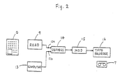
- FIG. 2 illustrates another apparatus according to the invention.
- the apparatus shown in Figure 2 can record image data on a tape T which have been produced by a reading unit 9 of a facsimile apparatus or by a personal computer 13.
- the apparatus shown in Figure 2 comprises two input terminals 12a and 12b to which the reading unit 9 and personal computer 13 can be connected respectively, a depression circuit 14, a modulating circuit 15, and a tape recording unit 16 into which a microcassetter tape T can be loaded.
- the depression circuit 14 has similar functions as those of the modulating circuit 10 in the apparatus of Figure 1, and namely includes circuitry for the MH (Modified Huffman) or MR (Modified Read) coding system to be provided with a function of data depression.
- MH Modified Huffman
- MR Modified Read
- the tape T on which image data to be reproduced are recorded can be loaded into the tape recording/reproducing unit 5 of the facsimile apparatus of Figure 1, and reproduced in the manner described in above (G).
- the output of the computer 13 is coupled to the other input terminal 12b, and the same procedures described above are performed.
- image data produced by an image processing apparatus can be recorded on a tape, and can be easily reproduced at any desired time by using a facsimile apparatus having the structure described with reference to Figure 1.
Landscapes
- Engineering & Computer Science (AREA)
- General Engineering & Computer Science (AREA)
- Multimedia (AREA)
- Signal Processing (AREA)
- Computing Systems (AREA)
- Facsimiles In General (AREA)
- Storing Facsimile Image Data (AREA)
- Signal Processing Not Specific To The Method Of Recording And Reproducing (AREA)
Abstract
Description
- The present invention relates to a facsimile apparatus capable of recording received image data on a tape and reproducing the image data recorded on the tape for printing.
- Most facsimile apparatus are provided with a semiconductor memory for temporarily storing transmitting image data or received image data.
- It is usual in personal computers, word processors or the like to record image data and/or character data in a semiconductor memory and display or print the recorded contents as necessary. If a facsimile apparatus is equipped with such a memory storing image data in addition to its original memory, prerecording may be made in that memory so that its contents can be displayed or printed as necessary, and therefore it is possible to provide a new output device to replace a printer or display used with personal computers and word processors. For example, when image data such as the operation and maintenance instructions for a facsimile apparatus is recorded in a semiconductor memory mounted in the facsimile apparatus, such advantages are offered that there is no need to separately provide an instruction manual for the facsimile apparatus and that it is not necessary to carry actual materials such as drawings, etc.
- However, with prior art facsimile apparatus, since a semiconductor memory mounted therein has a limited recording capacity and cannot be readily detached for replacement, it is only possible to output received image data and it is not possible to output image data which have been recorded by another apparatus such as a personal computer, or word processor.
- Some Japanese Laid-Open Patent Publications Nos. SHO61-198,853, SHO61-242,449, HEI1-254,065 and HEI1-270452 teach the use of a tape for recording image data which have been transmitted from another facsimile apparatus. However, the apparatus of these publications cannot record the image data read from an original on a tape, at any desired time.
- The facsimile apparatus of this invention, which overcomes the above-discussed and numerous other disadvantages and deficiencies of the prior art, comprises: a reading unit; a printing unit; and a communication unit which is to be connected between a communication line and said reading and printing units, said communication unit including modulating and demodulating means for processing image data, and said apparatus further comprises: a tape recording and reproducing unit; digital/analog converting means connected between said communication unit and said tape recording and reproducing unit; and analog/digital converting means connected between said communication unit and said tape recording and reproducing unit.
- Preferably, said communication unit may further include means for depressing image data.
- Preferably, said communication unit may further include means for expanding image data.
- The facsimile apparatus of the invention comprises: a reading unit; a printing unit; and a communication unit which is to be connected between a communication line and said reading and printing units, said communication unit including modulating and demodulating means for processing image data, and said apparatus further comprises: a tape recording and reproducing unit; digital/analog converting means connected between said communication unit and said tape recording and reproducing unit; analog/digital converting means connected between said communication unit and said tape recording and reproducing unit; and an image data input port for receiving image data from another apparatus, said image data input port coupled to said communication unit.
- Preferably, said apparatus may further comprise switching means for selectively connecting said communication unit with one of said reading unit and image data input port.
- Preferably, said communication unit may further include means for depressing image data.
- Preferably, said communication unit may further include means for expanding image data.
- The apparatus according to the invention comprises: one or more input ports for receiving image data from another apparatus; signal processing means, coupled to said input ports, for processing-image data; and a tape recording unit coupled to said signal processing means.
- Thus, the invention described herein makes possible the objectives of:
- (1) providing a facsimile apparatus which can record image data on a tape at any desired time;
- (2) providing a facsimile apparatus which can record image data produced by a reading unit, on a tape at any desired time;
- (3) providing a facsimile apparatus which can output image data at any desired time which have been produced by a reading unit and recorded on a tape;
- (4) providing a facsimile apparatus which can record image data which have been produced by another apparatus, on a tape at any desired time;
- (5) providing a facsimile apparatus which can output image data at any desired time which have been recorded by another apparatus and recorded on a tape; and
- (6) providing an apparatus which can record image data on a tape which have produced by an image processing apparatus such as a facsimile apparatus, or personal computer.
- This invention may be better understood and its numerous objects and advantages will become apparent to those skilled in the art by reference to the accompanying drawings as follows:
- Figure 1 is a block diagram illustrating a facsimile apparatus according to the invention.
- Figure 2 is a block diagram illustrating another embodiment of the invention.
- Figure 1 shows one embodiment of the invention. The
facsimile apparatus 1 shown in Figure 1 comprises amodem 2 connected to a communication line L, abuffer memory 3, a modulatingcircuit 10, ademodulating circuit 7, aprinting unit 8 connected to thedemodulating circuit 7, areading unit 9 connected to the modulatingcircuit 10 through a switch 11, and aninput terminal 12. The switch 11 has a common terminal 11a connected to the input of the modulatingcircuit 10, and terminals 11b and 11c which are connected to thereading unit 9 and theinput terminal 12, respectively. An output of anotherapparatus 13 for processing image data such as a personal computer and word processor can be coupled to theinput terminal 12. The common terminal 11a is normally connected to the terminal 11b as shown in Figure 1 so that thereading unit 9 is connected to the modulatingcircuit 10, and, when a selection key (not shown) disposed on theapparatus 1 is operated, the common terminal 11a is connected to the terminal 11c, thereby connecting thepersonal computer 13 to the modulatingcircuit 10. The modulatingcircuit 10 anddemodulating circuit 7 are coupled to thebuffer memory 3. The modulatingcircuit 10 includes circuitry for the MH (Modified Huffman) or MR (Modified Read) coding system to be provided with a function of data depression. - The
facsimile apparatus 1 further comprises, a modulatingcircuit 4, ademodulating circuit 6, and a tape recording/reproducingunit 5 which is coupled to thebuffer memory 3 through the modulatingcircuit 4 and demodulatingcircuit 6. A so-called microcassette tape or compact cassette tape T can be loaded into the tape recording/reproducingunit 5. - The
facsimile apparatus 1 having the above-described construction can perform various functions. Examples of these functions are as follows: - (A) to record image data transmitted from another facsimile apparatus;
- (B) to reproduce an image from image data transmitted from another facsimile apparatus;
- (C) to record image data of an image of an original;
- (D) to reproduce an image of an original;
- (E) to transmit image data of an image of an original to another facsimile apparatus;
- (F) to record image data which have been produced by another image processing apparatus;
- (G) to reproduce an image from image data which have been produced by another image processing apparatus; and
- (H) to transmit image data which have been produced by another image processing apparatus.
- These functions (A) - (H) of the
facsimile apparatus 1 will be described. - When receiving image data from another facsimile apparatus through the communication line L, the image data are converted by the
modem 2 to digital image signals which are then supplied to the modulatingcircuit 4 through thebuffer memory 3. In the modulatingcircuit 4, the digital image signals undergo band depression, and are converted back to analog image signals. Thereafter, the analog image signals are supplied to the tape recording/reproducingunit 5 by which the analog image signals are recorded on the tape T. In this way, image data received by thefacsimile apparatus 1 are once recorded on the tape T. Therefore, the image data transmitted from the other facsimile apparatus can be reproduced at any desired time as described below. - Image data which have been transmitted from another facsimile apparatus and recorded on the tape T in the form of analog signals (as described in above (A)) are reproduced from the tape T by the tape recording/reproducing
unit 5, and the reproduced analog signals are input to the demodulatingcircuit 6 by which the analog image signals are converted to digital signals. The digital signals are supplied via thebuffer memory 3 to thedemodulating circuit 7 by which the digital signals are expanded. The digital signals are decomposed into individual bits which are then transferred to theprinting unit 8. The image represented by the individual bits is printed on recording paper (not shown) by theprinting unit 8. - An image of an original G is read by the
reading unit 9 to be converted to digital image signals. The digital image signals are transferred to the modulatingcircuit 10 through a switch 11 in which the common contact 11a is normally connected to the contact 11b as described above. Then, the digital image signals are compressed by the modulatingcircuit 10. The compressed digital image signals are supplied to the modulatingcircuit 4 through thebuffer memory 3. In the modulatingcircuit 4, the digital image signals undergo band depression, and are converted to analog image signals. Then, the analog image signals are supplied to the tape recording/reproducingunit 5 by which the analog image signals are recorded on the tape T. - Image data which have been read from the original G by the
reading unit 9 and recorded on the tape T are reproduced from the tape T by the tape recording/reproducingunit 5. The reproduced analog signals are input to thedemodulating circuit 6 by which the analog image signals are converted to digital signals. The digital signals are supplied via thebuffer memory 3 to thedemodulating circuit 7 by which the digital signals are expanded. The digital signals are decomposed into individual bits which are then transferred to theprinting unit 8. The image represented by the individual bits is printed on recording paper by theprinting unit 8. - Image data which have been read from the original G by the
reading unit 9 and recorded on the tape T are reproduced from the tape T by the tape recording/reproducingunit 5. The reproduced analog signals are input to thedemodulating circuit 6 by which the analog image signals are converted to digital signals. The digital signals are supplied to themodem 2 through thebuffer memory 3, and converted to analog signals. The analog signals are transmitted to the destination facsimile apparatus via the communication line L. -
- The embodiment can record image data which have been produced by another image processing apparatus such as a personal computer, on the tape T. To perform this operation, an output of a
personal computer 13 in which digital image data have been produced and stored in a memory is coupled to theinput terminal 12. Then, the above-mentioned selection key (not shown) is operated so that the common terminal 11a of the switch 11 is connected to the terminal 11c coupled to theinput terminal 12. The image data are transferred as digital signals from thepersonal computer 13 to the modulatingcircuit 10 through theinput terminal 12 and switch 11. Then, the digital image signals are compressed by the modulatingcircuit 10. The compressed digital image signals are supplied to the modulatingcircuit 4 through thebuffer memory 3. In the modulatingcircuit 4, the digital image signals undergo band depression, and are converted to analog image signals. Then, the analog image signals are supplied to the tape recording/reproducingunit 5 by which the analog image signals are recorded on the tape T. After transferring the digital image data from thepersonal computer 13 to the modulatingcircuit 10, the switch 11 is returned to the normal state (i.e., common terminal 11a is connected to the terminal 11b). - Image data which have been produced by the
personal computer 13 and recorded on the tape T are reproduced from the tape T by the tape recording/reproducingunit 5. The reproduced analog signals are input to thedemodulating circuit 6 by which the analog image signals are converted to digital signals. The digital signals are supplied via thebuffer memory 3 to thedemodulating circuit 7 by which the digital signals are expanded. The digital signals are decomposed into individual bits which are then transferred to theprinting unit 8. The image represented by the individual bits is printed on recording paper by theprinting unit 8. - Image data which have been produced by the
personal computer 13 and recorded on the tape T are reproduced from the tape T by the tape recording/reproducingunit 5. The reproduced analog signals are input to thedemodulating circuit 6 by which the analog image signals are converted to digital signals. The digital signals are supplied to themodem 2 through thebuffer memory 3, and converted to analog signals. The analog signals are transmitted to the destination facsimile apparatus via the communication line L. The tape T may be the one on which image data have been recorded by the apparatus of Figure 2 (which will be described later). - In this way, the
facsimile apparatus 1 can print images which have been produced by another apparatus, on recording paper and at any desired time. If images for illustrating the manner of operating the facsimile apparatus is prerecorded on a tape, it is possible to demonstrate the operation of the apparatus while sequentially printing the images on recording paper. - Figure 2 illustrates another apparatus according to the invention. The apparatus shown in Figure 2 can record image data on a tape T which have been produced by a
reading unit 9 of a facsimile apparatus or by apersonal computer 13. The apparatus shown in Figure 2 comprises two input terminals 12a and 12b to which thereading unit 9 andpersonal computer 13 can be connected respectively, adepression circuit 14, a modulatingcircuit 15, and atape recording unit 16 into which a microcassetter tape T can be loaded. Thedepression circuit 14 has similar functions as those of the modulatingcircuit 10 in the apparatus of Figure 1, and namely includes circuitry for the MH (Modified Huffman) or MR (Modified Read) coding system to be provided with a function of data depression. - When image data of an image of an original G are to be recorded on the tape T. An image of the original G is read by the
reading unit 9 of a facsimile apparatus (or by a image scanner), and converted to digital image signals. The digital image signals are temporarily stored in a suitable memory of the facsimile apparatus. The output of the facsimile apparatus is coupled to the input terminal 12a, and thereafter the digital image signals are transferred to thedepression circuit 14 through the input terminal 12a. Then, the digital image signals are compressed by thedepression circuit 14. The compressed digital image signals are supplied to the modulatingcircuit 15. In the modulatingcircuit 15, the digital image signals are converted to analog image signals. The analog image signals are supplied to thetape recording unit 16 by which the analog image signals are recorded on the tape T. The tape T on which image data to be reproduced are recorded can be loaded into the tape recording/reproducingunit 5 of the facsimile apparatus of Figure 1, and reproduced in the manner described in above (G). When image data produced by thepersonal computer 13 are to be recorded on the tape T, the output of thecomputer 13 is coupled to the other input terminal 12b, and the same procedures described above are performed. - In this way, according to the apparatus of Figure 2, image data produced by an image processing apparatus can be recorded on a tape, and can be easily reproduced at any desired time by using a facsimile apparatus having the structure described with reference to Figure 1.
- It is understood that various other modifications will be apparent to and can be readily made by those skilled in the art without departing from the scope and spirit of this invention. Accordingly, it is not intended that the scope of the claims appended hereto be limited to the description as set forth herein, but rather that the claims be construed as encompassing all the features of patentable novelty that reside in the present invention, including all features that would be treated as equivalents thereof by those skilled in the art to which this invention pertains.
Claims (8)
- In a facsimile apparatus (1) comprising:
a reading unit (9);
a printing unit (8); and
a communication unit which is to be connected between a communication line and said reading and printing units, said communication unit including modulating (10) and demodulating means (7) for processing image data,
said apparatus further comprises:
a tape recording and reproducing unit (5);
digital/analog converting means connected between said communication unit and and said tape recording and reproducing unit; and
analog/digital converting means connected between said communication unit and said tape recording and reproducing unit. - An apparatus according to claim 1, wherein said communication unit further includes means (14) for depressing image data.
- An apparatus according to claim 2, wherein said communication unit further includes means for expanding image data.
- In a facsimile apparatus (1) comprising:
a reading unit (9);
a printing unit (8); and
a communication unit which is to be connected between a communication line and said reading and printing units, said communication unit including modulating (10) and demodulating means (7) for processing image data,
said apparatus further comprises:
a tape recording and reproducing unit (5);
digital/analog converting means (3,4) connected between said communication unit and said tape recording and reproducing unit;
analog/digital converting means (6,3) connected between said communication unit and said tape recording and reproducing unit; and
an image data input port (13) for receiving image data from another apparatus, said image data input port coupled to said communication unit. - An apparatus according to claim 4, wherein said apparatus further comprises switch means (11) for selectively connecting said communication unit with one of said reading unit and said image data input port.
- An apparatus according to claim 4, wherein said communication unit further includes means for depressing image data.
- An apparatus according to claim 6, wherein said communication unit further includes means for expanding image data.
- An apparatus comprising:
one or more input ports for receiving image data from another apparatus;
signal processing means, coupled to said input ports, for processing image data; and
a tape recording unit coupled to said signal processing means.
Applications Claiming Priority (2)
| Application Number | Priority Date | Filing Date | Title |
|---|---|---|---|
| JP4036590A JPH03242084A (en) | 1990-02-20 | 1990-02-20 | Facsimile equipment |
| JP40365/90 | 1990-02-20 |
Publications (3)
| Publication Number | Publication Date |
|---|---|
| EP0443554A2 true EP0443554A2 (en) | 1991-08-28 |
| EP0443554A3 EP0443554A3 (en) | 1992-06-10 |
| EP0443554B1 EP0443554B1 (en) | 1996-08-28 |
Family
ID=12578616
Family Applications (1)
| Application Number | Title | Priority Date | Filing Date |
|---|---|---|---|
| EP19910102467 Expired - Lifetime EP0443554B1 (en) | 1990-02-20 | 1991-02-20 | A facsimile apparatus |
Country Status (3)
| Country | Link |
|---|---|
| EP (1) | EP0443554B1 (en) |
| JP (1) | JPH03242084A (en) |
| DE (1) | DE69121603T2 (en) |
Cited By (1)
| Publication number | Priority date | Publication date | Assignee | Title |
|---|---|---|---|---|
| FR2697960A1 (en) * | 1992-11-09 | 1994-05-13 | Eurl Phonycom | Monitor-control cards for facsimile machines - has recognition, speech and memory cards taking facsimile information and passing to another machine |
Family Cites Families (5)
| Publication number | Priority date | Publication date | Assignee | Title |
|---|---|---|---|---|
| US4527193A (en) * | 1982-09-30 | 1985-07-02 | Hazeltine Corporation | Image storage system |
| US4786974A (en) * | 1984-03-26 | 1988-11-22 | Canon Kabushiki Kaisha | Image information processing system |
| JPH07118754B2 (en) * | 1987-04-15 | 1995-12-18 | キヤノン株式会社 | Image communication device |
| JPH0761113B2 (en) * | 1987-07-10 | 1995-06-28 | シャープ株式会社 | Fax machine |
| JPH01264066A (en) * | 1988-04-14 | 1989-10-20 | Fujitsu Ltd | Multiple address transmission system |
-
1990
- 1990-02-20 JP JP4036590A patent/JPH03242084A/en active Pending
-
1991
- 1991-02-20 DE DE1991621603 patent/DE69121603T2/en not_active Expired - Fee Related
- 1991-02-20 EP EP19910102467 patent/EP0443554B1/en not_active Expired - Lifetime
Cited By (1)
| Publication number | Priority date | Publication date | Assignee | Title |
|---|---|---|---|---|
| FR2697960A1 (en) * | 1992-11-09 | 1994-05-13 | Eurl Phonycom | Monitor-control cards for facsimile machines - has recognition, speech and memory cards taking facsimile information and passing to another machine |
Also Published As
| Publication number | Publication date |
|---|---|
| DE69121603D1 (en) | 1996-10-02 |
| DE69121603T2 (en) | 1997-04-03 |
| JPH03242084A (en) | 1991-10-29 |
| EP0443554A3 (en) | 1992-06-10 |
| EP0443554B1 (en) | 1996-08-28 |
Similar Documents
| Publication | Publication Date | Title |
|---|---|---|
| JPS61220559A (en) | Facsimile equipment for multiple address communication | |
| EP0443554A2 (en) | A facsimile apparatus | |
| MY123764A (en) | Information recording medium, motion-picture voice recording/reproducing apparatus, and motion-picture voice recording/reproducing method | |
| US6304920B1 (en) | Switching means for directly controlling operation of data storage devices, data storage/reproducing devices, and data reproducing devices | |
| JPH0761113B2 (en) | Fax machine | |
| JP3054220B2 (en) | Image transmission device | |
| JPS60246166A (en) | Computer facsimile connecting equipment | |
| JPS583347A (en) | Electronic mail control system | |
| JPS6376576A (en) | Data recorder | |
| JPH01141458A (en) | Facsimile equipment | |
| JP3434250B2 (en) | Digital compressed image data reproduction system and operation method thereof | |
| JPH01264471A (en) | Facsimile equipment with memory device | |
| JP2716240B2 (en) | Facsimile machine | |
| JPH01212069A (en) | Image receiving device | |
| JPH04236566A (en) | Image communication device | |
| JPS6376672A (en) | Facsimile equipment | |
| JPS636956A (en) | Video facsimile system | |
| JPH02130087A (en) | Still picture video telephone | |
| JPH02143378A (en) | Digital picture storing and reproducing device | |
| JPH05328063A (en) | Facsimile equipment | |
| JPS60229575A (en) | Facsimile equipment | |
| JPH01194651A (en) | Facsimile equipment attached with character code receiving function | |
| JPS63227173A (en) | electronic file device | |
| JPH04170856A (en) | Facsimile equipment incorporating optical disk device and document filing system | |
| JPH02151459A (en) | recording device |
Legal Events
| Date | Code | Title | Description |
|---|---|---|---|
| PUAI | Public reference made under article 153(3) epc to a published international application that has entered the european phase |
Free format text: ORIGINAL CODE: 0009012 |
|
| AK | Designated contracting states |
Kind code of ref document: A2 Designated state(s): DE GB |
|
| PUAL | Search report despatched |
Free format text: ORIGINAL CODE: 0009013 |
|
| AK | Designated contracting states |
Kind code of ref document: A3 Designated state(s): DE GB |
|
| 17P | Request for examination filed |
Effective date: 19920525 |
|
| 17Q | First examination report despatched |
Effective date: 19940315 |
|
| GRAH | Despatch of communication of intention to grant a patent |
Free format text: ORIGINAL CODE: EPIDOS IGRA |
|
| GRAH | Despatch of communication of intention to grant a patent |
Free format text: ORIGINAL CODE: EPIDOS IGRA |
|
| GRAA | (expected) grant |
Free format text: ORIGINAL CODE: 0009210 |
|
| AK | Designated contracting states |
Kind code of ref document: B1 Designated state(s): DE GB |
|
| REF | Corresponds to: |
Ref document number: 69121603 Country of ref document: DE Date of ref document: 19961002 |
|
| PLBE | No opposition filed within time limit |
Free format text: ORIGINAL CODE: 0009261 |
|
| STAA | Information on the status of an ep patent application or granted ep patent |
Free format text: STATUS: NO OPPOSITION FILED WITHIN TIME LIMIT |
|
| 26N | No opposition filed | ||
| PGFP | Annual fee paid to national office [announced via postgrant information from national office to epo] |
Ref country code: DE Payment date: 20010212 Year of fee payment: 11 |
|
| PGFP | Annual fee paid to national office [announced via postgrant information from national office to epo] |
Ref country code: GB Payment date: 20010214 Year of fee payment: 11 |
|
| REG | Reference to a national code |
Ref country code: GB Ref legal event code: IF02 |
|
| PG25 | Lapsed in a contracting state [announced via postgrant information from national office to epo] |
Ref country code: GB Free format text: LAPSE BECAUSE OF NON-PAYMENT OF DUE FEES Effective date: 20020220 |
|
| PG25 | Lapsed in a contracting state [announced via postgrant information from national office to epo] |
Ref country code: DE Free format text: LAPSE BECAUSE OF NON-PAYMENT OF DUE FEES Effective date: 20020903 |
|
| GBPC | Gb: european patent ceased through non-payment of renewal fee |
Effective date: 20020220 |