EP0443576B1 - Antrieb mindestens zweier konzentrischer Wellen zum Bewegen einer Robotor-Abtriebseinrichtung - Google Patents
Antrieb mindestens zweier konzentrischer Wellen zum Bewegen einer Robotor-Abtriebseinrichtung Download PDFInfo
- Publication number
- EP0443576B1 EP0443576B1 EP91102537A EP91102537A EP0443576B1 EP 0443576 B1 EP0443576 B1 EP 0443576B1 EP 91102537 A EP91102537 A EP 91102537A EP 91102537 A EP91102537 A EP 91102537A EP 0443576 B1 EP0443576 B1 EP 0443576B1
- Authority
- EP
- European Patent Office
- Prior art keywords
- gear
- shaft
- drive
- teeth
- toothed
- Prior art date
- Legal status (The legal status is an assumption and is not a legal conclusion. Google has not performed a legal analysis and makes no representation as to the accuracy of the status listed.)
- Expired - Lifetime
Links
Images

Classifications
-
- B—PERFORMING OPERATIONS; TRANSPORTING
- B25—HAND TOOLS; PORTABLE POWER-DRIVEN TOOLS; MANIPULATORS
- B25J—MANIPULATORS; CHAMBERS PROVIDED WITH MANIPULATION DEVICES
- B25J17/00—Joints
- B25J17/02—Wrist joints
- B25J17/0283—Three-dimensional joints
-
- B—PERFORMING OPERATIONS; TRANSPORTING
- B25—HAND TOOLS; PORTABLE POWER-DRIVEN TOOLS; MANIPULATORS
- B25J—MANIPULATORS; CHAMBERS PROVIDED WITH MANIPULATION DEVICES
- B25J17/00—Joints
- B25J17/02—Wrist joints
- B25J17/0258—Two-dimensional joints
-
- B—PERFORMING OPERATIONS; TRANSPORTING
- B25—HAND TOOLS; PORTABLE POWER-DRIVEN TOOLS; MANIPULATORS
- B25J—MANIPULATORS; CHAMBERS PROVIDED WITH MANIPULATION DEVICES
- B25J9/00—Program-controlled manipulators
- B25J9/10—Program-controlled manipulators characterised by positioning means for manipulator elements
- B25J9/102—Gears specially adapted therefor, e.g. reduction gears
Definitions
- the invention relates to a drive according to the preamble of claims 1 and 2 respectively.
- An output device of the type mentioned here is known in robots and is used to fasten devices for performing robot-typical tasks such as Gripping workpieces, welding, applying coatings such as adhesive; however, it can also be connected to a mechanism for moving a second output device, which in turn accommodates the devices mentioned above.
- the output device including the components attached to it, is moved by the robot into predetermined positions in the work space by moving its structurally predetermined translatory and / or rotary axes.
- either programmed positions can be approached or predetermined paths can be traveled.
- the structure for moving the output device is referred to as a robot gripper arm.
- Robot gripping arms of the type mentioned here are known, for example, in portal robots, but can also be used as a component of another type of robot.
- a gripping arm carried by an essentially vertically extending holder is moved by suitable drive devices in directions perpendicular to one another, for example in the direction of an x-axis and a y-axis.
- parts of the gripper arm for example a gripper, can be rotated about an axis lying in the plane mentioned, which is perpendicular to the z-axis. This axis is defined as the A axis.
- the gripper arm can rotate about the z-axis, this axis also being defined as the C-axis.
- the gripper arm is rotated about the C-axis by means of a hollow shaft carrying the gripper arm.
- a concentric shaft is provided in the interior, which enables the gripper to rotate about the A axis.
- a further concentric shaft serving to actuate a mechanism attached to the gripping arm can be provided inside the hollow shaft assigned to the A-axis. By rotating this shaft, e.g. opening and closing a gripper or actuating another robot axis.
- a drive is known in which a pinion is assigned to the A-axis, which is moved by a rack. This rotates with the C-axis and must be movable relative to the holding arm lying in the z-axis.
- the disadvantage is that the pinion must be small in order to keep the stroke of the rack within limits, so that the drive has a relatively large amount of play.
- the A axis does not intersect the C axis, rather it is offset somewhat from it so that only a limited movement of the pinion is possible.
- this drive is very space-intensive.
- An embodiment of the drive with involute toothing is particularly preferred, in which the number of teeth is compensated for by a profile shift and / or the use of different module (tooth size) of the gear pairs. In this way it is particularly easy to compensate for different center distances of gear pairs caused by a difference in the number of teeth.
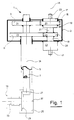
- Figure 1 shows a drive for a robot gripper arm. Only the essential parts that come into question here are shown.
- the drive 1 has a gear box 3, which includes the upper ends of two concentric shafts 5 and 7.
- both shafts are designed as hollow shafts.
- the inner shaft 7 is solid.
- the first concentric shaft 7 is also called the first shaft below
- the second concentric shaft 5 is also called the second shaft.
- a gear 9, which is also referred to as the first gear in the following, is attached to the upper end of the first shaft 7 and a gear 11, which is also referred to as the second gear, is attached to the upper end of the second shaft 5.
- the gear 15, hereinafter also referred to as the third gear is arranged on the outside of the housing 17 of the epicyclic gear 13 in a rotationally fixed manner.
- the gear 19, hereinafter also called the fourth gear, is firmly connected to the output shaft 21 of the epicyclic gear 13.
- a drive shaft 23 emerges from the housing 17 thereof, which in the exemplary embodiment shown here emerges from the gear box 3 at the top and is also referred to as an A drive.
- a lower housing 25 is provided here, which is attached to the second shaft 5.
- the first shaft 7 projects into the interior of this housing. It is provided with a first bevel gear 27 which meshes with a second bevel gear 29.
- the second bevel gear 29 is in turn attached to a flange shaft 33, which is generally perpendicular to the central axis 31 of the concentric shafts 5 and 7 and is designed here as a hollow shaft.
- a flange 35 is provided on which, for example, a gripper, not shown here, can be attached for handling workpieces.
- the robot gripper arm shown here with its associated drive can be part of a gantry robot, that is to say the robot gripper arm can be moved over a surface in the x and y directions by means of suitable drives.
- a displacement of the robot gripper arm running perpendicular to this plane, that is, in the direction of a z-axis is also conceivable.
- the central axis 31 running in the direction of this z-axis is also referred to as the C-axis, the central axis 37 of the flange shaft 33 as the A-axis.
- the output shaft 21 of the epicyclic gear 13 can continue in a second drive shaft 39, which in turn can merge into a drive shaft 41.
- the drive shaft 41 is also referred to as a C drive, since torques acting on this shaft lead to a rotation of the second drive shaft 39, the fourth gear 19 and the gear 11 at the upper end of the second shaft 5. This causes the robot gripper arm to twist about the C axis.
- a central axis 45 runs concentrically to the epicyclic gear 13, its drive shaft 23, housing 17, output shaft 21 and to the second drive shaft 39.
- the drive shaft 23 of the epicyclic gear 13 is also referred to as A-drive, because a rotation of this shaft to a rotation of the housing 17 with the third gear 15, the first gear 9, the associated first shaft 7 and finally the flange shaft 33 around Center axis 37 or around the A axis.
- the number of teeth of the gearwheels 11 and 9 attached to the upper ends of the concentric shafts 5 and 7 can be freely selected. However, the number of teeth must be the same for both gears, which, as shown, enables the decoupling of two rotary axes.
- the number of teeth of the gears 15 and 19 attached to the epicyclic gear 13 is determined by its mode of operation, that is to say whether it is a gearing or a gearing in the opposite direction. This will be discussed in more detail below.
- components for transmitting linear movements of robot axes can also interact with the third and fourth gear wheels 15 and 19.
- the decoupling of a linear movement from another linear movement is made possible by designing the first and second gear wheels 9 and 11 with an infinitely large diameter and consequently resulting in straight components such as toothed racks; these in turn are moved by the gear wheels 15, 19 of the epicyclic gearbox at defined linear speeds, for example at the same speed, which results in a decoupling effect.
- the number of teeth of at least one of the gears 15 and 19 of the epicyclic gear 13 can be multiplied by any factor, the compliance being observed whole number of teeth must be observed.
- This is also the decoupling a rotary from a translatory or a translatory from a rotary robot axis is possible, with only one of the first and second gear wheels 9 or 11 being replaced by corresponding components for transmitting the linear movements of a robot axis.
- the number of teeth of the gears 15 and 19 of the epicyclic gear 13 can be freely selected. However, the number of teeth must be the same for both gears.
- the robot gripper arm has a drive box 3 receiving a drive on the upper side of two concentric shafts 5 and 7.
- a lower housing 25 is provided, from which a flange shaft 33 with a suitable flange 35 protrudes.
- a gripper or tool attached to this flange can be driven in a suitable manner.
- electrical, hydraulic or pneumatic drives are possible, since the supply of installation lines is ensured by the hollow first shaft 7.
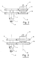
- Figures 4 and 5 which will be discussed in more detail below.
- the lower housing 25 rotates about the central axis 31 or the C axis.
- the flange 35 moves on a circular path and with it, for example, a gripper. After a rotation about the C axis, the latter can thus deposit elements picked up at any point p at a point p ', for example in the course of an automatic production line.
- Rotation around the C axis is effected by a torque acting on the C drive 41. This leads to a rotation of the fourth gear 19 and the meshing second gear 11 at the upper end of the outer second shaft 5. If a rotation of the flange shaft 33 and thus the flange 35 about the A-axis 37 is desired, a torque is applied to the A drive 23 is exerted, by means of which the third gear 15 of the epicyclic gear 13 and the gear 9 meshing with this gear are rotated at the upper end of the inner first shaft 7. A rotation of the first bevel gear 27 connected to the inner shaft also forces the second bevel gear 29 and thus the flange shaft 33 to rotate about the A axis.
- the epicyclic gear 13 shown in Figures 1 to 3 is characterized in that relative to the gear box 3 stationary drive shaft 23 and rotating housing 17 a predetermined speed difference between the output shaft 21 with gear 19 and the housing 17 with the gear 15 is given.
- gears used as epicyclic gears namely co-rotating and counter-rotating gears.
- the output rotates in the direction of rotation of the drive when the housing is held in place.
- counter-rotating gearboxes the output turns against the direction of rotation of the drive under the same conditions.
- Reduction i is the speed ratio between input and output, where i is always positive.
- Gear units with the same direction of rotation are, for example, single-stage planetary gear units in which the planet carrier serves as an output.
- Counter-rotating transmissions are, for example, cyclo or harmonic drive transmissions and single-stage planetary gear transmissions in which the ring gear serves as an output.
- the basic principle is that the speed of the output when the drive is fixed differs from that of the housing. It can be assumed that the speed of the housing 17 and thus of the associated gear 15 in the same direction is greater than that of the gear 19 on the output shaft 21. Conversely, in the case of an opposite gear, the housing 17 rotates with the associated gear 15 in the same direction and slower compared to gear 19 on output shaft 21.
- the third gear 15, here designed as a spur gear that is to say the housing 17 of the epicyclic gear 13 has rotated i entire revolutions with the drive shaft 23 standing relative to the gear box 3, the fourth gear 19 of the output shaft 21 moves in the case of a synchronous gear (i - 1) whole revolutions, with i denoting the translation of the epicyclic gear.
- the third gear wheel carries 15 x * (i-1) teeth, the fourth gear wheel 19 x * i teeth and the first and second gear wheels 9 and 11 have the same number of teeth ; 3, it is also possible to provide the third and fourth gearwheels 15 and 19 with the same number of teeth, the first gearwheel 9 with x * i and the second gearwheel 11 with x * (i-1) teeth.
- the fourth gear 19 attached to the output shaft 21 rotates (i + 1) full revolutions.
- the number of revolutions is therefore greater here.
- the third gear 15 x * (i + 1) teeth, the fourth gear 19 x * i teeth and the first and second gear 9 and 11 the same number of teeth; 3 it is also possible to provide the third and fourth gearwheels 15 and 19 with the same number of teeth, the first gearwheel 9 with x * i and the second gearwheel 11 with x * (i + 1) teeth.
- x is an arbitrary factor.
- there is a difference in the number of teeth z x.
- the number of teeth Z1, Z2, Z3 and Z4 mentioned below are primarily theoretical number of teeth, which means that they do not first have to be an integer.
- the number of teeth of each gear pair Z1, Z2 and Z3, Z4 must be multiplied by any positive factor in order to obtain integer number of teeth.
- the center distance of each wheel pair can be specifically adjusted with these factors. It is possible to use large, arbitrary, positive factors for each pair of wheels, since evenly changing both gears of a pair of gears changes its center distance, but has no influence on its translation.
- Z2 is the number of teeth of the third gear 15 on the housing 17 of the epicyclic gear 13, Z1 the number of teeth of the first gear 9 interacting with Z2, Z4 the number of teeth of the fourth gear 19 of the output shaft 21 of the epicyclic gear 13 and Z3 the number of teeth of the Z4 interacting second gear 11.
- Z1, Z2, Z3 and Z4 are at the same time the general designation of the toothed wheels with Z1, Z2, Z3 or Z4 teeth.
- the decoupling factor E is the speed ratio between the gears Z1 and Z3, which is present when the drive is stationary and the housing of the epicyclic gear is driven.
- E (Speed of gear Z1) (Speed of gear Z3)
- the number of teeth required for the decoupling can be determined using equations (1) and (2).
- Such tooth compensation can be achieved by using a suitable profile shift and / or the choice of the module of the interacting gear pairs when using involute toothing be balanced so that the same center distance of the two gear pairs is guaranteed.
- a compensation of the difference in the number of teeth z, or the initially existing different center distance of the gear pairs, can be carried out by using positive and / or negative profile shift on the gears when using involute gearing, whereby the following three possibilities result:
- At least one of the wheels of the pair of wheels with the smaller number of teeth can be designed with a positive profile shift in order to provide the center axes of the wheels of this pair of wheels with a greater distance.
- at least one of the wheels of the wheel pair with the smaller number of teeth can instead be provided with a negative profile shift in order to arrange the axes of the wheels of the wheel pair in question at a smaller distance from one another.
- the speed difference between the housing 17 and the output shaft 21 of the epicyclic gear 13 can be compensated, so that with a stationary A drive, that is, with the drive shaft 23 stationary, and with the C drive 41 driven, the first and second gear wheels 9 and 11 of the concentric shafts 7 and 5 rotate at the same speed and the desired decoupling is given.
- Z2 Z4 + z, where z is the difference in the number of teeth.
- the value of z is greater than 0 if the number of teeth Z2 of the third gear 15 is greater than the number of teeth Z4 of the fourth gear 19 and less than 0 if the number of teeth Z2 is less than the number of teeth Z4.
- the number of teeth of the decoupled drive can be calculated from these equations.
- the decoupling factor E assumes the value 1, that is to say the subordinate first shaft 7 arranged in the interior of the second shaft 5 is decoupled and rotates at the same speed when the drive shaft 23 is stationary like the driven superordinate hollow second shaft 5 surrounding the subordinate first shaft 7.
- the slower rotating third gear 15 is provided with a number of teeth larger by z than the gear 19 on the output shaft 21 of the epicyclic gear 13.
- the tooth number difference z assumes the value 1. This is usually the case when the epicyclic gearbox has a gear ratio i that is sufficiently large to enable the number of teeth to be approximately the same as i.
- the number of teeth of the gear pair Z1, Z2 - which consists of the first gear 9 and the third gear 15 - can be determined with any common factor x, the number of teeth of the gear pair Z3, Z4 - which of the second gear 11 and the fourth gear 19 exists- be multiplied by any common factor y to equalize the center distances;
- the wheel pairs Z1, Z2 and Z3, Z4 can be designed with different modules (tooth sizes).
- the number of teeth Z1 of the gear 9 of the first shaft 7 corresponds to the number of teeth Z3 of the gear 15 of the epicyclic gear 13 arranged on the housing 17.
- the number of teeth can be chosen as desired.
- the number of teeth difference z is greater than 0 if the number of teeth Z2 of the third gear 15 is less than the number of teeth Z4 of the fourth gear 19.
- the difference z is less than 0 if the number of teeth Z2 is greater than the number of teeth Z4.
- the fourth gear 19 designed as a spur gear, rotates i - 1 revolutions when the drive shaft 23 is stationary with a synchronous transmission, provided that the third gear 15 or the housing 17 of the epicyclic gear 13 is rotated i revolutions.
- the gear 11 of the second shaft 5 is driven by the associated gear 19 on the output shaft 21 of the epicyclic gear 13, that is to say by the faster of the two third and fourth gears 15 and 19 of the same size.
- the number of teeth Z3 of the second gear 11 is therefore chosen to be larger than the number of teeth Z1 of the first gear 9 by the number of teeth difference z.
- Z3 Z1 + z
- the number of teeth difference z will assume a value greater than 0 if the number of teeth Z3 is less than the number of teeth Z1, and a value less than 0 if Z3 is greater than Z1.
- gearwheel types that is to say two gearwheels with different numbers of teeth
- one type being used as the first gearwheel 9 and as the fourth gearwheel 19 and the other as the third gearwheel 15 and as the second gearwheel 11. reducing the number of different parts.
- the drive for the hollow shaft 5, the C drive does not act directly on the gear 19-1, as shown in FIGS. 1 to 3; rather, a separate drive gear ZC is provided, on which a suitable drive, which is not shown here, engages.
- a gear 9 is attached, which meshes with a gear 15-1 arranged on the housing 17-1 of the epicyclic gear 13-1.
- the hollow shaft 7 is driven via the drive shaft 23-1 of the first epicyclic gear 13-1.
- a second epicyclic gear 13-2 is provided which the gear 51 of the hollow shaft 53, which runs inside the hollow shaft 7, from the gear 9 Hollow shaft 7 decoupled.
- the gear 9 meshes with a gear 19-2 arranged on the output shaft 21-2 of the second epicyclic gear 13-2, while the gear 51 meshes with a gear 15-2 of the second epicyclic gear 13-2 fastened to the housing 17-2.
- the hollow shaft 53 is driven via the drive shaft 23-2 of the second epicyclic gear.
- a third epicyclic gear 13-3 is provided, which decouples the gear 55 of the hollow shaft 57, which runs within the hollow shaft 53, from the gear 51 of the hollow shaft 53.
- the inner and outer hollow shafts are decoupled.
- a gear 19-3 lying on the output shaft 21-3 of the third epicyclic gear 13-3 meshes with the gear 51 of the hollow shaft 53.
- a gear 15-3 rotating with the housing 17-3 of the epicyclic gear 13-3 meshes with the gear 55 innermost shaft 57.
- the shaft 57 is driven by the drive shaft 23-3 of the third epicyclic gear 13-3.
- the installation position of the epicyclic gears can be freely selected; if, for example, the tooth geometries of the gears 9 and 11 are identical, it is irrelevant whether gear 15-1 cooperates with 9 and 19-1 with 11 or gear 15-1 with 11 and 19-1 with 9.
- the hollow shaft 5 serving there as the basic shaft can be subjected to a rotation by applying a torque to the drive shaft 41, the C drive.
- a torque to the drive shaft 41, the C drive.
- an additional targeted rotation of the hollow shaft 33 around the can by a targeted torque on the A-drive 23 A-axis take place without there being an impairment of the rotation about the C-axis.
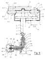
- FIG. 5 shows a further exemplary embodiment of a robot gripper arm which is very similar to that shown in FIG. 1.
- the same reference numerals are therefore used for parts that match in both figures. Their description is omitted here; in this regard, reference is made to the explanations for FIG. 1.
- the robot gripping arm according to FIG. 5 is characterized by an additional shaft 53 running inside the two hollow shafts 5 and 7, which is provided with a gear 51 at its upper end.
- a second epicyclic gear 13-2 is provided between the gear 9 of the hollow shaft 7 enclosing the shaft 53 and the gear 51 of the shaft 53 designed here as a hollow shaft.
- On its housing 17-2 a gear 15-2 is rotatably arranged, which meshes with the gear 9.
- the output shaft 21-2 of the second gear carries a fixed gear 19-2 which meshes with the gear 51.
- the drive shaft 23-2 of the second transmission gear 13-2 protrudes from the housing 17-2 on the side opposite the output shaft 21-2. It can be seen from the illustration in FIG. 5 that the second reduction gear 13-2 is arranged in the opposite direction to the first gear 13, that is to say that the output shaft 21-2 is arranged here above the housing 17-2.
- a first bevel gear with bevel gears 27 and 29 is accommodated, which cooperates with the hollow shaft 7 and the hollow shaft 33 which is concentric with the A-axis 37.
- the hollow shaft 7 rotates about the C axis 31
- the hollow shaft 33 is rotated about the A axis 37.
- a further bevel gear transmission is provided, which has a first bevel gear 127, which is assigned to the shaft 53.
- a second bevel gear 129 is assigned to a shaft 133 arranged concentrically with the hollow shaft 33.
- a gripper arrangement 135 is provided which is opened and closed by rotation of the shaft 133. This rotation causes, for example, an axial displacement of an internal threaded piece 139 held in a rotationally fixed manner relative to the shaft 33 on the external thread 137 of the shaft 133.
- this displacement of the internal thread piece 139 leads to the opening or closing of the gripping arms 141, which are attached to a flange 35 the hollow shaft 33 are pivotally mounted about a pivot pin 143 and simultaneously engage in two longitudinal grooves of the internal threaded piece 139.
- the transmission ratio of the bevel gears 127 and 129 for driving the gripper 135 has the value 1. That is, when the bevel gear 127 makes two revolutions, the shaft 133 also rotates twice. If the shaft 33 rotating about the A axis is to make one revolution, then the shaft 133 must also rotate one revolution if the gripper 135 is not to change its position during the rotation of the shaft 33.
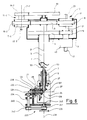
- FIG. 6 shows a further exemplary embodiment of a gripper arm similar to FIG. 1 with an additional B-axis arrangement 220, the axis 238 of which is arranged perpendicular to the A-axis 37 and can be pivoted about the latter.
- the flange 235 is the robot output device on which a device such as e.g. a gripper can be attached. This is not shown here.
- FIG. 6 in comparison to FIG. 5, a B-axis arrangement 220 is attached to the hollow shaft 33 instead of a gripper arrangement; 6, the shaft 133 is now used to drive the flange 235 on the B-axis housing 236.
- the rotary movement of shaft 133 is transmitted in FIG. 6 via the bevel gear pair 230, 231 to a further shaft 234, which in the B-axis Housing 236 is mounted and at the end of a toothed belt pulley 240 is attached.
- the Fixed flange 235 On the shaft 245 is the Fixed flange 235, which is rotatably mounted about the B axis 238 and is used for attaching a gripper, for example.
- the kinematics of the structure driven by a decoupling gear can be taken into account by the decoupling factor, whereby the number of teeth of the gear wheels of the drive, i.e. the gear wheels of the shafts and the associated epicyclic gear, can be adapted to various decoupling factors using the given equations.
Landscapes
- Engineering & Computer Science (AREA)
- Robotics (AREA)
- Mechanical Engineering (AREA)
- Retarders (AREA)
- Manipulator (AREA)
Applications Claiming Priority (2)
| Application Number | Priority Date | Filing Date | Title |
|---|---|---|---|
| DE4005765 | 1990-02-23 | ||
| DE4005765 | 1990-02-23 |
Publications (2)
| Publication Number | Publication Date |
|---|---|
| EP0443576A1 EP0443576A1 (de) | 1991-08-28 |
| EP0443576B1 true EP0443576B1 (de) | 1994-05-04 |
Family
ID=6400838
Family Applications (1)
| Application Number | Title | Priority Date | Filing Date |
|---|---|---|---|
| EP91102537A Expired - Lifetime EP0443576B1 (de) | 1990-02-23 | 1991-02-21 | Antrieb mindestens zweier konzentrischer Wellen zum Bewegen einer Robotor-Abtriebseinrichtung |
Country Status (5)
| Country | Link |
|---|---|
| EP (1) | EP0443576B1 (da) |
| AT (1) | ATE105224T1 (da) |
| DE (2) | DE59101525D1 (da) |
| DK (1) | DK0443576T3 (da) |
| ES (1) | ES2052292T3 (da) |
Cited By (3)
| Publication number | Priority date | Publication date | Assignee | Title |
|---|---|---|---|---|
| EP2514573A1 (en) * | 2011-04-19 | 2012-10-24 | Kabushiki Kaisha Yaskawa Denki | Robot |
| EP2514574A1 (en) * | 2011-04-19 | 2012-10-24 | Kabushiki Kaisha Yaskawa Denki | Robot |
| US11691270B2 (en) * | 2019-07-31 | 2023-07-04 | Sanctuary Cognitive Systems Corporation | Mechanism with three degrees-of-freedom (DOF) output to provide independent control over roll, pitch, and yaw of output structure |
Families Citing this family (19)
| Publication number | Priority date | Publication date | Assignee | Title |
|---|---|---|---|---|
| JP2511894Y2 (ja) * | 1991-09-30 | 1996-09-25 | 川崎重工業株式会社 | 産業用ロボット |
| DE4428488C1 (de) * | 1994-08-12 | 1995-10-26 | Hans Richter | Handgelenk für die Arbeitshand eines Roboters |
| JPH106270A (ja) * | 1996-06-24 | 1998-01-13 | Fanuc Ltd | 産業用ロボット |
| DE19855478B4 (de) * | 1998-12-01 | 2006-01-12 | Steinbichler Optotechnik Gmbh | Verfahren und Vorrichtung zur optischen Erfassung einer Kontrastlinie |
| US6263755B1 (en) * | 1999-02-10 | 2001-07-24 | New York University | Robotic manipulator and method |
| FR2853273B1 (fr) * | 2003-04-04 | 2006-03-10 | Commissariat Energie Atomique | Dispositif d'actionnement, notamment pour un bras articule |
| WO2010013234A1 (en) * | 2008-07-28 | 2010-02-04 | Mordehai Sholev | Variable axial-angle coupling |
| US10220522B2 (en) | 2013-12-12 | 2019-03-05 | Covidien Lp | Gear train assemblies for robotic surgical systems |
| EP3463157A4 (en) | 2016-05-26 | 2020-01-22 | Covidien LP | ROBOTIC SURGICAL ARRANGEMENTS |
| JP2020533061A (ja) | 2017-09-06 | 2020-11-19 | コヴィディエン リミテッド パートナーシップ | 手術ロボットの境界スケーリング |
| AU2018330433A1 (en) | 2017-09-08 | 2020-03-19 | Covidien Lp | Energy disconnect for robotic surgical assemblies |
| US12193774B2 (en) | 2018-01-09 | 2025-01-14 | Covidien Lp | Sterile interface module for robotic surgical assemblies |
| CN117243697A (zh) | 2018-01-10 | 2023-12-19 | 柯惠Lp公司 | 机器人手术组件及其接合器组件 |
| CA3090551A1 (en) | 2018-03-29 | 2019-10-03 | Covidien Lp | Robotic surgical systems and instrument drive assemblies |
| CN108608447A (zh) * | 2018-05-02 | 2018-10-02 | 阜阳盛东智能制造技术研发有限公司 | 一种用于上料机械手的连接机构 |
| US12029507B2 (en) | 2018-07-26 | 2024-07-09 | Covidien Lp | Surgical robotic systems |
| CN109253232A (zh) * | 2018-09-21 | 2019-01-22 | 上海飞珀机器人科技有限公司 | 一种双自由度齿轮箱模组 |
| CN112114539B (zh) * | 2020-09-25 | 2023-11-28 | 成都易慧家科技有限公司 | 一种双电机驱动推拉门窗的控制系统及其方法 |
| EP4325086A1 (en) * | 2022-08-18 | 2024-02-21 | Volvo Truck Corporation | A transmission for a vehicle |
Family Cites Families (6)
| Publication number | Priority date | Publication date | Assignee | Title |
|---|---|---|---|---|
| JPS4921672Y1 (da) * | 1970-08-21 | 1974-06-10 | ||
| US3971266A (en) * | 1973-07-17 | 1976-07-27 | Nippondenso Co., Ltd. | Power transmission device |
| US3922930A (en) * | 1974-12-23 | 1975-12-02 | Nasa | Remotely operable articulated manipulator |
| SU763082A1 (ru) * | 1977-07-01 | 1980-09-15 | Предприятие П/Я Р-6930 | Манипул тор модульного типа |
| DE3626610A1 (de) * | 1986-08-06 | 1988-02-18 | Fibro Gmbh | Portalsystem |
| FR2620837B1 (fr) * | 1987-09-21 | 1990-11-30 | Commissariat Energie Atomique | Dispositif d'orientation d'un objet autour de deux axes de rotation |
-
1991
- 1991-02-21 DE DE59101525T patent/DE59101525D1/de not_active Expired - Fee Related
- 1991-02-21 AT AT9191102537T patent/ATE105224T1/de not_active IP Right Cessation
- 1991-02-21 EP EP91102537A patent/EP0443576B1/de not_active Expired - Lifetime
- 1991-02-21 DE DE4105483A patent/DE4105483A1/de not_active Withdrawn
- 1991-02-21 DK DK91102537.7T patent/DK0443576T3/da active
- 1991-02-21 ES ES91102537T patent/ES2052292T3/es not_active Expired - Lifetime
Cited By (6)
| Publication number | Priority date | Publication date | Assignee | Title |
|---|---|---|---|---|
| EP2514573A1 (en) * | 2011-04-19 | 2012-10-24 | Kabushiki Kaisha Yaskawa Denki | Robot |
| EP2514574A1 (en) * | 2011-04-19 | 2012-10-24 | Kabushiki Kaisha Yaskawa Denki | Robot |
| CN102744730A (zh) * | 2011-04-19 | 2012-10-24 | 株式会社安川电机 | 机器人 |
| CN102744730B (zh) * | 2011-04-19 | 2015-05-20 | 株式会社安川电机 | 机器人 |
| US9095982B2 (en) | 2011-04-19 | 2015-08-04 | Kabushiki Kaisha Yaskawa Denki | Drive apparatus and robot |
| US11691270B2 (en) * | 2019-07-31 | 2023-07-04 | Sanctuary Cognitive Systems Corporation | Mechanism with three degrees-of-freedom (DOF) output to provide independent control over roll, pitch, and yaw of output structure |
Also Published As
| Publication number | Publication date |
|---|---|
| ES2052292T3 (es) | 1994-07-01 |
| DK0443576T3 (da) | 1994-09-19 |
| EP0443576A1 (de) | 1991-08-28 |
| DE59101525D1 (de) | 1994-06-09 |
| ATE105224T1 (de) | 1994-05-15 |
| DE4105483A1 (de) | 1991-08-29 |
Similar Documents
| Publication | Publication Date | Title |
|---|---|---|
| EP0443576B1 (de) | Antrieb mindestens zweier konzentrischer Wellen zum Bewegen einer Robotor-Abtriebseinrichtung | |
| DE2751579C2 (de) | Motorgetriebener Manipulator | |
| DE3525806C2 (da) | ||
| DE3722643C1 (de) | Werkzeugrevolver | |
| DE2619336B2 (de) | Gelenkkopf für einen Manipulator zur Befestigung an einem Manipulatorann | |
| EP0674122A2 (de) | Getriebemotor | |
| EP0101569B1 (de) | Vorrichtung zum Antrieb der beiden Achsen des Handgliedes eines Industrieroboters | |
| WO2020058238A1 (de) | Getriebevorrichtung mit einem planetengetriebe und einem differentialgetriebe sowie antriebsvorrichtung zum elektrischen antrieb eines kraftfahrzeugs | |
| WO2003044394A1 (de) | Einrichtung zur erzeugung einer drehbewegung einer welle | |
| WO2022111959A1 (de) | Vorrichtung zur automatisierten herstellung von schraubverbindungen | |
| EP0580958B1 (de) | Vorrichtung zum Entnehmen, Transportieren, Aufrichten und Einsetzen von Faltschachteln | |
| EP0403693B1 (de) | Vorrichtung zum Erzeugen eines Stelldrehmomentes für ein Bewegungswandlungssystem, insbesondere zum Verstellen der Backen eines Futters oder der von ihnen ausgeübten Spannkraft | |
| EP0543196B1 (de) | Antriebsanordnung für Deckel-Gummiermaschinen | |
| DE102020212680A1 (de) | Positioniereinrichtung | |
| EP1091826B1 (de) | Werkzeuganordnung für rotierend angetriebene werkzeuge | |
| EP0782899A1 (de) | Werkzeugmaschine | |
| DE102006061463A1 (de) | Vorrichtung zum variablen Antreiben einer Hohlwelle mit einer innenliegenden Spindel | |
| EP2532459B1 (de) | Verfahren zum Betreiben einer Werkzeugmaschine | |
| DE1500354C3 (da) | ||
| EP3750674B1 (de) | Roboterarm sowie verfahren zu seiner steuerung | |
| DE202012007342U1 (de) | Schaltgetriebe, das zwischen mindestens drei Schaltstufen umschaltbar ist | |
| EP0183737B1 (de) | Vorrichtung zum herstellen von werkstücken mit polygoner aussen- und/oder innenform | |
| EP0202415A2 (de) | Antriebsvorrichtung zur Erzeugung von Schwenkbewegungen und weiteren Bewegungen | |
| DE102019113372B4 (de) | Roboterarm sowie Verfahren zu seiner Steuerung | |
| DE102005042718A1 (de) | Werkzeug zur spanenden Bearbeitung von Werkstückoberflächen |
Legal Events
| Date | Code | Title | Description |
|---|---|---|---|
| PUAI | Public reference made under article 153(3) epc to a published international application that has entered the european phase |
Free format text: ORIGINAL CODE: 0009012 |
|
| AK | Designated contracting states |
Kind code of ref document: A1 Designated state(s): AT BE CH DE DK ES FR GB GR IT LI LU NL SE |
|
| 17P | Request for examination filed |
Effective date: 19920213 |
|
| 17Q | First examination report despatched |
Effective date: 19930129 |
|
| GRAA | (expected) grant |
Free format text: ORIGINAL CODE: 0009210 |
|
| RAP3 | Party data changed (applicant data changed or rights of an application transferred) |
Owner name: KERPE, STEFAN |
|
| AK | Designated contracting states |
Kind code of ref document: B1 Designated state(s): AT BE CH DE DK ES FR GB GR IT LI LU NL SE |
|
| REF | Corresponds to: |
Ref document number: 105224 Country of ref document: AT Date of ref document: 19940515 Kind code of ref document: T |
|
| ITF | It: translation for a ep patent filed | ||
| REF | Corresponds to: |
Ref document number: 59101525 Country of ref document: DE Date of ref document: 19940609 |
|
| REG | Reference to a national code |
Ref country code: ES Ref legal event code: FG2A Ref document number: 2052292 Country of ref document: ES Kind code of ref document: T3 |
|
| GBT | Gb: translation of ep patent filed (gb section 77(6)(a)/1977) |
Effective date: 19940623 |
|
| ET | Fr: translation filed | ||
| REG | Reference to a national code |
Ref country code: DK Ref legal event code: T3 |
|
| REG | Reference to a national code |
Ref country code: GR Ref legal event code: FG4A Free format text: 3012793 |
|
| EAL | Se: european patent in force in sweden |
Ref document number: 91102537.7 |
|
| PLBE | No opposition filed within time limit |
Free format text: ORIGINAL CODE: 0009261 |
|
| STAA | Information on the status of an ep patent application or granted ep patent |
Free format text: STATUS: NO OPPOSITION FILED WITHIN TIME LIMIT |
|
| 26N | No opposition filed | ||
| REG | Reference to a national code |
Ref country code: GB Ref legal event code: IF02 |
|
| PGFP | Annual fee paid to national office [announced via postgrant information from national office to epo] |
Ref country code: DK Payment date: 20050114 Year of fee payment: 15 |
|
| PGFP | Annual fee paid to national office [announced via postgrant information from national office to epo] |
Ref country code: GB Payment date: 20050118 Year of fee payment: 15 |
|
| PGFP | Annual fee paid to national office [announced via postgrant information from national office to epo] |
Ref country code: NL Payment date: 20050119 Year of fee payment: 15 |
|
| PGFP | Annual fee paid to national office [announced via postgrant information from national office to epo] |
Ref country code: GR Payment date: 20050126 Year of fee payment: 15 |
|
| PGFP | Annual fee paid to national office [announced via postgrant information from national office to epo] |
Ref country code: LU Payment date: 20050208 Year of fee payment: 15 |
|
| PGFP | Annual fee paid to national office [announced via postgrant information from national office to epo] |
Ref country code: BE Payment date: 20050221 Year of fee payment: 15 |
|
| PG25 | Lapsed in a contracting state [announced via postgrant information from national office to epo] |
Ref country code: GB Free format text: LAPSE BECAUSE OF NON-PAYMENT OF DUE FEES Effective date: 20060221 |
|
| PG25 | Lapsed in a contracting state [announced via postgrant information from national office to epo] |
Ref country code: BE Free format text: LAPSE BECAUSE OF NON-PAYMENT OF DUE FEES Effective date: 20060228 Ref country code: DK Free format text: LAPSE BECAUSE OF NON-PAYMENT OF DUE FEES Effective date: 20060228 Ref country code: LU Free format text: LAPSE BECAUSE OF NON-PAYMENT OF DUE FEES Effective date: 20060228 |
|
| PG25 | Lapsed in a contracting state [announced via postgrant information from national office to epo] |
Ref country code: NL Free format text: LAPSE BECAUSE OF NON-PAYMENT OF DUE FEES Effective date: 20060901 |
|
| REG | Reference to a national code |
Ref country code: DK Ref legal event code: EBP |
|
| GBPC | Gb: european patent ceased through non-payment of renewal fee |
Effective date: 20060221 |
|
| NLV4 | Nl: lapsed or anulled due to non-payment of the annual fee |
Effective date: 20060901 |
|
| BERE | Be: lapsed |
Owner name: *KERPE STEFAN Effective date: 20060228 |
|
| PGFP | Annual fee paid to national office [announced via postgrant information from national office to epo] |
Ref country code: CH Payment date: 20080225 Year of fee payment: 18 Ref country code: ES Payment date: 20080221 Year of fee payment: 18 |
|
| PGFP | Annual fee paid to national office [announced via postgrant information from national office to epo] |
Ref country code: IT Payment date: 20080227 Year of fee payment: 18 Ref country code: SE Payment date: 20080225 Year of fee payment: 18 |
|
| PGFP | Annual fee paid to national office [announced via postgrant information from national office to epo] |
Ref country code: AT Payment date: 20080222 Year of fee payment: 18 |
|
| PGFP | Annual fee paid to national office [announced via postgrant information from national office to epo] |
Ref country code: DE Payment date: 20080424 Year of fee payment: 18 Ref country code: FR Payment date: 20080219 Year of fee payment: 18 |
|
| PG25 | Lapsed in a contracting state [announced via postgrant information from national office to epo] |
Ref country code: GR Free format text: LAPSE BECAUSE OF NON-PAYMENT OF DUE FEES Effective date: 20060904 |
|
| REG | Reference to a national code |
Ref country code: CH Ref legal event code: PL |
|
| EUG | Se: european patent has lapsed | ||
| PG25 | Lapsed in a contracting state [announced via postgrant information from national office to epo] |
Ref country code: LI Free format text: LAPSE BECAUSE OF NON-PAYMENT OF DUE FEES Effective date: 20090228 Ref country code: CH Free format text: LAPSE BECAUSE OF NON-PAYMENT OF DUE FEES Effective date: 20090228 Ref country code: AT Free format text: LAPSE BECAUSE OF NON-PAYMENT OF DUE FEES Effective date: 20090221 |
|
| REG | Reference to a national code |
Ref country code: FR Ref legal event code: ST Effective date: 20091030 |
|
| PG25 | Lapsed in a contracting state [announced via postgrant information from national office to epo] |
Ref country code: DE Free format text: LAPSE BECAUSE OF NON-PAYMENT OF DUE FEES Effective date: 20090901 |
|
| REG | Reference to a national code |
Ref country code: ES Ref legal event code: FD2A Effective date: 20090223 |
|
| PG25 | Lapsed in a contracting state [announced via postgrant information from national office to epo] |
Ref country code: FR Free format text: LAPSE BECAUSE OF NON-PAYMENT OF DUE FEES Effective date: 20090302 |
|
| PG25 | Lapsed in a contracting state [announced via postgrant information from national office to epo] |
Ref country code: ES Free format text: LAPSE BECAUSE OF NON-PAYMENT OF DUE FEES Effective date: 20090223 |
|
| PG25 | Lapsed in a contracting state [announced via postgrant information from national office to epo] |
Ref country code: IT Free format text: LAPSE BECAUSE OF NON-PAYMENT OF DUE FEES Effective date: 20090221 |
|
| PG25 | Lapsed in a contracting state [announced via postgrant information from national office to epo] |
Ref country code: SE Free format text: LAPSE BECAUSE OF NON-PAYMENT OF DUE FEES Effective date: 20090222 |