EP0443662A2 - Système de fixation pour bras de pulvÀ©risation rotatif dans un lave-vaisselle - Google Patents
Système de fixation pour bras de pulvÀ©risation rotatif dans un lave-vaisselle Download PDFInfo
- Publication number
- EP0443662A2 EP0443662A2 EP91200285A EP91200285A EP0443662A2 EP 0443662 A2 EP0443662 A2 EP 0443662A2 EP 91200285 A EP91200285 A EP 91200285A EP 91200285 A EP91200285 A EP 91200285A EP 0443662 A2 EP0443662 A2 EP 0443662A2
- Authority
- EP
- European Patent Office
- Prior art keywords
- sealing ring
- support tube
- rotor
- cylinder part
- spray arm
- Prior art date
- Legal status (The legal status is an assumption and is not a legal conclusion. Google has not performed a legal analysis and makes no representation as to the accuracy of the status listed.)
- Granted
Links
- 239000007921 spray Substances 0.000 title claims abstract description 16
- 238000007789 sealing Methods 0.000 claims abstract description 79
- XLYOFNOQVPJJNP-UHFFFAOYSA-N water Substances O XLYOFNOQVPJJNP-UHFFFAOYSA-N 0.000 claims abstract description 15
- 238000010276 construction Methods 0.000 claims description 4
- 238000011010 flushing procedure Methods 0.000 claims description 3
- 238000004851 dishwashing Methods 0.000 abstract 1
- 239000008237 rinsing water Substances 0.000 description 2
- 238000005406 washing Methods 0.000 description 2
- 230000007423 decrease Effects 0.000 description 1
- 238000006073 displacement reaction Methods 0.000 description 1
- 229920002457 flexible plastic Polymers 0.000 description 1
- 238000003780 insertion Methods 0.000 description 1
- 230000037431 insertion Effects 0.000 description 1
- 238000005461 lubrication Methods 0.000 description 1
- 238000000034 method Methods 0.000 description 1
- 230000000149 penetrating effect Effects 0.000 description 1
Images

Classifications
-
- A—HUMAN NECESSITIES
- A47—FURNITURE; DOMESTIC ARTICLES OR APPLIANCES; COFFEE MILLS; SPICE MILLS; SUCTION CLEANERS IN GENERAL
- A47L—DOMESTIC WASHING OR CLEANING; SUCTION CLEANERS IN GENERAL
- A47L15/00—Washing or rinsing machines for crockery or tableware
- A47L15/14—Washing or rinsing machines for crockery or tableware with stationary crockery baskets and spraying devices within the cleaning chamber
- A47L15/18—Washing or rinsing machines for crockery or tableware with stationary crockery baskets and spraying devices within the cleaning chamber with movably-mounted spraying devices
- A47L15/22—Rotary spraying devices
- A47L15/23—Rotary spraying devices moved by means of the sprays
Definitions
- the invention relates to a spray arm mounting in a dishwasher with a stationary support tube for the supply of washing water, a rotor rotatably mounted on the support tube for distributing the washing water and with a sealing ring that seals a gap between the rotor and the support tube and that is rotationally fixed with a lateral surface abuts on a cylinder part of the rotor and with an end face on a sealing surface of the support tube lying parallel to the rotor plane.
- Such a design is such.
- B. become known from DE-PS 34 30 464.
- the rotor is rotatably mounted on a bearing journal which is fixedly connected to the support tube.
- the rotor plugged onto the trunnion is held by a nut screwed onto the free end of the trunnion, with play remaining between the nut and the top of the rotor, so that the rotor is rotatably supported on the trunnion and thus on the support tube.
- the cylinder part of the rotor surrounds the free end of the support tube to form a gap.
- a radially resilient slotted sealing ring lies with its outer lateral surface in a rotationally fixed manner on the inner lateral surface of the cylinder part and runs around in a sealing groove of the support tube.
- one or the other end face of the sealing ring on the associated partial surface of the sealing groove apply and thus forms a seal. If there is wear in the sealing areas, the sealing ring is automatically readjusted.
- the rotor is also rotatably mounted on a bearing journal connected to the support tube via a special bearing bush. With this type of construction too, the rotor is secured against loosening by a nut screwed onto the free end of the bearing journal.
- the inner cylinder part of the rotor is surrounded by the support tube to form a gap, a sealing ring being provided in the gap, which sits with its inner circumferential surface on the outer circumferential surface of the cylinder part and with its one end face a sealing surface with a union nut of the support tube.
- the invention has for its object to simplify and improve a spray arm mounting of the type mentioned in terms of its structure and assembly.
- This object is achieved according to the invention in that the rotor, for. B. via a blind hole and a bearing pin, is placed on the support tube, that the sealing ring is fixed in the axial direction of the rotor fixed to the cylinder part and that the rotor is secured by an attack on the sealing ring counter bearing of the support tube against loosening.
- the sealing ring takes over both the function of the seal and the function of the holder of the rotor
- a particularly simple and secure fastening of the sealing ring against axial displacements results from the fact that it is mounted in a circumferential annular groove of the cylinder part. This enables a particularly simple assembly of the sealing ring by snapping into the ring groove if the sealing ring is designed to be radially flexible and either slotted or closed.
- the rotationally fixed mounting of the sealing ring on the cylinder part generally prevents relative movement and thus wear between these two parts.
- a driver engaging in a clearance of the sealing ring can be provided.
- a relative and rotational movement between the rotor and the sealing ring is thus avoided in a simple and reliable manner, so that the cylinder part or the rotor remain wear-free. It is essential in the invention thus that in the normal case only axial sliding friction takes place between an end face of the sealing ring and part of the support tube, the support tube simultaneously forming the counter bearing with the holding function mentioned above.
- the sealing ring can be provided with bores running in the axial direction.
- a union nut which is screwed onto the free end of the support tube is preferably provided as a counter-bearing for the sealing ring fastened to the outer circumferential surface of the cylinder part, the end face of the sealing ring remote from the sealing surface being pressurized by the flushing water.
- the thread of the union nut and the support tube is replaced by a bayonet lock, the direction of rotation of the rotor can be set as desired without fear of loosening the union nut. This also makes assembly easier.
- a radially outwardly projecting, circumferential flange is provided at the end of the support tube as a counterbearing for the sealing ring fastened to the inner circumferential surface of the cylinder part Sealing ring forms.
- Both types enable simple assembly and require fewer components than the known types according to the prior art and prevent the passage of peeling water in the axle bearing area of the rotor.
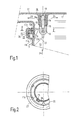
- FIG. 1 and 2 shows a support tube 10 fixedly attached to a dishwasher with an outer ring 11 and a centrally arranged bearing part 12 which is connected to the outer ring 11 via flanges 13.
- a bearing journal 14 is firmly injected into the bearing part 12, onto which a bearing bush 15 is placed.
- 16 with a rotor is designated, which has a centrally arranged hub 16a and two spray arms 17.
- the rotor 16 is through a blind hole drilled in the hub 16a 18 placed on the bearing pin 14 or the bearing bush 15.
- a cylinder part 19 attached to the lower end of the rotor 16 is surrounded by the outer ring 11 of the support tube 10, forming a gap 20.
- the cylinder part 19 has a circumferential annular groove 21, in which a radially resilient, slotted sealing ring 22 (piston ring) is embedded.
- the sealing ring 22 sits with its inner lateral surface 22a firmly on the bottom of the groove 21 of the cylinder part 19.
- a union nut 23 is screwed onto the outer end 11a of the outer ring 11 and forms a seal with an end face 23a with the end face 22b of the sealing ring.
- the union nut 23 also forms the counterbearing for the sealing ring 22 when the rotor 16 is pressed against the end face 23a of the union nut over the end face 22b of the sealing ring 22 when the rinsing water flows in in the direction 24. This prevents the rotor 16 from being detached from the support tube 10.
- a protruding driver 25 is provided in the groove 21, which engages in a recess 26 in the sealing ring 22.
- the assembly is carried out in a simple manner such that the rotor 16 is first provided with the bearing bush 15. Then the union nut 23 is pushed over the cylinder part 19 and the sealing ring 22 is embedded in the groove 21. Then this assembled unit comprising the rotor 16, the union nut 23 and the sealing ring 22 is pushed onto the bearing pin 14 of the rotor 16 via the blind hole 19 and then by means of the union nut 23 the ring part 11a screwed on. With 11b ribs for guiding the rinse water are designated.
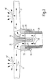
- the cylinder part 27 includes the support tube 29 to form a gap 28, the annular groove 30 for receiving and fastening the sealing ring 31 now being arranged on the inside of the cylinder part 27.
- the sealing ring 31 rotates in an annular sealing groove 32 in the support tube 29.
- the sealing groove 32 is delimited at the upper end by a radially outwardly projecting ring flange 33.
- This ring flange 33 forms a seal on the one hand with the end face of the sealing ring 31 facing it and, on the other hand, the counter bearing for the sealing ring 31 when the latter, together with the rotor 16, is pressed upward with the flushing water flowing in.
- the sealing ring 31 also assumes both a sealing and a holding function. Especially when the rinsing water flows in, the rotor 16 is pressed upward, whereby a loosening from the support tube 29 by the holding and sealing ring 31 is prevented. In the further course of operation, the pressure in the rotor 16 drops because water emerges from the spray openings 16 '. Since water penetrating through the gap 28 acts simultaneously on the sealing ring 31, the rotor 16 is now pressed down. In this case, there is a seal between the lower end face of the sealing ring 31 and the facing surface of the sealing groove 32.
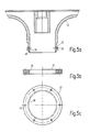
- FIG. 4a shows the cylindrical end 19 according to FIG. 1 with the annular groove 21 into which the sealing ring 34 according to FIG. 4b is to be introduced.
- the inner diameter of the sealing ring 34 is somewhat smaller than the diameter of the annular groove 21 on the groove base.
- the sealing ring 34 is pushed onto the cylinder part 19 until it snaps into the annular groove 21. This is possible because both parts are made of flexible plastic. After the process, the sealing ring 34 is firmly attached to the rotor with a press fit.
- the end of the cylinder part 19 is chamfered for insertion.
- FIGS. 5a again shows the cylinder part 19, the beveled parts of which are designed here as locking elements 36 resilient in the direction of the arrow 35.
- the sealing ring 37 shown in FIGS. 5b and c When the sealing ring 37 shown in FIGS. 5b and c is applied, the latching elements 36 yield to the inside and then snap back, so that the sealing ring 37 is clamped in place. Slipping is prevented by circumferential teeth 38 on the inner circumferential surface of the sealing ring 37. With 39 through holes in the sealing ring 37 are designated.
Landscapes
- Washing And Drying Of Tableware (AREA)
Applications Claiming Priority (2)
| Application Number | Priority Date | Filing Date | Title |
|---|---|---|---|
| DE4004319 | 1990-02-13 | ||
| DE4004319A DE4004319A1 (de) | 1990-02-13 | 1990-02-13 | Sprueharmlagerung bei einer geschirrspuelmaschine |
Publications (3)
| Publication Number | Publication Date |
|---|---|
| EP0443662A2 true EP0443662A2 (fr) | 1991-08-28 |
| EP0443662A3 EP0443662A3 (en) | 1991-10-09 |
| EP0443662B1 EP0443662B1 (fr) | 1995-01-04 |
Family
ID=6399998
Family Applications (1)
| Application Number | Title | Priority Date | Filing Date |
|---|---|---|---|
| EP91200285A Expired - Lifetime EP0443662B1 (fr) | 1990-02-13 | 1991-02-11 | Système de fixation pour bras de pulvérisation rotatif dans un lave-vaisselle |
Country Status (2)
| Country | Link |
|---|---|
| EP (1) | EP0443662B1 (fr) |
| DE (2) | DE4004319A1 (fr) |
Cited By (6)
| Publication number | Priority date | Publication date | Assignee | Title |
|---|---|---|---|---|
| EP1634527A3 (fr) * | 2004-09-14 | 2010-02-17 | Premark FEG L.L.C. | Ensemble de montage d'un bras d'arrosage pour lave-vaisselle |
| EP2721989A1 (fr) * | 2012-10-18 | 2014-04-23 | Panasonic Corporation | Lave-vaisselle |
| CN106821249A (zh) * | 2017-03-13 | 2017-06-13 | 浙江森歌电器有限公司 | 一种洗碗机的喷淋器 |
| CN108926308A (zh) * | 2017-05-25 | 2018-12-04 | 青岛海尔洗碗机有限公司 | 一种洗碗机喷淋臂连接结构及洗碗机 |
| US10582827B2 (en) | 2016-06-08 | 2020-03-10 | Samsung Electronics Co., Ltd. | Dishwasher |
| US10939797B2 (en) | 2016-06-08 | 2021-03-09 | Samsung Electronics Co., Ltd. | Dishwasher |
Families Citing this family (5)
| Publication number | Priority date | Publication date | Assignee | Title |
|---|---|---|---|---|
| US5673716A (en) * | 1994-10-25 | 1997-10-07 | Whirlpool Europe B.V. | Device for sealing the transitional region between a dishwashing machine spraying arm and its bearing member |
| DE102013013859A1 (de) | 2013-08-20 | 2015-02-26 | Audi Ag | Dichtungsanordnung, Flachdichtung für eine Dichtungsanordnung sowie Verfahren zur Montage einer Dichtungsanordnung |
| US11219349B2 (en) | 2016-07-08 | 2022-01-11 | Electrolux Appliances Aktiebolag | Wash arm assembly and dishwasher comprising wash arm assembly |
| WO2019086106A1 (fr) | 2017-10-31 | 2019-05-09 | Electrolux Appliances Aktiebolag | Ensemble bras gicleur |
| US11612299B2 (en) | 2017-10-31 | 2023-03-28 | Electrolux Appliances Aktiebolag | Wash arm assembly |
Family Cites Families (4)
| Publication number | Priority date | Publication date | Assignee | Title |
|---|---|---|---|---|
| US3672573A (en) * | 1971-03-03 | 1972-06-27 | Fedders Corp | Dishwasher spray arm with integral bearing |
| IT997436B (it) * | 1973-07-10 | 1975-12-30 | Zanussi A Spa Industrie | Perfezionamenti nelle macchine lavastoviglie |
| US3918644A (en) * | 1974-11-05 | 1975-11-11 | Whirlpool Co | Invertible dual action spray arm for dishwasher |
| DE3430464A1 (de) * | 1984-08-18 | 1986-02-27 | Bauknecht Hausgeräte GmbH, 7000 Stuttgart | Dichtungsvorrichtung fuer das foerder- und verteilsystem des spuelwassers von haushaltsgeraeten |
-
1990
- 1990-02-13 DE DE4004319A patent/DE4004319A1/de not_active Withdrawn
-
1991
- 1991-02-11 EP EP91200285A patent/EP0443662B1/fr not_active Expired - Lifetime
- 1991-02-11 DE DE59104105T patent/DE59104105D1/de not_active Expired - Fee Related
Cited By (8)
| Publication number | Priority date | Publication date | Assignee | Title |
|---|---|---|---|---|
| EP1634527A3 (fr) * | 2004-09-14 | 2010-02-17 | Premark FEG L.L.C. | Ensemble de montage d'un bras d'arrosage pour lave-vaisselle |
| EP2721989A1 (fr) * | 2012-10-18 | 2014-04-23 | Panasonic Corporation | Lave-vaisselle |
| US10582827B2 (en) | 2016-06-08 | 2020-03-10 | Samsung Electronics Co., Ltd. | Dishwasher |
| US10939797B2 (en) | 2016-06-08 | 2021-03-09 | Samsung Electronics Co., Ltd. | Dishwasher |
| CN106821249A (zh) * | 2017-03-13 | 2017-06-13 | 浙江森歌电器有限公司 | 一种洗碗机的喷淋器 |
| CN106821249B (zh) * | 2017-03-13 | 2023-09-05 | 浙江森歌智能厨电股份有限公司 | 一种洗碗机的喷淋器 |
| CN108926308A (zh) * | 2017-05-25 | 2018-12-04 | 青岛海尔洗碗机有限公司 | 一种洗碗机喷淋臂连接结构及洗碗机 |
| CN108926308B (zh) * | 2017-05-25 | 2022-12-30 | 青岛海尔洗碗机有限公司 | 一种洗碗机喷淋臂连接结构及洗碗机 |
Also Published As
| Publication number | Publication date |
|---|---|
| DE59104105D1 (de) | 1995-02-16 |
| DE4004319A1 (de) | 1991-08-14 |
| EP0443662A3 (en) | 1991-10-09 |
| EP0443662B1 (fr) | 1995-01-04 |
Similar Documents
| Publication | Publication Date | Title |
|---|---|---|
| DE69409574T2 (de) | Scheibenwischer mit Gelenkverbindung zwischen Kurbel und Gelenkstange | |
| DE2819744C2 (de) | Scharnier, insbesondere Brillenscharnier | |
| DE3236087C2 (fr) | ||
| EP0443662B1 (fr) | Système de fixation pour bras de pulvérisation rotatif dans un lave-vaisselle | |
| DE2462474C2 (de) | Sprinklerkopf | |
| WO2011141104A1 (fr) | Frein à disque, en particulier pour véhicules utilitaires, et joint d'étanchéité d'un tel frein à disque | |
| DE2606004C3 (de) | Gesteinsbohrwerkzeug | |
| EP3036438A2 (fr) | Système d'extraction de milieux liquides à partir d'un forage ainsi que procédé d'installation d'un ensemble de pompage réalisé sous la forme d'une pompe à vis excentrée dans un forage | |
| DE9203773U1 (de) | Bremstrommel | |
| DE102005020096B4 (de) | Transportsicherungssystem | |
| DE2813169C2 (de) | Webschaft | |
| DE202004014184U1 (de) | Vorrichtung zum Reinigen eines Meßseils bei einem Seillängengeber | |
| EP2193232A1 (fr) | Machine à laver | |
| EP1709233B1 (fr) | Dispositif d'articulation destine a articuler un amortisseur a friction d'un lave-linge | |
| DE2800948C2 (de) | Gleitringdichtung | |
| DE69407982T2 (de) | Lagerung einer schneckenwelle | |
| DE19610961B4 (de) | Auflösewalze für eine OE-Spinnvorrichtung | |
| DE9211182U1 (de) | Geschirrspülmaschine mit einem Sprüharm | |
| DE2715788C2 (de) | Bohrkrone | |
| WO2021032566A1 (fr) | Charnière de siège de toilette et accessoire de siège de toilette | |
| DE29620660U1 (de) | Wasserauslaufarmatur mit lösbarem Armaturenkörper | |
| DE3230961C2 (fr) | ||
| DE7929509U1 (de) | Halterung fuer sanitaere ausstattungsarmaturen | |
| DE2929033A1 (de) | Dichtungsvorrichtung fuer einen walzenzapfen | |
| DE3640521A1 (de) | Einrichtung zur sicherung eines stiftaehnlichen bauteiles mit einem kopfteil |
Legal Events
| Date | Code | Title | Description |
|---|---|---|---|
| PUAI | Public reference made under article 153(3) epc to a published international application that has entered the european phase |
Free format text: ORIGINAL CODE: 0009012 |
|
| PUAL | Search report despatched |
Free format text: ORIGINAL CODE: 0009013 |
|
| AK | Designated contracting states |
Kind code of ref document: A2 Designated state(s): DE FR GB IT SE |
|
| AK | Designated contracting states |
Kind code of ref document: A3 Designated state(s): DE FR GB IT SE |
|
| 17P | Request for examination filed |
Effective date: 19920416 |
|
| RAP1 | Party data changed (applicant data changed or rights of an application transferred) |
Owner name: WHIRLPOOL EUROPE B.V. Owner name: BAUKNECHT HAUSGERAETE GMBH |
|
| 17Q | First examination report despatched |
Effective date: 19930823 |
|
| GRAA | (expected) grant |
Free format text: ORIGINAL CODE: 0009210 |
|
| AK | Designated contracting states |
Kind code of ref document: B1 Designated state(s): DE FR GB IT SE |
|
| REF | Corresponds to: |
Ref document number: 59104105 Country of ref document: DE Date of ref document: 19950216 |
|
| ET | Fr: translation filed | ||
| ITF | It: translation for a ep patent filed | ||
| GBT | Gb: translation of ep patent filed (gb section 77(6)(a)/1977) |
Effective date: 19950404 |
|
| PLBE | No opposition filed within time limit |
Free format text: ORIGINAL CODE: 0009261 |
|
| STAA | Information on the status of an ep patent application or granted ep patent |
Free format text: STATUS: NO OPPOSITION FILED WITHIN TIME LIMIT |
|
| 26N | No opposition filed | ||
| PGFP | Annual fee paid to national office [announced via postgrant information from national office to epo] |
Ref country code: GB Payment date: 19980202 Year of fee payment: 8 |
|
| PGFP | Annual fee paid to national office [announced via postgrant information from national office to epo] |
Ref country code: FR Payment date: 19980210 Year of fee payment: 8 |
|
| PGFP | Annual fee paid to national office [announced via postgrant information from national office to epo] |
Ref country code: SE Payment date: 19980218 Year of fee payment: 8 |
|
| PGFP | Annual fee paid to national office [announced via postgrant information from national office to epo] |
Ref country code: DE Payment date: 19980220 Year of fee payment: 8 |
|
| PG25 | Lapsed in a contracting state [announced via postgrant information from national office to epo] |
Ref country code: GB Free format text: LAPSE BECAUSE OF NON-PAYMENT OF DUE FEES Effective date: 19990211 |
|
| PG25 | Lapsed in a contracting state [announced via postgrant information from national office to epo] |
Ref country code: SE Free format text: LAPSE BECAUSE OF NON-PAYMENT OF DUE FEES Effective date: 19990212 |
|
| GBPC | Gb: european patent ceased through non-payment of renewal fee |
Effective date: 19990211 |
|
| PG25 | Lapsed in a contracting state [announced via postgrant information from national office to epo] |
Ref country code: FR Free format text: LAPSE BECAUSE OF NON-PAYMENT OF DUE FEES Effective date: 19991029 |
|
| EUG | Se: european patent has lapsed |
Ref document number: 91200285.4 |
|
| PG25 | Lapsed in a contracting state [announced via postgrant information from national office to epo] |
Ref country code: DE Free format text: LAPSE BECAUSE OF NON-PAYMENT OF DUE FEES Effective date: 19991201 |
|
| REG | Reference to a national code |
Ref country code: FR Ref legal event code: ST |
|
| PG25 | Lapsed in a contracting state [announced via postgrant information from national office to epo] |
Ref country code: IT Free format text: LAPSE BECAUSE OF NON-PAYMENT OF DUE FEES;WARNING: LAPSES OF ITALIAN PATENTS WITH EFFECTIVE DATE BEFORE 2007 MAY HAVE OCCURRED AT ANY TIME BEFORE 2007. THE CORRECT EFFECTIVE DATE MAY BE DIFFERENT FROM THE ONE RECORDED. Effective date: 20050211 |