EP0443715A1 - Walzenmühle - Google Patents
Walzenmühle Download PDFInfo
- Publication number
- EP0443715A1 EP0443715A1 EP91300374A EP91300374A EP0443715A1 EP 0443715 A1 EP0443715 A1 EP 0443715A1 EP 91300374 A EP91300374 A EP 91300374A EP 91300374 A EP91300374 A EP 91300374A EP 0443715 A1 EP0443715 A1 EP 0443715A1
- Authority
- EP
- European Patent Office
- Prior art keywords
- roll
- rolls
- drive
- gap
- adjustable
- Prior art date
- Legal status (The legal status is an assumption and is not a legal conclusion. Google has not performed a legal analysis and makes no representation as to the accuracy of the status listed.)
- Granted
Links
Images


Classifications
-
- B—PERFORMING OPERATIONS; TRANSPORTING
- B02—CRUSHING, PULVERISING, OR DISINTEGRATING; PREPARATORY TREATMENT OF GRAIN FOR MILLING
- B02C—CRUSHING, PULVERISING, OR DISINTEGRATING IN GENERAL; MILLING GRAIN
- B02C4/00—Crushing or disintegrating by roller mills
- B02C4/28—Details
- B02C4/32—Adjusting, applying pressure to, or controlling the distance between, milling members
-
- B—PERFORMING OPERATIONS; TRANSPORTING
- B02—CRUSHING, PULVERISING, OR DISINTEGRATING; PREPARATORY TREATMENT OF GRAIN FOR MILLING
- B02C—CRUSHING, PULVERISING, OR DISINTEGRATING IN GENERAL; MILLING GRAIN
- B02C4/00—Crushing or disintegrating by roller mills
- B02C4/28—Details
- B02C4/42—Driving mechanisms; Roller speed control
Definitions
- This invention relates generally to roll mills for particle reduction including grinding and cracking of, for example, feed products.
- Two of the common problems associated with roll mills are the adjustment of the rolls relative to one another to effect the grinding or crushing of the particulate matter between the rolls and the drive means required for driving the two rolls simultaneously from a single power source at different speeds required for efficient particle reduction. In the past, this has been accomplished by either independent drives or cumbersome devices requiring additional adjustments with varying roll gaps.
- an adjustable roll mill including direct coupled means for simultaneously adjusting the bearing spacing on each end of the rolls and providing a shaft mounted gear box having an independent belt tensioning device which maintains belt tension automatically at each roll gap setting.
- the combination provided herein permits higher horsepower to be transmitted to the operating rolls and for automatic function of roll gap and further permits the accommodation of tramp material between the rolls without damaging the operating mechanism.
- an adjustable roll mill assembly comprises:
- a pair of opposed rolls in longitudinal alignment including a primary roll and a dependent roll mounted in bearings permitting the adjustment of distance between the centerlines of the rolls; means for adjusting the distance between the rolls; a primary drive means for said primary roll; a shaft mounted dependent drive means interposed between the rolls to accomplish drive of the dependent roll; and means for accommodating the gap change between the rolls automatically in the dependent roll drive means.
- Fig. 1 is a plan view of the roll mill drive and adjustment means of one embodiment of the present invention.
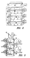
- Fig. 2 is a front view of a stack of assembled roller pairs.
- Fig. 3 is a side view of a stack of assembled roller pairs.
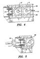
- Fig. 4 is a partially sectioned end view of the bearings for the rolls.
- Fig. 5 is a partially sectioned end view showing the roll adjustment device in detail.
- Fig. 6 is a plan view of the shaft mounted gear box according to the present invention.
- Fig. 7 is an end view of the shaft mounted gear box.
- Fig. 8 is a side elevation of the shaft mounted gear box.
- Fig. 9 is an end view of the belt tensioning device according to the present invention in its maximum takeup position.
- Fig. 10 is an end view of the belt tensioning device in its minimum takeup position.
- Fig. 11 is a front elevation of the belt tensioning device showing the belt guard mounted in place.
- an adjustable roll assembly according to the present invention is shown having a pair of adjacent rolls 1 and 2 having an adjustable gap 20 therebetween.
- the primary driven roll 1 is shown mounted in a pair of bearings 3 for rotation on a shaft 30.
- the driven roll 2 is likewise mounted for rotation in bearings 3' on a shaft 31. It should be appreciated by one skilled in the art that particles passing in the gap 20 between the rolls will be ground, cracked, or otherwise commuted and reduced in particle size.
- Main drive motor 5 rotates the driven roll 1 through a main drive V-belt drive 4.
- Drive of the driven roll 2 is accomplished by power takeoff from roll 1 through an extension of its shaft 30 to a V-belt drive 8 which in turn drives the driven gear box shaft 32 and through a gear reduction in the shaft mounted gear box 9 drives the driven roll shaft 31 and hence the driven roll 2. Details of the power takeoff drive will be more fully explained later.
- the driven roll is urged towards the drive roll by a pair of precision machine screw jacks 11 which jack against the bearings 3′ through a set of strong disc springs 10.
- Positioning of the jack screws is accomplished by motor 17 driving the jack nut through an angle drive 16 and a coupling shaft 15 having a rigid coupling 14 which permits the simultaneous adjustment of the jack nuts and hence the extension of the jacks at both ends of the roll.
- An optical encoder 18 and controller 19 with digital readout 21 permits accurate setting of the gap 20 by automatically adjusting the extension of the machine screw jacks.
- Parallel adjustment between the two jacks may be accomplished by a manually adjusted rigid coupling 14 and the minimum roll gap adjustment can be made manually by a hand wheel 13 or automatic remote control using the optical encoder and controller.
- nonrotating tension base 6 is bolted to the bearing block of the drive roll 1.
- a driving roll tension ring 33 is mounted for rotation on the tension base 6 .
- a similar roll tension ring 34 is mounted for rotation on the gear box extension 12 on gear box 9.
- Gear box 9 has its output on a gear which drives driven roll 2 through shaft 31. Shaft mounted gear box 9 is otherwise free to rotate about shaft 31.
- the V-belt drive 8 transmits power between drive roll shaft 30 and gear box shaft 32.
- the gear box in turn has its power output as previously mentioned on shaft 31. Referring to Fig. 7 it should be apparent that for the roll gap 10 to change, the distance between shaft 30 and shaft 31 will similarly change.
- Shaft mounted gear box 9 is restrained from rotation about shaft 31, about which it is free to rotate by the belt tensioning means of this invention which may be more readily understood by referring to Figs. 9 through 11.
- the belt tensioning device is comprised primarily of two tension rings: a driving roll tension ring 33 and a gear box tension ring 34.
- Each of these tension rings are free to rotate about the respective devices on which they are mounted, i.e., the tension base 6 which is concentric about the drive roll shaft 30 and the gear box extension 12 which is concentric about the driven gear box shaft 32.
- a lug 22 extends from each of the tension rings 33, 34, and are joined together by a pivot 24.
- a pair of fingers 36 which are operably joined together by means of a turnbuckle 35 attached to each of the fingers 36 by a pin 40. It should be appreciated by referring to Figs. 9 and 10 that as the turnbuckle is extended the rings are rotated about the tension base and the gear box extension from a position wherein the lugs 22 are positioned near the centerline providing maximum belt tension to a position shown in Fig. 10 when the turnbuckle is extended wherein minimum belt tension is provided.
- a guard 29 may be mounted to the tensioning device by means of a guard mounted bolt 37 and a spacer 39.
- the bolts cooperate with the guards 29 in a slot 38 which accommodates the required movement between the centerlines of the bolt attachment points on the guard attachment lugs 23.
- tension in the V-belt drive between the drive roll shaft 30 and the driven gear box shaft 32 may be readily accomplished and maintained regardless of the orientation of the tensioning device about the tension base 6 or the gear box extension 12. Since the tensioning device is free to rotate, and the gear box is also free to rotate, it may be appreciated that although the distance between the drive roll shaft and the driven gear box shaft may remain constant, to accomplish belt tension, the dog leg formed between the tensioning device and the offset of the gear box housing provides for the required variation in the gap 20 between the rolls simply by rotation of the dog leg without further adjustment.
- Figs. 2 and 3 show a convenient arrangement of three roll assemblies 26 according to the present invention stacked in a vertical arrangement being fed by a roll feeder 27.
- the convenience of the roll adjusting mechanism provided according to the present invention and the orientation of the roll adjusting device may now be appreciated in relationship to the main drive motors.
- the bearing mounting assembly is shown mounting the bearings 3, 3′ in a U shaped guide 28 which permits the movement of the mounting bearings towards and away from each other. Control of this movement is accomplished by lock screw 41 in the case of the drive roll bearing 3 and by means of the machine screw jacks 11, 15′ providing force against the driven roll bearing 3′ through disc spring assembly 10.
- the disc spring assembly is provided to allow for the rolls to move apart to prevent damage in case of overload created, for example, by tramp material passing between the rolls.
- the guides 28 are formed in a U channel which permits the bearing blocks 3 and 3′ to move in a linear direction apart and conversely together.
- the gap 20 may be automatically adjusted by sensing the gap by means of the optical encoder and adjusting the gap by setting the required gap in the controller 19 which in turn would control the motor which drives the machine screw jacks as previously described.
- the new roll gap is accomplished without further adjustment and operation may be immediately resumed or continued during operation.
Landscapes
- Engineering & Computer Science (AREA)
- Food Science & Technology (AREA)
- Crushing And Grinding (AREA)
Applications Claiming Priority (2)
| Application Number | Priority Date | Filing Date | Title |
|---|---|---|---|
| US467701 | 1983-02-18 | ||
| US07/467,701 US5072887A (en) | 1990-01-19 | 1990-01-19 | Roll mill |
Publications (2)
| Publication Number | Publication Date |
|---|---|
| EP0443715A1 true EP0443715A1 (de) | 1991-08-28 |
| EP0443715B1 EP0443715B1 (de) | 1994-10-26 |
Family
ID=23856773
Family Applications (1)
| Application Number | Title | Priority Date | Filing Date |
|---|---|---|---|
| EP91300374A Expired - Lifetime EP0443715B1 (de) | 1990-01-19 | 1991-01-17 | Walzenmühle |
Country Status (4)
| Country | Link |
|---|---|
| US (1) | US5072887A (de) |
| EP (1) | EP0443715B1 (de) |
| BR (1) | BR9100219A (de) |
| DE (1) | DE69104742T2 (de) |
Cited By (2)
| Publication number | Priority date | Publication date | Assignee | Title |
|---|---|---|---|---|
| EP3552709A1 (de) * | 2018-04-09 | 2019-10-16 | HÄNDLE GmbH Maschinen und Anlagenbau | Walzenmühle |
| CN113840658A (zh) * | 2019-05-09 | 2021-12-24 | 美卓奥图泰美国有限公司 | 破碎装置 |
Families Citing this family (19)
| Publication number | Priority date | Publication date | Assignee | Title |
|---|---|---|---|---|
| DE4243262B4 (de) * | 1992-12-19 | 2004-04-29 | Bühler AG | Verfahren zum Regeln der Vermahlung sowie Anlage zur Durchführung des Verfahrens |
| US5566902A (en) * | 1995-05-12 | 1996-10-22 | California Pellet Mill Company | Roll arrangement for a milling machine, and an inter-roll drive therefor |
| US5609308A (en) * | 1995-10-16 | 1997-03-11 | California Pellet Mill Company | Fine adjustment/quick acting manual actuator for roller mill feed gates |
| US20040081723A1 (en) * | 1996-12-11 | 2004-04-29 | Tetra Holding (Us), Inc. | Flake feed, especially for aquatic animals |
| US7059504B2 (en) * | 2003-07-07 | 2006-06-13 | Karsten Manufacturing Corporation | Extendable and retractable shoulder strap for golf bags |
| US7874504B2 (en) * | 2005-09-26 | 2011-01-25 | Rayco Manufacturing, Inc. | Chipper feed mechanism and throat opening sensor for use therewith |
| CN100577297C (zh) * | 2007-08-07 | 2010-01-06 | 李铋 | 塑料瓶切碎装置 |
| US7867532B2 (en) * | 2007-09-28 | 2011-01-11 | Lextron, Inc. | System and method for flaking grains |
| US20090110766A1 (en) * | 2007-10-25 | 2009-04-30 | Cpm Acquisition Corporation | Coupling for Pelleting Mill |
| CN105562148B (zh) * | 2016-01-20 | 2018-01-16 | 福建安井食品股份有限公司 | 速冻后结块食品的滚轮压散装置 |
| CN107511203A (zh) * | 2016-06-15 | 2017-12-26 | 张荣斌 | 一种双辊式破碎机 |
| CN107497535A (zh) * | 2017-09-11 | 2017-12-22 | 重庆齿轮箱有限责任公司 | 辊压机 |
| SE541957C2 (en) | 2017-11-10 | 2020-01-14 | Metso Sweden Ab | A deflection distributor refitting kit, a method for mounting and a roller crusher comprising such kit |
| US11318474B2 (en) * | 2018-05-14 | 2022-05-03 | Pearson Incorporated | Milling system and method |
| EP3965937A4 (de) | 2019-05-09 | 2023-08-02 | Metso Outotec USA Inc. | Zerkleinerungsvorrichtung |
| CA3139077A1 (en) * | 2019-05-09 | 2020-11-12 | Metso Outotec USA Inc. | Crushing device |
| CN112246340A (zh) * | 2020-09-29 | 2021-01-22 | 百奥美(重庆)生物科技有限公司 | 一种医疗废料破碎装置 |
| BR102021003363B1 (pt) * | 2021-02-23 | 2022-03-08 | Bunge Alimentos S/A | Sistema e método de laminação de grãos |
| WO2024044447A1 (en) | 2022-08-22 | 2024-02-29 | Exxonmobil Chemical Patents Inc. | Methods of pelletizing or briquetting polymer solids |
Citations (3)
| Publication number | Priority date | Publication date | Assignee | Title |
|---|---|---|---|---|
| DE503661C (de) * | 1928-03-30 | 1930-07-25 | Polysius A G G | Quetschwalzenmuehle, deren verschiebbare Walze in einer Geradfuehrung gelagert ist |
| US3884421A (en) * | 1971-03-02 | 1975-05-20 | Simon Ltd Henry | Rollermills |
| DE2519508A1 (de) * | 1975-05-02 | 1976-11-18 | Zwanger Karl A Gmbh | Einstellvorrichtung fuer den abstand zwischen walzen |
Family Cites Families (5)
| Publication number | Priority date | Publication date | Assignee | Title |
|---|---|---|---|---|
| GB1192732A (en) * | 1966-08-31 | 1970-05-20 | Rose Downs & Thompson Ltd | Roll Gap Control |
| CH565589A5 (de) * | 1974-01-18 | 1975-08-29 | Buehler Ag Geb | |
| US4339083A (en) * | 1976-07-16 | 1982-07-13 | Gebrueder Buehler Ag | Apparatus for the grinding of cereal |
| DE3404932A1 (de) * | 1984-02-11 | 1985-08-14 | Gebrüder Bühler AG, Uzwil | Walzwerk |
| DE3723605A1 (de) * | 1987-07-17 | 1989-01-26 | Kloeckner Humboldt Deutz Ag | Zweiwalzenmaschine, wie z. b. walzenpresse |
-
1990
- 1990-01-19 US US07/467,701 patent/US5072887A/en not_active Expired - Lifetime
-
1991
- 1991-01-17 EP EP91300374A patent/EP0443715B1/de not_active Expired - Lifetime
- 1991-01-17 DE DE69104742T patent/DE69104742T2/de not_active Expired - Lifetime
- 1991-01-18 BR BR919100219A patent/BR9100219A/pt not_active IP Right Cessation
Patent Citations (3)
| Publication number | Priority date | Publication date | Assignee | Title |
|---|---|---|---|---|
| DE503661C (de) * | 1928-03-30 | 1930-07-25 | Polysius A G G | Quetschwalzenmuehle, deren verschiebbare Walze in einer Geradfuehrung gelagert ist |
| US3884421A (en) * | 1971-03-02 | 1975-05-20 | Simon Ltd Henry | Rollermills |
| DE2519508A1 (de) * | 1975-05-02 | 1976-11-18 | Zwanger Karl A Gmbh | Einstellvorrichtung fuer den abstand zwischen walzen |
Cited By (2)
| Publication number | Priority date | Publication date | Assignee | Title |
|---|---|---|---|---|
| EP3552709A1 (de) * | 2018-04-09 | 2019-10-16 | HÄNDLE GmbH Maschinen und Anlagenbau | Walzenmühle |
| CN113840658A (zh) * | 2019-05-09 | 2021-12-24 | 美卓奥图泰美国有限公司 | 破碎装置 |
Also Published As
| Publication number | Publication date |
|---|---|
| US5072887A (en) | 1991-12-17 |
| DE69104742D1 (de) | 1994-12-01 |
| EP0443715B1 (de) | 1994-10-26 |
| BR9100219A (pt) | 1991-10-22 |
| DE69104742T2 (de) | 1995-05-11 |
Similar Documents
| Publication | Publication Date | Title |
|---|---|---|
| US5072887A (en) | Roll mill | |
| US4553461A (en) | Rotary web processing apparatus | |
| JP3562541B2 (ja) | 穀物製粉機 | |
| US4015497A (en) | Cable stripping machines with linked cutting and driving wheels | |
| US4015919A (en) | Multi-roll calender for rubber or synthetic plastics materials | |
| JPH0647298A (ja) | ロールミル | |
| US2959364A (en) | Comminution apparatus | |
| CA1221344A (en) | Roller mill construction | |
| US4545541A (en) | Multiple roll roller mill | |
| US5688219A (en) | Device for transporting copies inside a folder equipped with a cutting cylinder | |
| CN109833930A (zh) | 一种液压单传动高压辊磨机 | |
| US6588688B1 (en) | Grinder for comminuting waste material | |
| US4634412A (en) | Belt connector device | |
| KR100200949B1 (ko) | 곡물 및 고추 분쇄기와 그 분쇄방법 | |
| US4173160A (en) | Machine for cutting the lead ends of components mounted at printed-wiring boards | |
| US8215212B2 (en) | On-vehicle brake lathe with indirect drive | |
| US3478972A (en) | Drive for roll crushers | |
| KR100549807B1 (ko) | 롤러 제분기 | |
| EP4344778A3 (de) | Walzenmühle und verfahren zum betrieb einer walzenmühle | |
| US3803769A (en) | Work feeder for a double disc grinder | |
| CN221020422U (zh) | 一种一体式晶体磨面刻槽装置 | |
| US4470224A (en) | Veneer finishing machine | |
| CN222918758U (zh) | 大型送煤输煤的磨煤机 | |
| JPH0653289B2 (ja) | 形鋼の圧延装置 | |
| GB2155808A (en) | Mineral breaker |
Legal Events
| Date | Code | Title | Description |
|---|---|---|---|
| PUAI | Public reference made under article 153(3) epc to a published international application that has entered the european phase |
Free format text: ORIGINAL CODE: 0009012 |
|
| AK | Designated contracting states |
Kind code of ref document: A1 Designated state(s): BE DE FR GB IT NL |
|
| 17P | Request for examination filed |
Effective date: 19920217 |
|
| 17Q | First examination report despatched |
Effective date: 19930303 |
|
| GRAA | (expected) grant |
Free format text: ORIGINAL CODE: 0009210 |
|
| AK | Designated contracting states |
Kind code of ref document: B1 Designated state(s): BE DE GB IT |
|
| REF | Corresponds to: |
Ref document number: 69104742 Country of ref document: DE Date of ref document: 19941201 |
|
| ITF | It: translation for a ep patent filed | ||
| EN | Fr: translation not filed | ||
| PLBE | No opposition filed within time limit |
Free format text: ORIGINAL CODE: 0009261 |
|
| STAA | Information on the status of an ep patent application or granted ep patent |
Free format text: STATUS: NO OPPOSITION FILED WITHIN TIME LIMIT |
|
| 26N | No opposition filed | ||
| REG | Reference to a national code |
Ref country code: GB Ref legal event code: IF02 |
|
| PGFP | Annual fee paid to national office [announced via postgrant information from national office to epo] |
Ref country code: IT Payment date: 20100127 Year of fee payment: 20 |
|
| PGFP | Annual fee paid to national office [announced via postgrant information from national office to epo] |
Ref country code: GB Payment date: 20100125 Year of fee payment: 20 Ref country code: DE Payment date: 20100127 Year of fee payment: 20 Ref country code: BE Payment date: 20100121 Year of fee payment: 20 |
|
| BE20 | Be: patent expired |
Owner name: *CALIFORNIA PELLET MILL CY Effective date: 20110117 |
|
| REG | Reference to a national code |
Ref country code: GB Ref legal event code: PE20 Expiry date: 20110116 |
|
| PG25 | Lapsed in a contracting state [announced via postgrant information from national office to epo] |
Ref country code: GB Free format text: LAPSE BECAUSE OF EXPIRATION OF PROTECTION Effective date: 20110116 |
|
| PG25 | Lapsed in a contracting state [announced via postgrant information from national office to epo] |
Ref country code: DE Free format text: LAPSE BECAUSE OF EXPIRATION OF PROTECTION Effective date: 20110117 |