EP0443770A1 - Hartgusswalzennip - Google Patents
Hartgusswalzennip Download PDFInfo
- Publication number
- EP0443770A1 EP0443770A1 EP91301152A EP91301152A EP0443770A1 EP 0443770 A1 EP0443770 A1 EP 0443770A1 EP 91301152 A EP91301152 A EP 91301152A EP 91301152 A EP91301152 A EP 91301152A EP 0443770 A1 EP0443770 A1 EP 0443770A1
- Authority
- EP
- European Patent Office
- Prior art keywords
- web
- chill roll
- roller
- chill
- roll
- Prior art date
- Legal status (The legal status is an assumption and is not a legal conclusion. Google has not performed a legal analysis and makes no representation as to the accuracy of the status listed.)
- Granted
Links
Images

Classifications
-
- B—PERFORMING OPERATIONS; TRANSPORTING
- B41—PRINTING; LINING MACHINES; TYPEWRITERS; STAMPS
- B41F—PRINTING MACHINES OR PRESSES
- B41F23/00—Devices for treating the surfaces of sheets, webs, or other articles in connection with printing
- B41F23/04—Devices for treating the surfaces of sheets, webs, or other articles in connection with printing by heat drying, by cooling, by applying powders
- B41F23/0476—Cooling
- B41F23/0479—Cooling using chill rolls
Definitions
- This invention relates to a method and means for ensuring substantial contact between a web that moves lengthwise in one direction and a cylindrical surface of a roller around which the web has partial wrapping engagement and which rotates to have the peripheral speed of its said surface match the lengthwise speed of the web.
- a lengthwise moving web is, at some point in its path, brought into partial wrapping engagement around a rotating roller so that the web can have intimate contact with the cylindrical surface of the roller for heat transfer or for some other purpose.
- a problem that has heretofore persisted in connection with such processes is that there is a tendency for a film of air to intrude between the web and the cylindrical surface of the roller, preventing the desired contact between them.
- the air film may allow solvent to condense on the chill roll surface, forming rather thick layers of ribbons of condensate that the web intermittently reabsorbs in sufficient amounts to resoften the ink.
- Heatset inks require residual solvent levels of about 10% to 15% in the final product to maintain product quality. Once heated, these solvents continue to evaporate as long as the web temperature is above about 170°F. As web lift off begins, solvent starts to accumulate on the chill roll. Actual accumulation amounts are dependent on coverage, tension, speed and dryer operating parameters.
- the patent recognizes that blowing air directly towards the web in an effort to force it into contact with the drum would normally be ineffectual because the air jet or jets, after impacting the web, would be deflected or redirected by it into flow along its surface that would produce a lift effect; and "the lift effect of the redirected jets is sufficiently great so that it tends to nullify the pressure exerted by the jets".
- Gardner's air bar has a pair of outlets which are spaced apart by a small distance in the direction of movement of the web and from which air jets issue towards the web at opposite substantially oblique angles to its surface such that they converge towards one another.
- the convergent air jets are said to produce a pressure zone between the air bar and the web, in the region between the outlets from which they are emitted, and the patent states that "the pressure exerted over the relatively large area of the pressure zone [is] so much greater than the lift effect of the redirected jets that the latter ceases to be of any consequence".
- the expedient disclosed by Gardner may be of value where web tension is rather high - as expressly contemplated by the patent - and with moderate web speeds, but it is doubtful that it would be effective with relatively high web speeds and small or moderate tensions. In all cases it would require a substantially high rate of air flow to be effective and would therefore consume a substantial amount of energy in its normal operation.
- U.S. Patent No. 4,369,584, assigned to the assignee of the instant invention discloses the use of a high velocity air jet to force a moving web into contact with a rotating roller, such as a chill roll. Although such an approach has been successful, the jet demands a substantial energy requirement to generate the high pressure air.
- U.S. Patent No. 4,462,169 also assigned to the assignee of the instant invention, discloses a chill nip which depends upon the use of an interference fit.
- two cooperating rolls form an adjustable nip clearance maintained at about 0.001 inches less than the thickness of the web.
- the resulting physical compression of the web can damage not only the printed surface, but the web itself.
- the instant invention provides a method and means for applying sufficient downward force onto a moving web to hold it substantially in contact with a rotating roller, such as a chill roll.
- a rotating roller such as a chill roll.
- an additional roller such as a chill roll is stacked over or is slightly offset from an existing roller with which the moving web is desired to be in partial wrapping engagement.
- the two rollers create a nip through which the web passes.
- the additional roller is aligned to close clearances with the existing roller such that any air gaps are forcibly removed.
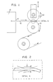
- FIG. 1 a portion of a dryer assembly 10 is shown, out of which web 12 is driven through web slot 14.
- the freshly coated or imprinted web 12 emerges from the dryer 10 in a heated state. Cooling of the web 12 is accomplished by passing it over the surface of a cooling cylinder 15, known in the art as a chill roll.
- the chill roll 15 functions to transfer heat from the hot web 12 emerging from the dryer 10 to the medium cooling the chill roll, such as water, to thereby cool the web 12 and solidify the ink or coating applied to the web 12.
- the web moves lengthwise from dryer 10 to chill roll 15 at speeds in the order of 1000-3000 fpm.
- Chill roll 15 rotates at an appropriate speed such that the peripheral speed of its surface is substantially matched to the web speed.
- means is provided to create an opposed force that would force web 12 in close enough proximity to chill roll 15 so as to avoid the formation of condensate.
- the opposed force is preferably created by a chill nip roll 20 positioned so as to create a nip with chill roll 15.
- the nip is larger than the thickness of web 12 so as to avoid a calendaring effect.
- the center of chill nip roll 20 is positioned directly over the center of chill roll 15 as is shown in Fig. 1.
- the center of chill nip roll 20 need not be positioned directly over the center of chill roll 15.
- the operative factor is to create the sufficient opposed force to mitigate web lift-off and the resultant solvent condensate accumulation.
- Chill nip roll 20 can be positioned at a point other than tangency and thus offset from chill roll 15 to create a slight "S" wrap in one direction.
- the chill nip roll 20 can be positioned at a point upstream of the chill roll 15 along a path of web travel around chill roll 15, and lowered to create the additional bend the web 12 has to travel through.
- This orientation utilizes web momentum and apparent centrifugal force to drive the web into roll 15 to help eliminate the air gap.
- the nip is formed with the first chill roll that the web encounters as it exits the dryer.
- the web temperature after the first chill roll is low enough so that the solvent evaporation rate is sufficiently small from the standpoint of deleterious solvent condensation on subsequent chill rolls.
- the nip could be formed there as well.
- Fig. 3 shows an example of a supporting apparatus for chill nip roll 20.
- the chill nip roll 20 is mounted on each end by self aligning ball bearings which are themselves mounted to vertical plates 30 supported at the top to one flat plate 31.
- the flat plate 31 rests across two horizontal members 32 which pivot about a single shaft 33 at the other create an opposed air wedging force bringing the web clearance from the roll 20 and the web clearance from the roll 15 into equilibrium.
- the additional force associated with weight and position of roll 20, web tension and web weight allows the clearance from the chill roll 15 to the web to be less than that necessary to achieve deleterious solvent condensate formation.
- the diameter of the roll 20 is not critical so long as the roll can be adequately cooled to keep the roll surface temperature below the ink pick-off point, and its weight in addition to the weight of the supporting mechanism supplied enough downward force to overcome the lift-off force.
- the advantages of a larger roll 20 diameter creating a greater downward air wedge force will be apparent to those skilled in the art.
- the chill nip roll 20 is a cooled, rotating chill roll supported vertically and positioned by stops.
- the device should have a design operating clearance about equal to the sum of the chill roll and nip roll radial run-outs above the normal thickness of web 12.
- the rolls should be designed for zero radial run-out.
- Radial run-out is defined as the total variation in a direction perpendicular to the axis of rotation of a reference surface from a surface of revolution. Radial run-out includes eccentricity and out of roundness, and is usually about twice the eccentricity.
- the roll 20 is rotated at speeds substantially equal to or greater than the speed of the web, and to match web direction.
- the clearance between chill nip roll 20 and chill roll 15 is controlled by limiting stops to insure adequate downward repositioning of the web 12 and allowing for a slight amount of web compression as a result of chill roll radial run-out and variations in web thickness. Solvent condensate is not problematic with chill nip roll 20, as it is not exposed to the amount of contact area that takes place with chill roll 15. end of the mechanism.
- the horizontal movement is controlled by four adjustment dowels.
- the chill nip mechanism is raised and lowered using pressurized air bags 35. Other suitable means for raising and lowering the mechanism include pneumatic cylinders.
- There are two adjustable stops 36 which consist of commercially available shaft phase coupling harmonic drives with a 100 to 1 turning ratio.
- the chill nip roll is cooled by water which enters one end 37 and leaves the other through hydraulic unions.
- a safety mechanism shown generally at 40 included which automatically slides into place disallowing any lowering of the nip roll 20 after it has been raised for whatever reason.
- the mechanism 40 comprises a spring loaded bar that slides under the horizontal plates 32 to physically prevent downward movement of the mechanism in the case of an emergency stop, shutdown (less than 10% speed) or normal stop.
- a limit switch At one end of the mechanism 40 is a limit switch that detects that the operator has pushed in the safety bar allowing the nip roll to be lowered into position, so as to provide added safety.
- the chill nip 20 automatically lifts up when there is an emergency stop, press is less than 10% speed or the operator pushes the manual stop button. Also, the controls can be made to raise the nip roll when a web splice is coming through the system.
- the chill nip roll 20 is motor/belt driven by drive 50.
- the drive package can be made to match the first chill roll speed or it can bring the nip roll 20 up to some higher speed if deemed necessary.
- the whole mechanism moves up and down inside two side plates 70 which are mounted on an existing chill stand at 75. A brake 60 should also be incorporated into the device for safety reasons.
- the press operator first makes preliminary adjustments to the mechanical stops in order to set the roll-to-roll gap. These adjustments are based on web weight. While in the raised position, the operator then brings the chill nip roll up to matching speed with the press, through the engagement of direct driven clutching or the starting of a motor (whichever applies). Following the release of any safety devices, the nip roll is then lowered into position where final adjustments to the mechanical stops is made to enhance operating results.
Landscapes
- Engineering & Computer Science (AREA)
- Mechanical Engineering (AREA)
- Supply, Installation And Extraction Of Printed Sheets Or Plates (AREA)
- Advancing Webs (AREA)
- Preliminary Treatment Of Fibers (AREA)
Applications Claiming Priority (2)
| Application Number | Priority Date | Filing Date | Title |
|---|---|---|---|
| US07/482,465 US5111595A (en) | 1990-02-21 | 1990-02-21 | Chill roll nip |
| US482465 | 1990-02-21 |
Publications (2)
| Publication Number | Publication Date |
|---|---|
| EP0443770A1 true EP0443770A1 (de) | 1991-08-28 |
| EP0443770B1 EP0443770B1 (de) | 1996-10-02 |
Family
ID=23916187
Family Applications (1)
| Application Number | Title | Priority Date | Filing Date |
|---|---|---|---|
| EP91301152A Expired - Lifetime EP0443770B1 (de) | 1990-02-21 | 1991-02-13 | Hartgusswalzennip |
Country Status (5)
| Country | Link |
|---|---|
| US (1) | US5111595A (de) |
| EP (1) | EP0443770B1 (de) |
| JP (1) | JP3059508B2 (de) |
| CA (1) | CA2036288C (de) |
| DE (1) | DE69122416T2 (de) |
Cited By (1)
| Publication number | Priority date | Publication date | Assignee | Title |
|---|---|---|---|---|
| CN118361937A (zh) * | 2024-05-08 | 2024-07-19 | 汕头市鼎泰丰实业有限公司 | 一种热风式布料烘干装置 |
Families Citing this family (5)
| Publication number | Priority date | Publication date | Assignee | Title |
|---|---|---|---|---|
| US5416984A (en) * | 1993-11-18 | 1995-05-23 | Heidelberg Druckmaschinen Ag | Apparatus and method for deflecting a web |
| US5571564A (en) * | 1995-03-20 | 1996-11-05 | Advance Systems, Inc. | Apparatus and method for preventing ink resoftening on a printed web as the web travels over a chill roll |
| US5571563A (en) * | 1995-03-20 | 1996-11-05 | Advance Systems, Inc. | Apparatus and method for preventing ink resoftening on a printed web as the web travels over a chill roll |
| JP6650228B2 (ja) * | 2015-08-17 | 2020-02-19 | 株式会社神戸製鋼所 | 繊維強化熱可塑性樹脂テープの製造装置及び製造方法 |
| DE102017119576A1 (de) * | 2017-08-25 | 2019-02-28 | Klomfass Gierlings & Partner GbR (vertretungsberechtigter Gesellschafter Michael Gierlings, 40723 Hilden) | Vorrichtung zum Kaschieren eines Substrates mit einem thermoplastischen Beschichtungsmaterial |
Citations (5)
| Publication number | Priority date | Publication date | Assignee | Title |
|---|---|---|---|---|
| US3452447A (en) * | 1967-05-25 | 1969-07-01 | Thomas A Gardner | Web positioning means and method |
| DE2925985A1 (de) * | 1978-07-13 | 1980-01-24 | Grace W R & Co | Beruehrungslose bahnabstuetzung |
| US4218833A (en) * | 1978-01-27 | 1980-08-26 | Spooner Edmeston Engineering Limited | Float treatment apparatus |
| US4369584A (en) * | 1981-04-16 | 1983-01-25 | W. R. Grace & Co. | Preventing air film between web and roller |
| DE3324130A1 (de) * | 1983-07-05 | 1985-05-15 | Franz 4834 Harsewinkel Böhnensieker | Verfahren und vorrichtung zum trocknen bedruckter oder gefaerbter bahnen mittels waerme |
Family Cites Families (16)
| Publication number | Priority date | Publication date | Assignee | Title |
|---|---|---|---|---|
| US1890832A (en) * | 1932-12-13 | Method for drying thin cellulose sheets | ||
| GB189408546A (en) * | 1894-04-30 | 1895-02-02 | Blundell S London Copper And B | Improvements in or relating to Ships' Water Closets. |
| US1144896A (en) * | 1914-08-29 | 1915-06-29 | Alfred Thomas Fosbraey | Coated-paper-drying apparatus. |
| US1890833A (en) * | 1927-05-18 | 1932-12-13 | Heyden Chem Fab | Means for drying long webs of thin cellulose sheets |
| US2131257A (en) * | 1937-08-13 | 1938-09-27 | Curtis Publishing Company | Drying apparatus for web printing presses |
| US2526318A (en) * | 1948-02-10 | 1950-10-17 | Us Rubber Co | Sheet finishing apparatus |
| US2534973A (en) * | 1949-03-02 | 1950-12-19 | Gen Electric | Cooling apparatus |
| US2855190A (en) * | 1956-03-02 | 1958-10-07 | Rieger Printing Ink Company Lt | Apparatus for drying printing inks |
| US4016030A (en) * | 1975-01-29 | 1977-04-05 | Fort Howard Paper Company | Calendering paper containing thermoplastic contaminants |
| GB1561897A (en) * | 1976-10-20 | 1980-03-05 | Ciba Geigy Ag | Photographic drying apparatus |
| CH617602A5 (de) * | 1976-10-21 | 1980-06-13 | Escher Wyss Ag | |
| US4263724A (en) * | 1979-06-14 | 1981-04-28 | Vits-Maschinenbau Gmbh | Traveling web drying apparatus |
| US4384514A (en) * | 1981-03-03 | 1983-05-24 | Consolidated-Bathurst Inc. | Nip control method and apparatus |
| FI63078C (fi) * | 1982-04-06 | 1983-04-11 | Tampella Oy Ab | Foerfarande och anordning foer torkning av en pappersbana eller liknande |
| US4743334A (en) * | 1986-02-19 | 1988-05-10 | D&K Custom Machine Design, Inc. | Double sided laminating machine |
| DE3706541A1 (de) * | 1987-02-28 | 1988-09-08 | Voith Gmbh J M | Vorrichtung zum stabilisieren des laufes einer warenbahn, insbesondere zum stabilisieren einer papierbahn in der trockenpartie einer papiermaschine |
-
1990
- 1990-02-21 US US07/482,465 patent/US5111595A/en not_active Expired - Lifetime
-
1991
- 1991-02-13 EP EP91301152A patent/EP0443770B1/de not_active Expired - Lifetime
- 1991-02-13 DE DE69122416T patent/DE69122416T2/de not_active Expired - Fee Related
- 1991-02-13 CA CA002036288A patent/CA2036288C/en not_active Expired - Lifetime
- 1991-02-21 JP JP3049134A patent/JP3059508B2/ja not_active Expired - Lifetime
Patent Citations (5)
| Publication number | Priority date | Publication date | Assignee | Title |
|---|---|---|---|---|
| US3452447A (en) * | 1967-05-25 | 1969-07-01 | Thomas A Gardner | Web positioning means and method |
| US4218833A (en) * | 1978-01-27 | 1980-08-26 | Spooner Edmeston Engineering Limited | Float treatment apparatus |
| DE2925985A1 (de) * | 1978-07-13 | 1980-01-24 | Grace W R & Co | Beruehrungslose bahnabstuetzung |
| US4369584A (en) * | 1981-04-16 | 1983-01-25 | W. R. Grace & Co. | Preventing air film between web and roller |
| DE3324130A1 (de) * | 1983-07-05 | 1985-05-15 | Franz 4834 Harsewinkel Böhnensieker | Verfahren und vorrichtung zum trocknen bedruckter oder gefaerbter bahnen mittels waerme |
Cited By (1)
| Publication number | Priority date | Publication date | Assignee | Title |
|---|---|---|---|---|
| CN118361937A (zh) * | 2024-05-08 | 2024-07-19 | 汕头市鼎泰丰实业有限公司 | 一种热风式布料烘干装置 |
Also Published As
| Publication number | Publication date |
|---|---|
| CA2036288C (en) | 2000-12-26 |
| CA2036288A1 (en) | 1991-08-22 |
| DE69122416T2 (de) | 1997-02-20 |
| EP0443770B1 (de) | 1996-10-02 |
| JPH04216053A (ja) | 1992-08-06 |
| US5111595A (en) | 1992-05-12 |
| JP3059508B2 (ja) | 2000-07-04 |
| DE69122416D1 (de) | 1996-11-07 |
Similar Documents
| Publication | Publication Date | Title |
|---|---|---|
| US4369584A (en) | Preventing air film between web and roller | |
| EP0483092B1 (de) | Aufwickelverfahren und Aufwickelvorrichtung | |
| CA1201927A (en) | Webbing system | |
| FI100467B (fi) | Menetelmä ja laite rainan rullauksessa | |
| JP2819283B2 (ja) | 連続紙走行張力制御装置 | |
| US5988557A (en) | Method and apparatus for the winding up of a paper web to form a roll | |
| JP3428852B2 (ja) | ウエブ印刷機の巻付防止装置 | |
| US5111595A (en) | Chill roll nip | |
| EP0157096A1 (de) | Aufwickelmechanismus für Bänder | |
| FI110424B (fi) | Rullain ja menetelmä rainan rullaamiseksi | |
| US20060272287A1 (en) | Apparatus for wrapping including joining of trailing end of wrapping material to leading end of subsequent wrapping material | |
| JPH11216516A (ja) | サイドガイド装置 | |
| CA2328189A1 (en) | Method and apparatus for reeling a traveling paper web | |
| EP0372757B1 (de) | Vorrichtung zum Ausrichten von Bahnen | |
| CA1282762C (en) | Web reeling method and apparatus | |
| US5087318A (en) | Web-aligning apparatus | |
| CA2190926A1 (en) | Surface Winder | |
| US5615610A (en) | Web capturing device | |
| US5580012A (en) | Shingled linerless label rolls | |
| US3806018A (en) | Roll systems for webs of material | |
| US7159334B2 (en) | Web coating machine | |
| JP2003505312A (ja) | ウェブを巻き取る装置および方法 | |
| EP0757807A1 (de) | System und verfahren zur vermeidung von schlupf beim transport eines aufzeichnungsträgers in einem elektrografischen druck- oder kopiergerät | |
| EP1345831B9 (de) | Vorrichtung und verfahren zum wickeln von bahnen | |
| JP2004516207A (ja) | ウェブを巻取る装置および方法 |
Legal Events
| Date | Code | Title | Description |
|---|---|---|---|
| PUAI | Public reference made under article 153(3) epc to a published international application that has entered the european phase |
Free format text: ORIGINAL CODE: 0009012 |
|
| AK | Designated contracting states |
Kind code of ref document: A1 Designated state(s): DE FR GB IT |
|
| 17P | Request for examination filed |
Effective date: 19920225 |
|
| 17Q | First examination report despatched |
Effective date: 19930804 |
|
| GRAH | Despatch of communication of intention to grant a patent |
Free format text: ORIGINAL CODE: EPIDOS IGRA |
|
| GRAH | Despatch of communication of intention to grant a patent |
Free format text: ORIGINAL CODE: EPIDOS IGRA |
|
| GRAA | (expected) grant |
Free format text: ORIGINAL CODE: 0009210 |
|
| AK | Designated contracting states |
Kind code of ref document: B1 Designated state(s): DE FR GB IT |
|
| REF | Corresponds to: |
Ref document number: 69122416 Country of ref document: DE Date of ref document: 19961107 |
|
| ITF | It: translation for a ep patent filed | ||
| ET | Fr: translation filed | ||
| PLBE | No opposition filed within time limit |
Free format text: ORIGINAL CODE: 0009261 |
|
| STAA | Information on the status of an ep patent application or granted ep patent |
Free format text: STATUS: NO OPPOSITION FILED WITHIN TIME LIMIT |
|
| 26N | No opposition filed | ||
| REG | Reference to a national code |
Ref country code: FR Ref legal event code: TP |
|
| REG | Reference to a national code |
Ref country code: GB Ref legal event code: 732E |
|
| PGFP | Annual fee paid to national office [announced via postgrant information from national office to epo] |
Ref country code: DE Payment date: 19991231 Year of fee payment: 10 |
|
| PGFP | Annual fee paid to national office [announced via postgrant information from national office to epo] |
Ref country code: GB Payment date: 20000209 Year of fee payment: 10 |
|
| PGFP | Annual fee paid to national office [announced via postgrant information from national office to epo] |
Ref country code: FR Payment date: 20000210 Year of fee payment: 10 |
|
| PG25 | Lapsed in a contracting state [announced via postgrant information from national office to epo] |
Ref country code: GB Free format text: LAPSE BECAUSE OF NON-PAYMENT OF DUE FEES Effective date: 20010213 |
|
| GBPC | Gb: european patent ceased through non-payment of renewal fee |
Effective date: 20010213 |
|
| PG25 | Lapsed in a contracting state [announced via postgrant information from national office to epo] |
Ref country code: FR Free format text: LAPSE BECAUSE OF NON-PAYMENT OF DUE FEES Effective date: 20011031 |
|
| REG | Reference to a national code |
Ref country code: FR Ref legal event code: ST |
|
| PG25 | Lapsed in a contracting state [announced via postgrant information from national office to epo] |
Ref country code: DE Free format text: LAPSE BECAUSE OF NON-PAYMENT OF DUE FEES Effective date: 20011201 |
|
| PG25 | Lapsed in a contracting state [announced via postgrant information from national office to epo] |
Ref country code: IT Free format text: LAPSE BECAUSE OF NON-PAYMENT OF DUE FEES;WARNING: LAPSES OF ITALIAN PATENTS WITH EFFECTIVE DATE BEFORE 2007 MAY HAVE OCCURRED AT ANY TIME BEFORE 2007. THE CORRECT EFFECTIVE DATE MAY BE DIFFERENT FROM THE ONE RECORDED. Effective date: 20050213 |