EP0443779A2 - Plastic valve bush for dynamic multi-port valve - Google Patents
Plastic valve bush for dynamic multi-port valve Download PDFInfo
- Publication number
- EP0443779A2 EP0443779A2 EP91301201A EP91301201A EP0443779A2 EP 0443779 A2 EP0443779 A2 EP 0443779A2 EP 91301201 A EP91301201 A EP 91301201A EP 91301201 A EP91301201 A EP 91301201A EP 0443779 A2 EP0443779 A2 EP 0443779A2
- Authority
- EP
- European Patent Office
- Prior art keywords
- bush
- segments
- valve
- fingers
- apertures
- Prior art date
- Legal status (The legal status is an assumption and is not a legal conclusion. Google has not performed a legal analysis and makes no representation as to the accuracy of the status listed.)
- Granted
Links
Images


Classifications
-
- F—MECHANICAL ENGINEERING; LIGHTING; HEATING; WEAPONS; BLASTING
- F16—ENGINEERING ELEMENTS AND UNITS; GENERAL MEASURES FOR PRODUCING AND MAINTAINING EFFECTIVE FUNCTIONING OF MACHINES OR INSTALLATIONS; THERMAL INSULATION IN GENERAL
- F16K—VALVES; TAPS; COCKS; ACTUATING-FLOATS; DEVICES FOR VENTING OR AERATING
- F16K27/00—Construction of housing; Use of materials therefor
- F16K27/04—Construction of housing; Use of materials therefor of sliding valves
- F16K27/041—Construction of housing; Use of materials therefor of sliding valves cylindrical slide valves
-
- F—MECHANICAL ENGINEERING; LIGHTING; HEATING; WEAPONS; BLASTING
- F16—ENGINEERING ELEMENTS AND UNITS; GENERAL MEASURES FOR PRODUCING AND MAINTAINING EFFECTIVE FUNCTIONING OF MACHINES OR INSTALLATIONS; THERMAL INSULATION IN GENERAL
- F16K—VALVES; TAPS; COCKS; ACTUATING-FLOATS; DEVICES FOR VENTING OR AERATING
- F16K11/00—Multiple-way valves, e.g. mixing valves; Pipe fittings incorporating such valves
- F16K11/02—Multiple-way valves, e.g. mixing valves; Pipe fittings incorporating such valves with all movable sealing faces moving as one unit
- F16K11/06—Multiple-way valves, e.g. mixing valves; Pipe fittings incorporating such valves with all movable sealing faces moving as one unit comprising only sliding valves, i.e. sliding closure elements
- F16K11/065—Multiple-way valves, e.g. mixing valves; Pipe fittings incorporating such valves with all movable sealing faces moving as one unit comprising only sliding valves, i.e. sliding closure elements with linearly sliding closure members
- F16K11/07—Multiple-way valves, e.g. mixing valves; Pipe fittings incorporating such valves with all movable sealing faces moving as one unit comprising only sliding valves, i.e. sliding closure elements with linearly sliding closure members with cylindrical slides
-
- Y—GENERAL TAGGING OF NEW TECHNOLOGICAL DEVELOPMENTS; GENERAL TAGGING OF CROSS-SECTIONAL TECHNOLOGIES SPANNING OVER SEVERAL SECTIONS OF THE IPC; TECHNICAL SUBJECTS COVERED BY FORMER USPC CROSS-REFERENCE ART COLLECTIONS [XRACs] AND DIGESTS
- Y10—TECHNICAL SUBJECTS COVERED BY FORMER USPC
- Y10T—TECHNICAL SUBJECTS COVERED BY FORMER US CLASSIFICATION
- Y10T137/00—Fluid handling
- Y10T137/8593—Systems
- Y10T137/86493—Multi-way valve unit
- Y10T137/86574—Supply and exhaust
- Y10T137/8667—Reciprocating valve
- Y10T137/86694—Piston valve
- Y10T137/8671—With annular passage [e.g., spool]
-
- Y—GENERAL TAGGING OF NEW TECHNOLOGICAL DEVELOPMENTS; GENERAL TAGGING OF CROSS-SECTIONAL TECHNOLOGIES SPANNING OVER SEVERAL SECTIONS OF THE IPC; TECHNICAL SUBJECTS COVERED BY FORMER USPC CROSS-REFERENCE ART COLLECTIONS [XRACs] AND DIGESTS
- Y10—TECHNICAL SUBJECTS COVERED BY FORMER USPC
- Y10T—TECHNICAL SUBJECTS COVERED BY FORMER US CLASSIFICATION
- Y10T137/00—Fluid handling
- Y10T137/8593—Systems
- Y10T137/86493—Multi-way valve unit
- Y10T137/86879—Reciprocating valve unit
Definitions
- This invention relates to valve bushes and has particular reference to valve bushes for dynamic multi-port valves, for example three or five port valves.
- a dynamic five port valve there is an outer hollow cylindrical member through which extend five ports for the ingress and egress of fluid, normally compressed air.
- a hollow, generally cylindrical valve bush which includes five axially spaced sets of circumferential apertures and a series of lands to locate a series of ′o′ - rings.
- the two end sets, and the central set, of apertures are of relatively large diameter whereas the two intermediate sets of apertures are of very small diameter.
- the lands define locations for six ′o′ - rings which separate the sets of apertures from one other and from the ends of the bush. Additionally it is convenient to provide a further pair of lands for locating end ′o′ - rings that serve to seal the valve bush in a valve body.
- a piston which includes sets of ′o′ -rings and annular relieved portions.
- the piston is axially moveable within the bush so as to make the desired connections between the valve ports.
- certain of the ′o′ rings on the inner piston have to traverse the two intermediate sets of small diameter apertures.
- the ′o′ - rings must be supported properly during their movement and it is for this reason that the two intermediate sets of apertures are of very small diameter, so that the ligaments between the apertures can support the ′o′rings during their traverse across the apertures. It has been the practice, hitherto, to form the valve bush from brass and to drill the small diameter apertures individually with a fine drill.
- Dynamic three port valves are, in principle, identical but of course utilise a bush having correspondingly fewer sets of large and small diameter apertures and O-ring lands.
- a bush for a dynamic multi-port valve is referred to as a multi-port valve bush of the type set forth.
- a multi-port valve bush of the type set forth characterised in that the bush is formed of plastics material, in a plurality of hollow cylindrical segments interengaged in end-to-end relationship to form the bush, the or each intermediate set of small diameter apertures being in the form of a plurality of apertures, for example rectangular slots, defined by facing end surfaces of two adjacent segments and by a plurality of spaced fingers extending axially from said end surfaces.
- the fingers of one segment preferably intermesh, in spaced parallel relationship, with fingers of the adjacent segment and may lock into respective recesses formed in the facing end surface of, and between the fingers of, the adjacent segment.
- the respective ends of the fingers of one segment may simply abut the respective ends of corresponding fingers of the adjacent segment.
- Adjacent segments may be interengaged by pips and recesses moulded integrally on said segments.
- the pips may, for example, be a snap fit in their respective recesses or may be secured therein by an adhesive or weld.
- the segments of which there will, for example, be two in a three port valve and three in a five port valve, may be formed by injection moulding.
- the present invention also provides a dynamic seal multi-port valve in which the valve bush is as is set out above.
- the valve may be operated pneumatically or mechanically, for example by means of springs or levers, as is conventional.
- this shows a dynamic seal five port valve essentially comprising an outer casing 1 secured to a base member 2 by screws, not shown.
- a series of air passages such as passage 3 extends through the base member 2 and through one wall of the outer casing 1.
- Located within the casing 1 is a fixed valve bush 4 and located within the valve bush 4 is an axially moveable piston 5 having three annular recesses 5′, 5 ⁇ , 5′′′ formed on its external surface. It can be seen that the piston 5 carries with it a series of ′o′ - rings located on lands 6,7,8 and 9 which serve to isolate the recesses 5′, 5 ⁇ , 5′′′ from one another.
- the valve bush 4 has a series of apertures along the axial length of the bush and supports a series of ′o′ - rings 14,15,16,17,18 and 19, which together with the casing 1 define a series of annular chambers in communication with the ports 3, 10, 11, 12 and 13.
- the desired interconnection between these ports thus occurs via the internal piston.
- ports 10 and 11 are interconnected, as are ports 3 and 12, but port 13 is blanked off.
- ports 12 and 13 are connected, as are ports 3 and 11 and port 10 is blanked off.
- Outer ′o′ - rings 20 and 21 seal the bush in the casing.
- the ports 3,10,11,12 and 13 are staggered within the base 2.
- the piston is moved by air pressure, supplied to either end via ports 22,23.
- Such a dynamic seal five port valve is well known and conventionally incorporates a brass bush 4, as illustrated in Figure 4 to 6.
- the brass bush is in the form of a hollow cylinder with a central set of large diameter apertures (or “ports"), 24, and two outer sets of apertures 25, 26 spaced axially from the central set of apertures. Located between the three sets of large diameter apertures are two intermediate sets of small diameter holes shown at 27,28. These holes are shown in an enlarged view in Figure 6.
- the holes are individually drilled and in the case of a 1 ⁇ 2 ⁇ diameter bush there may be, for example, as many as 480 such holes.
- Such existing brass bushes are extremely reliable but are expensive to manufacture. Thus not only do they have to be drilled with a very large number of holes, but also they have to be machined to produce the lands (such as land 30 with its associated annular flanges 31,32) which locate the ′o′ - rings - in the case of land 30, ′o′ - ring 20.
- the entire bush is of injection moulded plastics material.
- a typical plastics material would be ABS.
- the valve bush comprises three separately moulded segments, namely segments 33,34 and 35. It can be seen that segments 33 and 34 are identical and, therefore, only two moulds are required to produce the bush. As will be appreciated, the lands, such as land 36 and associated flanges 37,38 are integrally moulded and the large diameter apertures 39,40,41 would be formed by pins forming part of the mould tool. These apertures 39,40 and 41 correspond to ports 25,24,26 of the brass bush described above with reference to Figs 4 to 6.
- the central segment 35 has a plurality of integrally moulded, axially extending, spaced fingers 42,43 on each end which intermesh, in spaced parallel relationship with like fingers 44,45 formed on the adjacent end segments 33,34.
- the tips 46 of the fingers engage in respective recesses 46′ formed in the end face of the adjacent segment, as shown in Figure 10.
- each slot may be about 2mm long and 1mm wide.
- central segment 35 is provided with integral pips 47,48 which engage integral recesses 49,50 formed in the end segments 33,34 thereby locking the segments together.
- valve bush that can readily be assembled from relatively simple mouldings, whereby the complex and expensive drilling and machining operations associated with the prior brass bushes is avoided.
- plastics bushes may likewise be produced for use in other multi-port dynamic valves, for example 3-port valves.
Landscapes
- Engineering & Computer Science (AREA)
- General Engineering & Computer Science (AREA)
- Mechanical Engineering (AREA)
- Multiple-Way Valves (AREA)
- Valve Housings (AREA)
- Glass Compositions (AREA)
- Magnetically Actuated Valves (AREA)
- Valve-Gear Or Valve Arrangements (AREA)
- Lift Valve (AREA)
Abstract
Description
- This invention relates to valve bushes and has particular reference to valve bushes for dynamic multi-port valves, for example three or five port valves.
- In a dynamic five port valve there is an outer hollow cylindrical member through which extend five ports for the ingress and egress of fluid, normally compressed air. Within the cylindrical member there is a hollow, generally cylindrical valve bush which includes five axially spaced sets of circumferential apertures and a series of lands to locate a series of ′o′ - rings. The two end sets, and the central set, of apertures are of relatively large diameter whereas the two intermediate sets of apertures are of very small diameter. On the outside of the bush the lands define locations for six ′o′ - rings which separate the sets of apertures from one other and from the ends of the bush. Additionally it is convenient to provide a further pair of lands for locating end ′o′ - rings that serve to seal the valve bush in a valve body.
- Within the valve bush there is located a piston which includes sets of ′o′ -rings and annular relieved portions. The piston is axially moveable within the bush so as to make the desired connections between the valve ports. In such a dynamic seal valve, certain of the ′o′ rings on the inner piston have to traverse the two intermediate sets of small diameter apertures. For a practical dynamic valve in which the ′o′ - ring seal has a sufficient life to be commercially useful, the ′o′ - rings must be supported properly during their movement and it is for this reason that the two intermediate sets of apertures are of very small diameter, so that the ligaments between the apertures can support the ′o′rings during their traverse across the apertures. It has been the practice, hitherto, to form the valve bush from brass and to drill the small diameter apertures individually with a fine drill.
- Such brass bushes work very well but are expensive to manufacture because of the need to drill the holes individually.
- Dynamic three port valves are, in principle, identical but of course utilise a bush having correspondingly fewer sets of large and small diameter apertures and O-ring lands. Hereinafter such a bush for a dynamic multi-port valve is referred to as a multi-port valve bush of the type set forth.
- By the present invention there is provided a multi-port valve bush of the type set forth, characterised in that the bush is formed of plastics material, in a plurality of hollow cylindrical segments interengaged in end-to-end relationship to form the bush, the or each intermediate set of small diameter apertures being in the form of a plurality of apertures, for example rectangular slots, defined by facing end surfaces of two adjacent segments and by a plurality of spaced fingers extending axially from said end surfaces.
- The fingers of one segment preferably intermesh, in spaced parallel relationship, with fingers of the adjacent segment and may lock into respective recesses formed in the facing end surface of, and between the fingers of, the adjacent segment. Alternatively, for example, the respective ends of the fingers of one segment may simply abut the respective ends of corresponding fingers of the adjacent segment.
- Adjacent segments may be interengaged by pips and recesses moulded integrally on said segments. The pips may, for example, be a snap fit in their respective recesses or may be secured therein by an adhesive or weld.
- The segments, of which there will, for example, be two in a three port valve and three in a five port valve, may be formed by injection moulding.
- The present invention also provides a dynamic seal multi-port valve in which the valve bush is as is set out above. The valve may be operated pneumatically or mechanically, for example by means of springs or levers, as is conventional.
- The invention will now be described in more detail, by way of example, with reference to the accompanying drawings of which:-
- Figure 1 is a cross section through a dynamic seal five port valve,
- Figure 2 is an end view of Figure 1 along the line of arrow II,
- Figure 3 is a part section of Figure 1 through the base of the valve of Figure 1,
- Figure 4 is an external view of a prior art brass bush,
- Figure 5 is a cross section of Figure 4,
- Figure 6 is an enlarged detail of the holes of Figure 4,
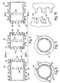
- Figure 7 is an exploded, sectional view of a bush of the invention comprising three segments,
- Figure 8 is a view of Figure 7 along the line VIII-VIII,
- Figure 9 is a section of Figure 7 on the line IX-IX, and
- Figure 10 is an enlarged exploded detail of the junction between adjacent segments of Figure 7.
- Referring to Figure 1, this shows a dynamic seal five port valve essentially comprising an outer casing 1 secured to a
base member 2 by screws, not shown. A series of air passages such aspassage 3 extends through thebase member 2 and through one wall of the outer casing 1. Located within the casing 1 is a fixedvalve bush 4 and located within thevalve bush 4 is an axiallymoveable piston 5 having threeannular recesses 5′, 5˝, 5‴ formed on its external surface. It can be seen that thepiston 5 carries with it a series of ′o′ - rings located onlands recesses 5′, 5˝, 5‴ from one another. Thevalve bush 4 has a series of apertures along the axial length of the bush and supports a series of ′o′ -rings ports ports ports port 13 is blanked off. However, by moving the piston to the right,ports ports port 10 is blanked off. Outer ′o′ -rings ports base 2. The piston is moved by air pressure, supplied to either end viaports - Such a dynamic seal five port valve is well known and conventionally incorporates a
brass bush 4, as illustrated in Figure 4 to 6. The brass bush is in the form of a hollow cylinder with a central set of large diameter apertures (or "ports"), 24, and two outer sets ofapertures lands piston 5 would become damaged during movement of the piston. Further, if theholes - Such existing brass bushes are extremely reliable but are expensive to manufacture. Thus not only do they have to be drilled with a very large number of holes, but also they have to be machined to produce the lands (such as
land 30 with its associatedannular flanges 31,32) which locate the ′o′ - rings - in the case ofland 30, ′o′ -ring 20. - In a valve bush according to the invention, as illustrated in Figures 7 to 10, the entire bush is of injection moulded plastics material. A typical plastics material would be ABS.
- The valve bush comprises three separately moulded segments, namely
segments segments land 36 and associatedflanges large diameter apertures apertures ports - The
central segment 35 has a plurality of integrally moulded, axially extending, spacedfingers 42,43 on each end which intermesh, in spaced parallel relationship withlike fingers adjacent end segments tips 46 of the fingers engage inrespective recesses 46′ formed in the end face of the adjacent segment, as shown in Figure 10. - Upon assembly of the
segments apertures - Additionally the
central segment 35 is provided withintegral pips integral recesses end segments - The corners of the components over which the piston ′o′ - rings slide are radiussed to prevent chaffing of the ′o′ - rings.
- It will therefore be seen that the invention affords a valve bush that can readily be assembled from relatively simple mouldings, whereby the complex and expensive drilling and machining operations associated with the prior brass bushes is avoided.
- As noted earlier, appropriate plastics bushes may likewise be produced for use in other multi-port dynamic valves, for example 3-port valves.
Claims (9)
- A multi-port valve bush of the type set forth characterised in that the bush is formed of plastics material, in a plurality of hollow cylindrical segments interengaged in end-to-end relationship to form the bush, the or each intermediate set of small diameter apertures being in the form of a plurality of apertures defined by facing end surfaces of two adjacent segments and by a plurality of fingers extending axially from said end surfaces.
- A bush according to claim 1 wherein the fingers of one segment intermesh, in spaced parallel relationship, with fingers of the adjacent segment.
- A bush according to claim 2 wherein the fingers of one segment lock into respective recesses formed in the facing end surface of, and between the fingers of, the adjacent segment.
- A bush according to claim 1 wherein the respective ends of the fingers of one segment abut the respective ends of corresponding fingers of the adjacent segment.
- A bush according to any one of claims 1 to 4 wherein adjacent segments are interengaged by pips and recesses moulded integrally on said segments.
- A bush according to any one of claims 1 to 5 comprising two such segments for use in a dynamic three port valve.
- A bush according to any one of claims 1 to 5 comprising three such segments for use in a dynamic five port valve.
- A bush according to any one of claims 1 to 7 wherein said apertures are in the form of rectangular slots.
- A dynamic multi-port valve comprising a valve bush according to any one of claims 1 to 8.
Applications Claiming Priority (2)
| Application Number | Priority Date | Filing Date | Title |
|---|---|---|---|
| GB909003673A GB9003673D0 (en) | 1990-02-17 | 1990-02-17 | Valve bush |
| GB9003673 | 1990-02-17 |
Publications (3)
| Publication Number | Publication Date |
|---|---|
| EP0443779A2 true EP0443779A2 (en) | 1991-08-28 |
| EP0443779A3 EP0443779A3 (en) | 1992-01-02 |
| EP0443779B1 EP0443779B1 (en) | 1995-03-29 |
Family
ID=10671219
Family Applications (1)
| Application Number | Title | Priority Date | Filing Date |
|---|---|---|---|
| EP91301201A Expired - Lifetime EP0443779B1 (en) | 1990-02-17 | 1991-02-14 | Plastic valve bush for dynamic multi-port valve |
Country Status (5)
| Country | Link |
|---|---|
| US (1) | US5095949A (en) |
| EP (1) | EP0443779B1 (en) |
| AT (1) | ATE120524T1 (en) |
| DE (1) | DE69108426D1 (en) |
| GB (2) | GB9003673D0 (en) |
Cited By (2)
| Publication number | Priority date | Publication date | Assignee | Title |
|---|---|---|---|---|
| EP1348875A1 (en) * | 2002-03-25 | 2003-10-01 | Bosch Rexroth AG | Pneumatic spool valve with an injection molded housing |
| WO2003085237A1 (en) * | 2002-04-11 | 2003-10-16 | Ina-Schaeffler Kg | Electromagnetic hydraulic valve, in particular proportional valve for controlling a device for adjusting the rotational angle of a camshaft in an internal combustion engine, and method for the production thereof |
Families Citing this family (5)
| Publication number | Priority date | Publication date | Assignee | Title |
|---|---|---|---|---|
| JP3150012B2 (en) * | 1993-07-29 | 2001-03-26 | 株式会社ワイ・テイ・エス | Spool valve |
| US6976506B2 (en) * | 2004-03-19 | 2005-12-20 | Ingersoll-Rand Company | Annular port construction for valve applications |
| US8047222B2 (en) * | 2004-10-18 | 2011-11-01 | Wilden Pump And Engineering Llc | Air valve for an air driven reciprocating device |
| US7980270B2 (en) * | 2005-05-12 | 2011-07-19 | Shurflo, Llc | Spool valve apparatus and method |
| JP5754567B2 (en) * | 2011-09-08 | 2015-07-29 | Smc株式会社 | Residual pressure exhaust valve |
Family Cites Families (13)
| Publication number | Priority date | Publication date | Assignee | Title |
|---|---|---|---|---|
| US1839581A (en) * | 1932-01-05 | Registbation op valve chests and bushings | ||
| US1307821A (en) * | 1919-06-24 | William e | ||
| US2920650A (en) * | 1953-08-03 | 1960-01-12 | Moog Servocontrols Inc | Valve bushing |
| US3103739A (en) * | 1959-11-18 | 1963-09-17 | Moog Servocontrols Inc | Method of making bushing for a precision hydraulic servo mechanism |
| US3199540A (en) * | 1962-09-28 | 1965-08-10 | Westinghouse Air Brake Co | Valve device |
| US3451430A (en) * | 1966-11-16 | 1969-06-24 | Lloyd D Cowdin | Fluid control valve |
| US3552442A (en) * | 1968-10-01 | 1971-01-05 | John G Knowles | Sectional sleeve valve |
| US3590874A (en) * | 1969-11-21 | 1971-07-06 | David Y Rice Co | Valve design |
| US3690874A (en) * | 1969-12-05 | 1972-09-12 | Gen Electric | Grain size of metal castings |
| US3680596A (en) * | 1970-12-28 | 1972-08-01 | Ross Operating Valve Co | Resilient seal spool valve |
| DE3043871A1 (en) * | 1980-11-21 | 1982-07-08 | Wabco Steuerungstechnik GmbH & Co, 3000 Hannover | MULTI-WAY VALVE |
| US4680596A (en) * | 1984-08-02 | 1987-07-14 | Metromedia Company | Method and apparatus for controlling ink-jet color printing heads |
| FR2619188B1 (en) * | 1987-08-06 | 1989-11-17 | Joucomatic Sa | MULTIFUNCTIONAL PNEUMATIC OR ELECTRO-PNEUMATIC DISTRIBUTOR |
-
1990
- 1990-02-17 GB GB909003673A patent/GB9003673D0/en active Pending
-
1991
- 1991-02-14 AT AT91301201T patent/ATE120524T1/en not_active IP Right Cessation
- 1991-02-14 DE DE69108426T patent/DE69108426D1/en not_active Expired - Lifetime
- 1991-02-14 GB GB9103136A patent/GB2242005A/en not_active Withdrawn
- 1991-02-14 EP EP91301201A patent/EP0443779B1/en not_active Expired - Lifetime
- 1991-02-19 US US07/656,872 patent/US5095949A/en not_active Expired - Fee Related
Cited By (5)
| Publication number | Priority date | Publication date | Assignee | Title |
|---|---|---|---|---|
| EP1348875A1 (en) * | 2002-03-25 | 2003-10-01 | Bosch Rexroth AG | Pneumatic spool valve with an injection molded housing |
| US6953055B2 (en) | 2002-03-25 | 2005-10-11 | Bosch Rexroth Ag | Pneumatic gate valve with an injection-molded valve housing |
| WO2003085237A1 (en) * | 2002-04-11 | 2003-10-16 | Ina-Schaeffler Kg | Electromagnetic hydraulic valve, in particular proportional valve for controlling a device for adjusting the rotational angle of a camshaft in an internal combustion engine, and method for the production thereof |
| US6928967B2 (en) | 2002-04-11 | 2005-08-16 | Ina-Schaeffler Kg | Electromagnetic hydraulic valve, in particular a proportional valve for controlling device for adjusting the rotation angle of a camshaft relative to the crankshaft in an internal combustion engine, and a method for the production thereof |
| US7503115B2 (en) | 2002-04-11 | 2009-03-17 | Schaeffler Kg | Electromagnetic hydraulic valve, in particular a proportional valve for controlling a device for adjusting the rotation angle of a camshaft relative to the crankshaft in an internal combustion engine, and a method for the production thereof |
Also Published As
| Publication number | Publication date |
|---|---|
| US5095949A (en) | 1992-03-17 |
| GB9003673D0 (en) | 1990-04-11 |
| EP0443779A3 (en) | 1992-01-02 |
| GB2242005A (en) | 1991-09-18 |
| EP0443779B1 (en) | 1995-03-29 |
| ATE120524T1 (en) | 1995-04-15 |
| DE69108426D1 (en) | 1995-05-04 |
| GB9103136D0 (en) | 1991-04-03 |
Similar Documents
| Publication | Publication Date | Title |
|---|---|---|
| US4434704A (en) | Hydraulic digital stepper actuator | |
| US5190078A (en) | Sealing device for a multiway valve and a method for the production thereof | |
| US4646785A (en) | Spool valve | |
| EP0443779B1 (en) | Plastic valve bush for dynamic multi-port valve | |
| US4261583A (en) | Unitary rod gland assembly | |
| US2517061A (en) | Valve | |
| CN102042433B (en) | Valve housing blank and valve assembly | |
| GB2178139A (en) | A valve housing arrangement | |
| EP0846873A2 (en) | Pilot operated change-over valve | |
| SE449901B (en) | STEERING VALVE ASSEMBLY FOR A PRESSURE-DRIVE WORKING CYLINDER | |
| US3819152A (en) | Annular port construction for spool valve | |
| US6550369B2 (en) | Linear actuator | |
| US20020152826A1 (en) | Double-rack-and-pinion swinging apparatus | |
| EP0102884A1 (en) | Direct drive servo valve | |
| CN107975620B (en) | Valve element and valve equipped with said valve element | |
| GB2193451A (en) | Mould sets for plastics moulding machines | |
| US3833988A (en) | Method of making spool valves | |
| KR20030066375A (en) | Linear Actuator | |
| US6205906B1 (en) | Rodless cylinder | |
| JPH0226109B2 (en) | ||
| US7191799B2 (en) | Annular port construction for valve applications | |
| US3990468A (en) | Universal insert for fabrication of fluid logic elements | |
| JPH01224579A (en) | Spool valve | |
| US6027325A (en) | Machines for manufacturing hollow objects in thermoplastic materials | |
| US2960073A (en) | Pressure fluid control valves |
Legal Events
| Date | Code | Title | Description |
|---|---|---|---|
| PUAI | Public reference made under article 153(3) epc to a published international application that has entered the european phase |
Free format text: ORIGINAL CODE: 0009012 |
|
| AK | Designated contracting states |
Kind code of ref document: A2 Designated state(s): AT BE CH DE ES FR GB IT LI NL SE |
|
| PUAL | Search report despatched |
Free format text: ORIGINAL CODE: 0009013 |
|
| AK | Designated contracting states |
Kind code of ref document: A3 Designated state(s): AT BE CH DE ES FR GB IT LI NL SE |
|
| 17P | Request for examination filed |
Effective date: 19920629 |
|
| 17Q | First examination report despatched |
Effective date: 19940223 |
|
| RAP1 | Party data changed (applicant data changed or rights of an application transferred) |
Owner name: IMI NORGREN LIMITED |
|
| GRAA | (expected) grant |
Free format text: ORIGINAL CODE: 0009210 |
|
| AK | Designated contracting states |
Kind code of ref document: B1 Designated state(s): AT BE CH DE ES FR GB IT LI NL SE |
|
| PG25 | Lapsed in a contracting state [announced via postgrant information from national office to epo] |
Ref country code: IT Free format text: LAPSE BECAUSE OF FAILURE TO SUBMIT A TRANSLATION OF THE DESCRIPTION OR TO PAY THE FEE WITHIN THE PRESCRIBED TIME-LIMIT;WARNING: LAPSES OF ITALIAN PATENTS WITH EFFECTIVE DATE BEFORE 2007 MAY HAVE OCCURRED AT ANY TIME BEFORE 2007. THE CORRECT EFFECTIVE DATE MAY BE DIFFERENT FROM THE ONE RECORDED. Effective date: 19950329 Ref country code: AT Effective date: 19950329 Ref country code: FR Effective date: 19950329 Ref country code: ES Free format text: THE PATENT HAS BEEN ANNULLED BY A DECISION OF A NATIONAL AUTHORITY Effective date: 19950329 Ref country code: CH Effective date: 19950329 Ref country code: BE Effective date: 19950329 Ref country code: LI Effective date: 19950329 Ref country code: NL Free format text: LAPSE BECAUSE OF FAILURE TO SUBMIT A TRANSLATION OF THE DESCRIPTION OR TO PAY THE FEE WITHIN THE PRESCRIBED TIME-LIMIT Effective date: 19950329 |
|
| REF | Corresponds to: |
Ref document number: 120524 Country of ref document: AT Date of ref document: 19950415 Kind code of ref document: T |
|
| REF | Corresponds to: |
Ref document number: 69108426 Country of ref document: DE Date of ref document: 19950504 |
|
| PG25 | Lapsed in a contracting state [announced via postgrant information from national office to epo] |
Ref country code: SE Effective date: 19950629 |
|
| PG25 | Lapsed in a contracting state [announced via postgrant information from national office to epo] |
Ref country code: DE Effective date: 19950630 |
|
| REG | Reference to a national code |
Ref country code: CH Ref legal event code: PL |
|
| EN | Fr: translation not filed | ||
| NLV1 | Nl: lapsed or annulled due to failure to fulfill the requirements of art. 29p and 29m of the patents act | ||
| PLBE | No opposition filed within time limit |
Free format text: ORIGINAL CODE: 0009261 |
|
| STAA | Information on the status of an ep patent application or granted ep patent |
Free format text: STATUS: NO OPPOSITION FILED WITHIN TIME LIMIT |
|
| 26N | No opposition filed | ||
| PGFP | Annual fee paid to national office [announced via postgrant information from national office to epo] |
Ref country code: GB Payment date: 19970122 Year of fee payment: 7 |
|
| PG25 | Lapsed in a contracting state [announced via postgrant information from national office to epo] |
Ref country code: GB Free format text: LAPSE BECAUSE OF NON-PAYMENT OF DUE FEES Effective date: 19980214 |
|
| GBPC | Gb: european patent ceased through non-payment of renewal fee |
Effective date: 19980214 |