EP0443845B1 - Vacuum cleaner - Google Patents
Vacuum cleaner Download PDFInfo
- Publication number
- EP0443845B1 EP0443845B1 EP91301369A EP91301369A EP0443845B1 EP 0443845 B1 EP0443845 B1 EP 0443845B1 EP 91301369 A EP91301369 A EP 91301369A EP 91301369 A EP91301369 A EP 91301369A EP 0443845 B1 EP0443845 B1 EP 0443845B1
- Authority
- EP
- European Patent Office
- Prior art keywords
- section
- light
- dust
- tubular member
- vacuum cleaner
- Prior art date
- Legal status (The legal status is an assumption and is not a legal conclusion. Google has not performed a legal analysis and makes no representation as to the accuracy of the status listed.)
- Expired - Lifetime
Links
Images



Classifications
-
- A—HUMAN NECESSITIES
- A47—FURNITURE; DOMESTIC ARTICLES OR APPLIANCES; COFFEE MILLS; SPICE MILLS; SUCTION CLEANERS IN GENERAL
- A47L—DOMESTIC WASHING OR CLEANING; SUCTION CLEANERS IN GENERAL
- A47L9/00—Details or accessories of suction cleaners, e.g. mechanical means for controlling the suction or for effecting pulsating action; Storing devices specially adapted to suction cleaners or parts thereof; Carrying-vehicles specially adapted for suction cleaners
- A47L9/28—Installation of the electric equipment, e.g. adaptation or attachment to the suction cleaner; Controlling suction cleaners by electric means
- A47L9/2889—Safety or protection devices or systems, e.g. for prevention of motor over-heating or for protection of the user
-
- A—HUMAN NECESSITIES
- A47—FURNITURE; DOMESTIC ARTICLES OR APPLIANCES; COFFEE MILLS; SPICE MILLS; SUCTION CLEANERS IN GENERAL
- A47L—DOMESTIC WASHING OR CLEANING; SUCTION CLEANERS IN GENERAL
- A47L9/00—Details or accessories of suction cleaners, e.g. mechanical means for controlling the suction or for effecting pulsating action; Storing devices specially adapted to suction cleaners or parts thereof; Carrying-vehicles specially adapted for suction cleaners
- A47L9/28—Installation of the electric equipment, e.g. adaptation or attachment to the suction cleaner; Controlling suction cleaners by electric means
- A47L9/2805—Parameters or conditions being sensed
- A47L9/281—Parameters or conditions being sensed the amount or condition of incoming dirt or dust
- A47L9/2815—Parameters or conditions being sensed the amount or condition of incoming dirt or dust using optical detectors
-
- A—HUMAN NECESSITIES
- A47—FURNITURE; DOMESTIC ARTICLES OR APPLIANCES; COFFEE MILLS; SPICE MILLS; SUCTION CLEANERS IN GENERAL
- A47L—DOMESTIC WASHING OR CLEANING; SUCTION CLEANERS IN GENERAL
- A47L9/00—Details or accessories of suction cleaners, e.g. mechanical means for controlling the suction or for effecting pulsating action; Storing devices specially adapted to suction cleaners or parts thereof; Carrying-vehicles specially adapted for suction cleaners
- A47L9/28—Installation of the electric equipment, e.g. adaptation or attachment to the suction cleaner; Controlling suction cleaners by electric means
- A47L9/2836—Installation of the electric equipment, e.g. adaptation or attachment to the suction cleaner; Controlling suction cleaners by electric means characterised by the parts which are controlled
- A47L9/2842—Suction motors or blowers
-
- A—HUMAN NECESSITIES
- A47—FURNITURE; DOMESTIC ARTICLES OR APPLIANCES; COFFEE MILLS; SPICE MILLS; SUCTION CLEANERS IN GENERAL
- A47L—DOMESTIC WASHING OR CLEANING; SUCTION CLEANERS IN GENERAL
- A47L9/00—Details or accessories of suction cleaners, e.g. mechanical means for controlling the suction or for effecting pulsating action; Storing devices specially adapted to suction cleaners or parts thereof; Carrying-vehicles specially adapted for suction cleaners
- A47L9/28—Installation of the electric equipment, e.g. adaptation or attachment to the suction cleaner; Controlling suction cleaners by electric means
- A47L9/2857—User input or output elements for control, e.g. buttons, switches or displays
Definitions
- the present invention relates to a vacuum cleaner for industrial or household use.
- the dust collected by the cleaner can produce the condition illustrated in Figs. 6 and 7.
- a certain amount of dust has been collected in a paper bag 25 fixed to an end portion of an intake section 11 projecting into a dust collection section 8
- the rotation of an electric blower 9 at a certain number of revolutions per unit time causes air within the dust collecting section 8 to be conveyed to the outside. Therefore, when the amount of dust collected increases to a certain amount, the internal pressure within the dust collecting section 8 drops, and the pressure within a passage 35 defined by a member fixed to a position of the section 8 by screws also drops.
- a movable member 37 held in place by a spring 36 disposed in the passage 35 remains stationary when the internal pressure is above a certain level. However, when the internal pressure becomes lower than this level, the movable member 37 moves compressing the spring 36, so as to allow an inflow of air (indicated by the arrows in Fig. 7) from the outside of the section 8 to the inside thereof. This inflow of air prevents a vacuum being generated within the body of the cleaner, thereby preventing overheating of members such as a motor for the blower, and the resultant deformation of the resin material used in the cleaner.
- the movement of the movable member 37 allows the user to be informed of whether the paper bag 25 is filled with dust or not.
- Some vacuum cleaners have a sensor employing a light-emitting element and a light-receiving element.
- a vacuum cleaner incorporating a dust sensor is disclosed in Patent Abstracts of Japan vol. 14 No. 63 (C-685) (4006) .
- the sensor consists of an LED and a phototransistor arranged to face each other in a suction port of the cleaner. These elements are usually protected by a transparent protective cover. However, when substances such as dry sand or earth, or moist fibre, earth or sand have adhered to the cover, the light of the sensor is blocked by the adhered substance, thereby causing a deterioration in the sensitivity of the sensor.
- a first object of the present invention is to provide a vacuum cleaner which allows a sensor portion to be easily cleaned, and which enables the user to know with ease the way in which the sensor portion has been contaminated.
- a second object of the present invention is to provide a vacuum cleaner having a sensor capable of uniformly detecting an amount of dust without being affected by variations in the intensity of the inflow of air from the hose.
- a third object of the present invention is to provide a vacuum cleaner having a sensor portion which does not easily become contaminated, thereby providing a more accurate sensor operation.
- a fourth object of the present invention is to provide a vacuum cleaner in which damage to the lower surface of a nozzle section is prevented.
- a vacuum cleaner comprising : a cleaner body; a dust collecting section provided in said body; an intake section projecting into said dust collecting section; a detecting means provided in said intake section; and a control section for controlling the output of an electric blower in accordance with a signal from said detecting means and for indicating the amount of dust on a display section, characterised in that there is a hose connecting a nozzle section rotatably disposed on a suction side of said cleaner body to the dust collecting section through said intake section, and said intake section comprises a first tabular member which is straight and a second tubular member bent at an angle of approximately 90° with respect to the first tubular member, said second tubular member having a lid which can be freely opened and closed.
- the light-emitting element and the light-receiving element are disposed at mutually opposing positions which are downstream of a bend of the intake section and which are substantially normal to the inflow of air from the hose.
- transparent members for protecting the light-emitting element and the light-receiving element are protruded from the inner wall of the associated tubular member of the intake section.
- the nozzle section has a lower surface made of a resin, the lower surface being provided with sheet-metal protector members at least on the portion thereof that is to be brought into contact with a floor surface.
- the sensor section when the sensor section is contaminated, it can be easily cleaned by either removing the paper bag or opening the lid provided on the second tubular member, that is, from either the front or back side of the intake section. Further, since light can enter from either side, the user can easily see the way in which the sensor section has been contaminated.
- the light-emitting and light-receiving elements are provided at a location at which variations in the inflow of air caused by variations in the suction force are at their minimum. Therefore, the sensor section is capable of invariably detecting an amount of dust without being affected by variations in the intensity of the inflow of air from the hose.
- the transparent members protecting the light-emitting and light-receiving elements are slightly protruded from the inner wall of the first tubular member. This allows some of the dust sucked up and flowing toward the dust-collecting section to impinge against the protecting members, thereby removing any dust adhering to the protecting members. Therefore, the sensor section is prevented from easily becoming contaminated.
- the protector members provided at least on a portion where the lower surface of the nozzle section contacts a floor surface serve to increase the strength of the lower surface. This makes the lower surface of the nozzle section less vulnerable to damage by wear, etc.
- a vacuum cleaner according to the present invention has a handle 2 with a grip 1, and a power supply cord 3.
- a cleaner body includes a dust collecting section 8 accommodating a paper bag 25, and two covers defining the front surface of the cleaner body, namely, an upper cover 4, and a cover 5 which is detachably mounted thereon for the dust collecting section 8.
- a nozzle section 6 having a floor nozzle 7 provided therein is positioned on a suction side of the cleaner body and is rotatably mounted on a lower portion of the body.
- a rotatable electric blower 9 is provided, and a belt 17 is provided for transmitting rotation of the blower 9 to the floor nozzle 7.
- a hose 10 connects the nozzle section 6 with the dust collecting section 8.
- An intake section 11 projects into the dust collecting section 8, and it comprises a first tubular member 12 and a second tubular member 13.
- the open end of the paper bag 25 is detachably fixed to the first tubular member 12.
- the second tubular member 13 is connected to the proximal end of the hose 10.
- the member 13 is bent at approximately 90°, and it has, on an outer wall thereof, a lid 14 which can be freely closed (as shown in Fig. 2) and opened (as shown in Fig. 3).
- a detecting means 38 comprising a light-emitting element 15 and a light-receiving element 16 is provided in the intake section 11, and more specifically, in the first tubular member 12.
- printed circuit boards 19 with light emitters 20, a control section 21, etc. mounted thereon are provided inside the upper cover 4, and are connected with the light-emitting and light-receiving elements 15 and 16 by a first group of leads 18.
- transparent protecting members 26 are provided for the light-emitting and light-receiving elements 15 and 16.
- a second group of leads 24, described later, are extended to the handle 2.
- a display section 27 is provided on the upper cover 4, as shown in Fig. 3.
- the nozzle section 6 includes a reverse cover 22, and sheet-metal protector members 23 fixed to the reverse cover 22 by screws.
- the vacuum cleaner having the above-described construction operates in the following manner.
- the electric blower 9 starts to rotate.
- the shaft of the blower 9 causes, through the belt 17, the floor nozzle 7 of the nozzle section 6 to rotate so that dust on the floor surface is stirred up.
- the blower 9 causes the air inside the dust collecting section 8 to be discharged to the outside so that the dust stirred up by the floor nozzle 7 is passed through the hose 10 and the intake section 11, then collected into the paper bag 25 within the dust collecting section 8.
- the control section 21 on the printed circuit boards 19 inside the upper cover 4 changes the output of the electric blower 9. Also, the volume of the dust collected is displayed, by light emitters 20, as one of various levels of dust-amount indications on the display section 27. The flow of air is shown by the arrows in Fig. 2.
- the transparent projecting members 26, which are provided on the inner wall of the first tubular member 12 of the intake section 11, are wiped with a cloth or the like. For this purpose, the dust collecting section cover 5 is opened, and the paper bag 25 is removed.
- the lid 14 provided on the second tubular member 13 is also opened, the user can see exactly the way in which contamination has taken place, and moreover the members 26 can be wiped not only via an opening of the first tubular member 12 but also via an opening of the second tubular member 13, as shown in Fig. 3. Because light can enter from the two openings in the intake section 11, the contamination of the sensor section can be observed more easily than in the case of conventional cleaners. A wiping operation may be performed during a cleaning operation when the sensitivity is found to be poor. If the lid 14 is opened in order to perform such wiping, the contaminating substances can be wiped off without removing the cover 5 and the paper bag 25.
- the control section 21 operates in such a manner as to cause, if the detection of the same number of specks of dust, and the same size of dust, is repeated for a certain period of time, the light emitters 21 to display an indication of a bag-filled condition, and stop the electric blower 9, thereby informing the user of the condition.
- this condition can be determined in a similar manner because, in this case also, the light projected by the element 15 does not reach the opposing element 16.
- a similar indication is displayed when the protecting members 26 are soiled, thereby making it possible to positively inform the user of a condition requiring sensor cleaning.
- the hose 10 is clogged with foreign matter, the light projected by the element 15 continues to reach the other element 16, while dust continues to be undetected. Therefore , this condition can be determined and displayed in a similar manner.
- the first tubular member 12 of the intake section 11 is made of an electrically conductive material so that the light-emitting and light-receiving elements 15 and 16 will not be charged with static electricity generated when dust is sucked up.
- the second group of leads 24 are extended from the first tubular member 12 to the handle 2 which is made of a metal material. If the grip 1, screwed onto the handle 2, is also made of an electrically conductive material, the static electricity generated in the intake section 11 is allowed to escape to the person holding the grip 1, thereby preventing erroneous operation of the control section 21 which can be caused by static electricity.
- the reverse cover 22 used on the lower surface of the nozzle section 6 is made of a resin material for the following reason.
- a reverse cover has been a sheet-metal member.
- a wide bristle portion is provided on the floor nozzle 7 in order to have the nozzle 7 cover a large area of a floor surface, it is sometimes impossible to form, in a sheet-metal member, a narrow portion permitting a wide bristle portion.
- forming the cover 22 with only a resin material involves the risk of friction occurring between the resin cover and the floor surface as well as the risk of the resin cover being abraded or worn by metal members such as screws. In order to avoid these risks, a certain portion of the lower surface of the nozzle section 6 which contacts the floor surface is formed by the sheet-metal protector members 23.
- the light-emitting element 15 and the light-receiving element 16 are mounted on printed circuit boards 28 and 29, respectively.
- the hose 10, indicated by the broken lines in Fig. 4 extends from the nozzle section 6 to the intake section 11, and air flows through the hose 10 and the section 11, as indicated by the broken-line arrow and the solid-line arrow, respectively.
- the flow of air is changed in various ways.
- the suction force is strong, the air collides against the inner wall of the second tubular member 13 bent approximately normal, then advances while forming a turbulent flow, as indicated by the arrow A in Fig. 2.
- the suction force is weak, there is not much turbulence, and the air flows along the bend of the second tubular member 13 into the first tubular member 12, as indicated by the arrow B.
- the flow of air is varied by variations in the suction force.
- the transparent members 26 for protecting the light-emitting and light-receiving elements 15 and 16 are protruded from the inner surface of the first tubular member 12 of the intake section 11 for the following reason. Even when dust such as powdery dust or fibre wet with water adheres to the protecting members 26, this arrangement of the members 26 allows fibrous dust such as lint sucked up under the suction force of the cleaner to impinge against the protecting members 26, thereby removing the adhered substances. However, if the dimension by which the members 26 are protruded exceeds the value a shown in Fig. 4, this may lead to clogging with foreign matter.
- the allowable upper limit of protrusion is considered to be 1 mm.
- the present invention provides the following effects:
Landscapes
- Engineering & Computer Science (AREA)
- Mechanical Engineering (AREA)
- Electric Vacuum Cleaner (AREA)
- Filters For Electric Vacuum Cleaners (AREA)
Description
- The present invention relates to a vacuum cleaner for industrial or household use.
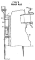
- In the case of a conventional upright vacuum cleaner, the dust collected by the cleaner can produce the condition illustrated in Figs. 6 and 7. When a certain amount of dust has been collected in a
paper bag 25 fixed to an end portion of anintake section 11 projecting into adust collection section 8, it becomes difficult to convey air from theintake section 11 into thepaper bag 25 to flow through thebag 25. On the other hand, the rotation of anelectric blower 9 at a certain number of revolutions per unit time causes air within the dust collectingsection 8 to be conveyed to the outside. Therefore, when the amount of dust collected increases to a certain amount, the internal pressure within the dust collectingsection 8 drops, and the pressure within apassage 35 defined by a member fixed to a position of thesection 8 by screws also drops. Amovable member 37 held in place by aspring 36 disposed in thepassage 35 remains stationary when the internal pressure is above a certain level. However, when the internal pressure becomes lower than this level, themovable member 37 moves compressing thespring 36, so as to allow an inflow of air (indicated by the arrows in Fig. 7) from the outside of thesection 8 to the inside thereof. This inflow of air prevents a vacuum being generated within the body of the cleaner, thereby preventing overheating of members such as a motor for the blower, and the resultant deformation of the resin material used in the cleaner. The movement of themovable member 37 allows the user to be informed of whether thepaper bag 25 is filled with dust or not. - Recently, a problem has been experienced with the above-described arrangement of the upright vacuum cleaner arising from an increase of fibrous dust, such as lint, due to changes in the living or working environment. Fibrous dust is, when received in the
paper bag 25, bulkier than dust such as earth and sand. Even when fibrous dust fills thepaper bag 25 and has indeed caused a drop in the internal pressure within the dust collectingsection 8, the internal pressure does not readily become low enough to cause movement of themovable member 37. This is because the fibrous dust filing thebag 25 has a lot of voids or spaces between its specks of dust. If the cleaner in this condition is used continuously, dust will be accumulated in theintake section 11 or in ahose 10. Eventually, the vacuum cleaner will not be able to suck any more dust. What is worse is that the dust-filled condition of the cleaner may not be discovered until thebag 25 is removed. - In the upright type vacuum cleaner as disclosed in Patent Abstracts of Japan vol. 13 No. 529 (C-658) (3877) , air sucked through a floor nozzle is led into a dust collecting bag located in a dust collecting section via a passageway such as a hose and, accordingly, dust is trapped in the bag while the air is filtered and cleaned air discharged. The bag when filled with dust can be removed from the dust collecting section on removal of a cover member. However, when the bag becomes filled with fibre-like dust such as cotton fibre, such dust can accumulate in the hose and nozzle without the user becoming aware until removal of the filled bag. If the vacuum cleaner is used in this condition, it can lead to damage through overheating.
- Some vacuum cleaners have a sensor employing a light-emitting element and a light-receiving element. A vacuum cleaner incorporating a dust sensor is disclosed in Patent Abstracts of Japan vol. 14 No. 63 (C-685) (4006) . The sensor consists of an LED and a phototransistor arranged to face each other in a suction port of the cleaner. These elements are usually protected by a transparent protective cover. However, when substances such as dry sand or earth, or moist fibre, earth or sand have adhered to the cover, the light of the sensor is blocked by the adhered substance, thereby causing a deterioration in the sensitivity of the sensor. In order to avoid this problem, it is necessary to clean the sensor frequently by, for instance, wiping it with a piece of cloth or the like. However, with this and conventional vacuum cleaners , it is impossible to clean the sensor easily because only one side of the sensor can be wiped and because the way in which the sensor becomes contaminated cannot be exactly established.
- The present invention has been developed in view of the above-mentioned problems of the prior art. A first object of the present invention is to provide a vacuum cleaner which allows a sensor portion to be easily cleaned, and which enables the user to know with ease the way in which the sensor portion has been contaminated.
- A second object of the present invention is to provide a vacuum cleaner having a sensor capable of uniformly detecting an amount of dust without being affected by variations in the intensity of the inflow of air from the hose.
- A third object of the present invention is to provide a vacuum cleaner having a sensor portion which does not easily become contaminated, thereby providing a more accurate sensor operation.
- A fourth object of the present invention is to provide a vacuum cleaner in which damage to the lower surface of a nozzle section is prevented.
- In order to achieve the first object, according to a first aspect of the present invention there is provided a vacuum cleaner comprising : a cleaner body; a dust collecting section provided in said body; an intake section projecting into said dust collecting section; a detecting means provided in said intake section; and a control section for controlling the output of an electric blower in accordance with a signal from said detecting means and for indicating the amount of dust on a display section, characterised in that there is a hose connecting a nozzle section rotatably disposed on a suction side of said cleaner body to the dust collecting section through said intake section, and said intake section comprises a first tabular member which is straight and a second tubular member bent at an angle of approximately 90° with respect to the first tubular member, said second tubular member having a lid which can be freely opened and closed.
- In order to achieve the second object, according to a second aspect of the present invention the light-emitting element and the light-receiving element are disposed at mutually opposing positions which are downstream of a bend of the intake section and which are substantially normal to the inflow of air from the hose.
- In order to achieve the third object, according to a third aspect of the present invention transparent members for protecting the light-emitting element and the light-receiving element are protruded from the inner wall of the associated tubular member of the intake section.
- In order to achieve the fourth object, according to a fourth aspect of the present invention the nozzle section has a lower surface made of a resin, the lower surface being provided with sheet-metal protector members at least on the portion thereof that is to be brought into contact with a floor surface.
- According to the first aspect directed to achieving the first object, when the sensor section is contaminated, it can be easily cleaned by either removing the paper bag or opening the lid provided on the second tubular member, that is, from either the front or back side of the intake section. Further, since light can enter from either side, the user can easily see the way in which the sensor section has been contaminated.
- According to the second aspect directed to achieving the second object, the light-emitting and light-receiving elements are provided at a location at which variations in the inflow of air caused by variations in the suction force are at their minimum. Therefore, the sensor section is capable of invariably detecting an amount of dust without being affected by variations in the intensity of the inflow of air from the hose.
- According to the third aspect directed to achieving the third object, the transparent members protecting the light-emitting and light-receiving elements are slightly protruded from the inner wall of the first tubular member. This allows some of the dust sucked up and flowing toward the dust-collecting section to impinge against the protecting members, thereby removing any dust adhering to the protecting members. Therefore, the sensor section is prevented from easily becoming contaminated.
- According to the fourth aspect directed to achieving the fourth object, the protector members provided at least on a portion where the lower surface of the nozzle section contacts a floor surface serve to increase the strength of the lower surface. This makes the lower surface of the nozzle section less vulnerable to damage by wear, etc.
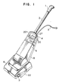
- Fig. 1 is a perspective view of a vacuum cleaner according to one embodiment of the present invention;
- Fig. 2 is a vertical sectional view of the vacuum cleaner of Fig. 1;
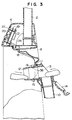
- Fig. 3 is a vertical sectional view of the essential parts of the vacuum cleaner of Fig. 1;
- Fig. 4 is an enlarged, front sectional view of some of the essential parts of the vacuum cleaner;
- Fig. 5 is a bottom view of a nozzle section of the vacuum cleaner of Fig. 1;
- Fig. 6 is a view schematically showing a conventional vacuum cleaner; and
- Fig. 7 is an enlarged sectional view of essential parts of the vacuum cleaner shown in Fig. 6.
- Referring to Figs. 1 and 2, a vacuum cleaner according to the present invention has a
handle 2 with a grip 1, and a power supply cord 3. A cleaner body includes adust collecting section 8 accommodating apaper bag 25, and two covers defining the front surface of the cleaner body, namely, anupper cover 4, and acover 5 which is detachably mounted thereon for thedust collecting section 8. - A nozzle section 6 having a
floor nozzle 7 provided therein is positioned on a suction side of the cleaner body and is rotatably mounted on a lower portion of the body. A rotatableelectric blower 9 is provided, and abelt 17 is provided for transmitting rotation of theblower 9 to thefloor nozzle 7. Ahose 10 connects the nozzle section 6 with the dust collectingsection 8. - An
intake section 11 projects into the dust collectingsection 8, and it comprises a firsttubular member 12 and a secondtubular member 13. The open end of thepaper bag 25 is detachably fixed to the firsttubular member 12. The secondtubular member 13 is connected to the proximal end of thehose 10. Themember 13 is bent at approximately 90°, and it has, on an outer wall thereof, alid 14 which can be freely closed (as shown in Fig. 2) and opened (as shown in Fig. 3). A detecting means 38 comprising a light-emittingelement 15 and a light-receivingelement 16 is provided in theintake section 11, and more specifically, in the firsttubular member 12. - As is best seen in Fig. 3, printed
circuit boards 19 withlight emitters 20, acontrol section 21, etc. mounted thereon are provided inside theupper cover 4, and are connected with the light-emitting and light-receivingelements leads 18. As shown in Fig. 4, transparent protectingmembers 26 are provided for the light-emitting and light-receivingelements leads 24, described later, are extended to thehandle 2. Adisplay section 27 is provided on theupper cover 4, as shown in Fig. 3. - As is best seen in Fig. 5 the nozzle section 6 includes a
reverse cover 22, and sheet-metal protector members 23 fixed to thereverse cover 22 by screws. - The vacuum cleaner having the above-described construction operates in the following manner. When an operation to clean a floor surface is started after the power supply cord 3 is connected to, for instance, an external power source, the
electric blower 9 starts to rotate. The shaft of theblower 9 causes, through thebelt 17, thefloor nozzle 7 of the nozzle section 6 to rotate so that dust on the floor surface is stirred up. Theblower 9 causes the air inside thedust collecting section 8 to be discharged to the outside so that the dust stirred up by thefloor nozzle 7 is passed through thehose 10 and theintake section 11, then collected into thepaper bag 25 within thedust collecting section 8. In this process, the light projected by the light-emittingelement 15 is blocked and prevented from reaching the light-receivingelement 16 each time a speck of dust crosses the light, whereby the detectingmeans 38 detects the volume of dust being collected. In accordance with a detected volume of dust, thecontrol section 21 on the printedcircuit boards 19 inside theupper cover 4 changes the output of theelectric blower 9. Also, the volume of the dust collected is displayed, bylight emitters 20, as one of various levels of dust-amount indications on thedisplay section 27. The flow of air is shown by the arrows in Fig. 2. - Referring to Fig. 3, if substances, such as dry earth or sand, or moist fibre or earth, adhere to the
members 26 protecting the light-emitting and light-receivingelements element 15 can be blocked by the adhered substances. In such cases, even when the dust crosses the projected light, the dust may not be correctly detected by detecting the size or the number of the specks of dust. It is necessary, therefore, that the transparent projectingmembers 26, which are provided on the inner wall of the firsttubular member 12 of theintake section 11, are wiped with a cloth or the like. For this purpose, the dustcollecting section cover 5 is opened, and thepaper bag 25 is removed. At this time, if thelid 14 provided on the secondtubular member 13 is also opened, the user can see exactly the way in which contamination has taken place, and moreover themembers 26 can be wiped not only via an opening of the firsttubular member 12 but also via an opening of the secondtubular member 13, as shown in Fig. 3. Because light can enter from the two openings in theintake section 11, the contamination of the sensor section can be observed more easily than in the case of conventional cleaners. A wiping operation may be performed during a cleaning operation when the sensitivity is found to be poor. If thelid 14 is opened in order to perform such wiping, the contaminating substances can be wiped off without removing thecover 5 and thepaper bag 25. - When the
paper bag 25 is filled with fibrous dust, with some of the dust reaching the light-emitting and light-receivingelements tubular member 12 of theintake section 11, the light projected by theelement 15 toward theelement 16 is blocked by said dust. Also, in this case, some of the dust moves in an uncertain manner under the suction force. Therefore, this condition can be identified as a condition in which a lot of dust is within the cleaner. Thecontrol section 21 operates in such a manner as to cause, if the detection of the same number of specks of dust, and the same size of dust, is repeated for a certain period of time, thelight emitters 21 to display an indication of a bag-filled condition, and stop theelectric blower 9, thereby informing the user of the condition. When thepaper bag 25 is filled with sucked up earth and sand, this condition can be determined in a similar manner because, in this case also, the light projected by theelement 15 does not reach the opposingelement 16. A similar indication is displayed when the protectingmembers 26 are soiled, thereby making it possible to positively inform the user of a condition requiring sensor cleaning. When thehose 10 is clogged with foreign matter, the light projected by theelement 15 continues to reach theother element 16, while dust continues to be undetected. Therefore , this condition can be determined and displayed in a similar manner. - The first
tubular member 12 of theintake section 11 is made of an electrically conductive material so that the light-emitting and light-receivingelements leads 24 are extended from the firsttubular member 12 to thehandle 2 which is made of a metal material. If the grip 1, screwed onto thehandle 2, is also made of an electrically conductive material, the static electricity generated in theintake section 11 is allowed to escape to the person holding the grip 1, thereby preventing erroneous operation of thecontrol section 21 which can be caused by static electricity. - Referring to Figs. 2 and 5, the
reverse cover 22 used on the lower surface of the nozzle section 6 is made of a resin material for the following reason. Conventionally, such a reverse cover has been a sheet-metal member. With this construction, although it is necessary that a wide bristle portion is provided on thefloor nozzle 7 in order to have thenozzle 7 cover a large area of a floor surface, it is sometimes impossible to form, in a sheet-metal member, a narrow portion permitting a wide bristle portion. However, forming thecover 22 with only a resin material involves the risk of friction occurring between the resin cover and the floor surface as well as the risk of the resin cover being abraded or worn by metal members such as screws. In order to avoid these risks, a certain portion of the lower surface of the nozzle section 6 which contacts the floor surface is formed by the sheet-metal protector members 23. - Referring to Fig. 4, the light-emitting
element 15 and the light-receivingelement 16 are mounted on printedcircuit boards hose 10, indicated by the broken lines in Fig. 4, extends from the nozzle section 6 to theintake section 11, and air flows through thehose 10 and thesection 11, as indicated by the broken-line arrow and the solid-line arrow, respectively. The secondtubular member 13, which is bent at approximately 90° as viewed from a side (as shown in Fig. 2), is connected with thehose 10 heading from an obliquely downward position to the intake section 11 (as shown in Fig. 4). Let us now consider the flow of air through these members. It is considered that air flowing in thehose 10 is advancing at the same speed throughout thehose 10. When the air flows into the firsttubular member 12 of theintake section 11 after the air flow has been diverted by approximately 90°, the flow of air is changed in various ways. When the suction force is strong, the air collides against the inner wall of the secondtubular member 13 bent approximately normal, then advances while forming a turbulent flow, as indicated by the arrow A in Fig. 2. When the suction force is weak, there is not much turbulence, and the air flows along the bend of the secondtubular member 13 into the firsttubular member 12, as indicated by the arrow B. Thus, the flow of air is varied by variations in the suction force. The variations in the air flow are considered to occur at the maximum level in the direction in which thehose 10 is directed into the secondtubular member 13 of theintake section 11, that is, the direction indicated by the broken-line arrow in Fig. 4. Therefore, if the light-emitting and light-receivingelements detection elements - The
transparent members 26 for protecting the light-emitting and light-receivingelements tubular member 12 of theintake section 11 for the following reason. Even when dust such as powdery dust or fibre wet with water adheres to the protectingmembers 26, this arrangement of themembers 26 allows fibrous dust such as lint sucked up under the suction force of the cleaner to impinge against the protectingmembers 26, thereby removing the adhered substances. However, if the dimension by which themembers 26 are protruded exceeds the value a shown in Fig. 4, this may lead to clogging with foreign matter. The allowable upper limit of protrusion is considered to be 1 mm. Dimensions equal to or less than 1 mm are advantageous in that, even if hard substances, such as a piece of metal, have been sucked up, the dust is not believed to cause serious damage although it strikes an edge of the protruded portion. There is little possibility of metal dust, which is relatively heavy impinging against the protruded portions because it is believed that, when such dust advances in thecurved hose 10, the dust tends to move radially inwardly toward the axial centre of thehose 10. However, should protectingmembers 26 be formed therein with recessed surfaces, it would be disadvantageous in that dust may be trapped in the recesses. The trapped dust may not be removed from themembers 26 even when fibrous dust, such as lint, is sucked up later. Removing the trapped dust by a manual operation can also be difficult. - As described above, the present invention provides the following effects:
- (1) A vacuum cleaner has a dust collecting section in the cleaner body, an intake section projecting into the dust collecting section, a hose connecting the nozzle section rotatably disposed on the suction side of the cleaner body with the dust collecting section through the intake section, a detecting means for detecting dust flowing in the hose, and a control section for controlling the output of an electric blower in accordance with a signal from a detecting means and for indicating the amount of dust on a display section. The detecting means comprises a light-emitting element and a light-receiving element which are provided at mutually opposing positions of the intake section. The intake section comprises a first tubular member which is straight and a second tubular member which is bent at an angle of approximately 90°, the second tubular member having a lid which can be freely opened and closed. When the sensor section is contaminated, it can be easily cleaned by either removing the paper bag or opening the openable lid on the second tubular member, that is, from either the front or back side of the intake section. Further, since light can enter from either side, the user can easily see the way in which the sensor section has been contaminated.
- (2) With the construction under Item (1), the light-emitting element and the light-receiving element are disposed at mutually opposing positions which are downstream of the bend, and which are substantially normal to the inflow of air from the hose. Since these elements are provided at a location at which variations in the inflow of air caused by variations in the suction force are at their minimum, the sensor section is capable of uniformly detecting an amount of dust without being affected by variations in the intensity of the inflow of air from the hose.
- (3) The light-emitting and light-receiving elements are protected by transparent projecting members which are protruded from the inner wall of the associated tubular member of the intake section. This allows some of the dust sucked up and flowing toward the dust-collecting section to strike against the protecting members, thereby removing any dust adhering to the protecting members. Therefore, the sensor section is prevented from becoming easily contaminated.
- (4) The nozzle section has a lower surface made of a resin and provided with sheet-metal protector members at least on a portion thereof that is to be brought into contact with a floor surface. This makes the lower surface of the nozzle section less vulnerable to damage by wear, etc.
Claims (5)
- A vacuum cleaner comprising : a cleaner body; a dust collecting section (8) provided in said body; an intake section (11) projecting into said dust collecting section (8); a detecting means (38) provided in said intake section (11); and a control section (21) for controlling the output of an electric blower (9) in accordance with a signal from said detecting means (38) and for indicating the amount of dust on a display section (27), characterised in that there is a hose (10) connecting a nozzle section (6) rotatably disposed on a suction side of said cleaner body to the dust collecting section (8) through said intake section (11), and said intake section comprises a first tubular member (12) which is straight and a second tubular member (13) bent at an angle of approximately 90° with respect to the first tubular member (12), said second tubular member (13) having a lid (14) which can be freely opened and closed.
- A vacuum cleaner according to claim 1, characterised in that said detecting means (38) comprises a light-emitting element (15) and a light-receiving element (16) which are provided at mutually opposing positions in said intake section.
- A vacuum cleaner according to claim 2, characterised in that said intake section (11) defines a bent intake passage, said light-emitting element (15) and said light-receiving element (16) being disposed at mutually opposing positions which are downstream of the bend of said intake section (11), and which are substantially normal to the inflow of air from said hose (10).
- A vacuum cleaner according to any of claims 1 to 3, characterised in that it includes transparent members (26) for protecting said light-emitting element (15) and said light-receiving element (16), the transparent protecting members (26) being protruded from an inner wall of the associated tubular member (12, 13) of said intake section (11).
- A vacuum cleaner according to any of claims 1 to 4, characterised in that said nozzle section (6) has a lower surface made of a resin, the lower surface being provided with sheet-metal protector members (23) at least on a portion thereof that is to be brought into contact with a floor surface.
Applications Claiming Priority (2)
| Application Number | Priority Date | Filing Date | Title |
|---|---|---|---|
| JP41771/90 | 1990-02-22 | ||
| JP04177190A JP3149430B2 (en) | 1990-02-22 | 1990-02-22 | Upright vacuum cleaner |
Publications (2)
| Publication Number | Publication Date |
|---|---|
| EP0443845A1 EP0443845A1 (en) | 1991-08-28 |
| EP0443845B1 true EP0443845B1 (en) | 1994-06-08 |
Family
ID=12617653
Family Applications (1)
| Application Number | Title | Priority Date | Filing Date |
|---|---|---|---|
| EP91301369A Expired - Lifetime EP0443845B1 (en) | 1990-02-22 | 1991-02-20 | Vacuum cleaner |
Country Status (6)
| Country | Link |
|---|---|
| US (1) | US5144714A (en) |
| EP (1) | EP0443845B1 (en) |
| JP (1) | JP3149430B2 (en) |
| CA (1) | CA2036826C (en) |
| DE (1) | DE69102304T2 (en) |
| ES (1) | ES2055526T3 (en) |
Families Citing this family (46)
| Publication number | Priority date | Publication date | Assignee | Title |
|---|---|---|---|---|
| US5448794A (en) * | 1993-09-16 | 1995-09-12 | Electrolux Corporation | Corded handheld vacuum cleaner |
| US5507067A (en) * | 1994-05-12 | 1996-04-16 | Newtronics Pty Ltd. | Electronic vacuum cleaner control system |
| KR200155821Y1 (en) * | 1997-05-12 | 1999-10-01 | 최진호 | Remote control vacuum cleaner |
| US6023814A (en) * | 1997-09-15 | 2000-02-15 | Imamura; Nobuo | Vacuum cleaner |
| US8412377B2 (en) | 2000-01-24 | 2013-04-02 | Irobot Corporation | Obstacle following sensor scheme for a mobile robot |
| US8788092B2 (en) | 2000-01-24 | 2014-07-22 | Irobot Corporation | Obstacle following sensor scheme for a mobile robot |
| CN1225222C (en) | 2000-01-31 | 2005-11-02 | 松下电器产业株式会社 | electric vacuum cleaner |
| US6956348B2 (en) | 2004-01-28 | 2005-10-18 | Irobot Corporation | Debris sensor for cleaning apparatus |
| WO2002011599A1 (en) | 2000-08-07 | 2002-02-14 | Arçelik A.S. | A cleaning device for a sensor and a vacuum cleaner comprising such a cleaning device |
| US6812847B1 (en) * | 2000-08-25 | 2004-11-02 | The Hoover Company | Moisture indicator for wet pick-up suction cleaner |
| US6690134B1 (en) | 2001-01-24 | 2004-02-10 | Irobot Corporation | Method and system for robot localization and confinement |
| US7571511B2 (en) | 2002-01-03 | 2009-08-11 | Irobot Corporation | Autonomous floor-cleaning robot |
| US7429843B2 (en) | 2001-06-12 | 2008-09-30 | Irobot Corporation | Method and system for multi-mode coverage for an autonomous robot |
| US8396592B2 (en) | 2001-06-12 | 2013-03-12 | Irobot Corporation | Method and system for multi-mode coverage for an autonomous robot |
| US9128486B2 (en) | 2002-01-24 | 2015-09-08 | Irobot Corporation | Navigational control system for a robotic device |
| US8428778B2 (en) | 2002-09-13 | 2013-04-23 | Irobot Corporation | Navigational control system for a robotic device |
| US8386081B2 (en) | 2002-09-13 | 2013-02-26 | Irobot Corporation | Navigational control system for a robotic device |
| KR20050026163A (en) * | 2003-09-09 | 2005-03-15 | 삼성광주전자 주식회사 | Apparatus for protecting motor-overload of vaccum cleaner |
| US7332890B2 (en) | 2004-01-21 | 2008-02-19 | Irobot Corporation | Autonomous robot auto-docking and energy management systems and methods |
| DE112005000738T5 (en) | 2004-03-29 | 2007-04-26 | Evolution Robotics, Inc., Pasadena | Method and device for determining position using reflected light sources |
| KR101214723B1 (en) | 2004-06-24 | 2012-12-24 | 아이로보트 코퍼레이션 | Remote control scheduler and method for autonomous robotic device |
| US7706917B1 (en) | 2004-07-07 | 2010-04-27 | Irobot Corporation | Celestial navigation system for an autonomous robot |
| US8972052B2 (en) | 2004-07-07 | 2015-03-03 | Irobot Corporation | Celestial navigation system for an autonomous vehicle |
| US7620476B2 (en) | 2005-02-18 | 2009-11-17 | Irobot Corporation | Autonomous surface cleaning robot for dry cleaning |
| ES2346343T3 (en) | 2005-02-18 | 2010-10-14 | Irobot Corporation | AUTONOMOUS SURFACE CLEANING ROBOT FOR DRY AND WET CLEANING. |
| US8392021B2 (en) | 2005-02-18 | 2013-03-05 | Irobot Corporation | Autonomous surface cleaning robot for wet cleaning |
| US8930023B2 (en) | 2009-11-06 | 2015-01-06 | Irobot Corporation | Localization by learning of wave-signal distributions |
| US20060272122A1 (en) * | 2005-06-07 | 2006-12-07 | Dennis Butler | Vacuum brushroll edge cleaner |
| KR101300492B1 (en) | 2005-12-02 | 2013-09-02 | 아이로보트 코퍼레이션 | Coverage robot mobility |
| EP2816434A3 (en) | 2005-12-02 | 2015-01-28 | iRobot Corporation | Autonomous coverage robot |
| EP2533120B1 (en) | 2005-12-02 | 2019-01-16 | iRobot Corporation | Robot system |
| US8584305B2 (en) | 2005-12-02 | 2013-11-19 | Irobot Corporation | Modular robot |
| EP2829939B1 (en) | 2005-12-02 | 2019-11-13 | iRobot Corporation | Autonomous coverage robot navigation system |
| US8528157B2 (en) | 2006-05-19 | 2013-09-10 | Irobot Corporation | Coverage robots and associated cleaning bins |
| US8417383B2 (en) | 2006-05-31 | 2013-04-09 | Irobot Corporation | Detecting robot stasis |
| ES2559128T3 (en) | 2007-05-09 | 2016-02-10 | Irobot Corporation | Autonomous compact covering robot |
| US20100236013A1 (en) * | 2009-03-17 | 2010-09-23 | Electrolux Home Care Products, Inc. | Vacuum Cleaner Sensor |
| KR101497197B1 (en) | 2010-02-16 | 2015-02-27 | 아이로보트 코퍼레이션 | Vacuum brush |
| JP5620127B2 (en) * | 2010-03-12 | 2014-11-05 | 株式会社東芝 | Electric vacuum cleaner |
| SE534963C2 (en) * | 2010-06-29 | 2012-02-28 | Electrolux Ab | Dust indicator for a vacuum cleaner |
| SE534962C2 (en) | 2010-06-29 | 2012-02-28 | Electrolux Ab | Dust detection system for a vacuum cleaner |
| WO2012092565A1 (en) * | 2010-12-30 | 2012-07-05 | Irobot Corporation | Debris monitoring |
| EP2916705B1 (en) | 2012-11-09 | 2020-06-03 | Aktiebolaget Electrolux | Cyclone dust separator arrangement, cyclone dust separator and cyclone vacuum cleaner |
| WO2017136848A1 (en) * | 2016-02-04 | 2017-08-10 | Haws Corporation | Integrated water detection sensor |
| CN110179399B (en) * | 2019-06-28 | 2023-11-28 | 小狗电器互联网科技(北京)股份有限公司 | Dust channel for dust collector and dust collector |
| CN112603197B (en) * | 2020-12-10 | 2022-05-10 | 江苏美的清洁电器股份有限公司 | Floor brush and control method of floor brush |
Family Cites Families (15)
| Publication number | Priority date | Publication date | Assignee | Title |
|---|---|---|---|---|
| US3199138A (en) * | 1963-04-22 | 1965-08-10 | Whirlpool Co | Cleaner |
| NL7212108A (en) * | 1972-09-06 | 1974-03-08 | ||
| US4199839A (en) * | 1978-10-12 | 1980-04-29 | Health-Mor, Inc. | Suction cleaner power nozzle construction |
| DE2900433C2 (en) * | 1979-01-08 | 1981-03-12 | Vorwerk & Co Interholding Gmbh, 5600 Wuppertal | Optical fill level indicator for the dust bag of a vacuum cleaner |
| DE3431164A1 (en) * | 1984-02-08 | 1985-08-14 | Gerhard 7262 Althengstett Kurz | VACUUM CLEANER |
| DE3431175C2 (en) * | 1984-02-08 | 1986-01-09 | Gerhard 7262 Althengstett Kurz | Protective device for dust collection devices |
| DE3534621A1 (en) * | 1985-09-28 | 1987-04-02 | Interlava Ag | VACUUM CLEANER |
| EP0231419A1 (en) * | 1986-02-05 | 1987-08-12 | Interlava AG | Indicating and function controlling optical unit for a vacuum cleaner |
| JPS63246125A (en) * | 1987-04-02 | 1988-10-13 | 松下電器産業株式会社 | vacuum cleaner |
| DE3803824A1 (en) * | 1988-02-09 | 1989-08-17 | Gerhard Kurz | INSTALLATION DEVICE FOR SENSORS AND SENSORS |
| JPH01214324A (en) * | 1988-02-23 | 1989-08-28 | Matsushita Electric Ind Co Ltd | Upright type electric cleaner |
| JPH01285236A (en) * | 1988-05-13 | 1989-11-16 | Matsushita Electric Ind Co Ltd | Dust detector for vacuum cleaner |
| JPH01299525A (en) * | 1988-05-26 | 1989-12-04 | Matsushita Electric Ind Co Ltd | Floor nozzle for vacuum cleaner |
| KR910006887B1 (en) * | 1988-06-15 | 1991-09-10 | 마쯔시다덴기산교 가부시기가이샤 | Garbage Detection Device of Electric Cleaner |
| JP2547630B2 (en) * | 1988-12-19 | 1996-10-23 | 三洋電機株式会社 | Electric vacuum cleaner |
-
1990
- 1990-02-22 JP JP04177190A patent/JP3149430B2/en not_active Expired - Fee Related
-
1991
- 1991-02-19 US US07/657,059 patent/US5144714A/en not_active Expired - Lifetime
- 1991-02-20 ES ES91301369T patent/ES2055526T3/en not_active Expired - Lifetime
- 1991-02-20 EP EP91301369A patent/EP0443845B1/en not_active Expired - Lifetime
- 1991-02-20 DE DE69102304T patent/DE69102304T2/en not_active Expired - Fee Related
- 1991-02-21 CA CA002036826A patent/CA2036826C/en not_active Expired - Lifetime
Also Published As
| Publication number | Publication date |
|---|---|
| JPH03244420A (en) | 1991-10-31 |
| ES2055526T3 (en) | 1994-08-16 |
| DE69102304D1 (en) | 1994-07-14 |
| CA2036826A1 (en) | 1991-08-23 |
| JP3149430B2 (en) | 2001-03-26 |
| EP0443845A1 (en) | 1991-08-28 |
| CA2036826C (en) | 2000-03-28 |
| US5144714A (en) | 1992-09-08 |
| DE69102304T2 (en) | 1994-12-08 |
Similar Documents
| Publication | Publication Date | Title |
|---|---|---|
| US5144714A (en) | Vacuum cleaner | |
| EP4274456B1 (en) | Handheld vacuum cleaner and vacuum cleaner brush assembly | |
| KR101223478B1 (en) | Apparatus sensing the engagement of a dust tank for a robot-cleaner | |
| EP2030543B1 (en) | Stick type vacuum cleaner | |
| EP2417893B1 (en) | Robot cleaner | |
| WO2009154319A1 (en) | Air flowing-sensing unit and cleaning apparatus having the same | |
| KR102366802B1 (en) | Garment cleaner | |
| CN119421653A (en) | Vacuum cleaners with floor protection operating mode | |
| US20070012001A1 (en) | Dust collecting unit for vacuum cleaner | |
| JPH06105764A (en) | Upright type vacuum cleaner | |
| CN217090595U (en) | Liquid storage tank | |
| JP2007068684A (en) | Electric vacuum cleaner | |
| KR200164817Y1 (en) | Device for checking tube choke of vacuum cleaner | |
| JP6851182B2 (en) | Vacuum cleaner | |
| JPH05253156A (en) | Upright type cleaner | |
| KR102313294B1 (en) | Cleaner | |
| KR200164818Y1 (en) | Device for checking tube choke of vacuum cleaner | |
| EP1313395B1 (en) | A cleaning device for a sensor and a vacuum cleaner comprising such a cleaning device | |
| US20240292989A1 (en) | Vacuum cleaner having adaptive dirt identification and method for operating the vacuum cleaner | |
| CN219048268U (en) | Cleaning base station | |
| KR930007481Y1 (en) | Vacuum cleaner dirt suction device | |
| KR200182561Y1 (en) | Mounting structure of dust perceiving sensor for upright vacuum cleaner | |
| JPH03186238A (en) | upright vacuum cleaner | |
| KR20090079147A (en) | Cyclone dust collector and cleaner having same | |
| JPH04343829A (en) | vacuum cleaner |
Legal Events
| Date | Code | Title | Description |
|---|---|---|---|
| PUAI | Public reference made under article 153(3) epc to a published international application that has entered the european phase |
Free format text: ORIGINAL CODE: 0009012 |
|
| AK | Designated contracting states |
Kind code of ref document: A1 Designated state(s): DE ES FR GB |
|
| 17P | Request for examination filed |
Effective date: 19911016 |
|
| 17Q | First examination report despatched |
Effective date: 19930201 |
|
| GRAA | (expected) grant |
Free format text: ORIGINAL CODE: 0009210 |
|
| AK | Designated contracting states |
Kind code of ref document: B1 Designated state(s): DE ES FR GB |
|
| REF | Corresponds to: |
Ref document number: 69102304 Country of ref document: DE Date of ref document: 19940714 |
|
| REG | Reference to a national code |
Ref country code: ES Ref legal event code: FG2A Ref document number: 2055526 Country of ref document: ES Kind code of ref document: T3 |
|
| ET | Fr: translation filed | ||
| PLBE | No opposition filed within time limit |
Free format text: ORIGINAL CODE: 0009261 |
|
| STAA | Information on the status of an ep patent application or granted ep patent |
Free format text: STATUS: NO OPPOSITION FILED WITHIN TIME LIMIT |
|
| 26N | No opposition filed | ||
| REG | Reference to a national code |
Ref country code: GB Ref legal event code: IF02 |
|
| PGFP | Annual fee paid to national office [announced via postgrant information from national office to epo] |
Ref country code: ES Payment date: 20070228 Year of fee payment: 17 |
|
| PGFP | Annual fee paid to national office [announced via postgrant information from national office to epo] |
Ref country code: FR Payment date: 20070208 Year of fee payment: 17 |
|
| REG | Reference to a national code |
Ref country code: FR Ref legal event code: ST Effective date: 20081031 |
|
| PG25 | Lapsed in a contracting state [announced via postgrant information from national office to epo] |
Ref country code: FR Free format text: LAPSE BECAUSE OF NON-PAYMENT OF DUE FEES Effective date: 20080229 |
|
| REG | Reference to a national code |
Ref country code: ES Ref legal event code: FD2A Effective date: 20080221 |
|
| PGFP | Annual fee paid to national office [announced via postgrant information from national office to epo] |
Ref country code: DE Payment date: 20090213 Year of fee payment: 19 |
|
| PGFP | Annual fee paid to national office [announced via postgrant information from national office to epo] |
Ref country code: GB Payment date: 20090217 Year of fee payment: 19 |
|
| PG25 | Lapsed in a contracting state [announced via postgrant information from national office to epo] |
Ref country code: ES Free format text: LAPSE BECAUSE OF NON-PAYMENT OF DUE FEES Effective date: 20080221 |
|
| GBPC | Gb: european patent ceased through non-payment of renewal fee |
Effective date: 20100220 |
|
| PG25 | Lapsed in a contracting state [announced via postgrant information from national office to epo] |
Ref country code: DE Free format text: LAPSE BECAUSE OF NON-PAYMENT OF DUE FEES Effective date: 20100901 |
|
| PG25 | Lapsed in a contracting state [announced via postgrant information from national office to epo] |
Ref country code: GB Free format text: LAPSE BECAUSE OF NON-PAYMENT OF DUE FEES Effective date: 20100220 |