EP0443889A1 - Temperaturregelungsvorrichtung für ein schweres Teil - Google Patents
Temperaturregelungsvorrichtung für ein schweres Teil Download PDFInfo
- Publication number
- EP0443889A1 EP0443889A1 EP91400149A EP91400149A EP0443889A1 EP 0443889 A1 EP0443889 A1 EP 0443889A1 EP 91400149 A EP91400149 A EP 91400149A EP 91400149 A EP91400149 A EP 91400149A EP 0443889 A1 EP0443889 A1 EP 0443889A1
- Authority
- EP
- European Patent Office
- Prior art keywords
- enclosure
- temperature
- cavity
- solenoid valve
- liquid
- Prior art date
- Legal status (The legal status is an assumption and is not a legal conclusion. Google has not performed a legal analysis and makes no representation as to the accuracy of the status listed.)
- Withdrawn
Links
Images


Classifications
-
- B—PERFORMING OPERATIONS; TRANSPORTING
- B30—PRESSES
- B30B—PRESSES IN GENERAL
- B30B15/00—Details of, or accessories for, presses; Auxiliary measures in connection with pressing
- B30B15/06—Platens or press rams
- B30B15/062—Press plates
- B30B15/064—Press plates with heating or cooling means
-
- G—PHYSICS
- G05—CONTROLLING; REGULATING
- G05D—SYSTEMS FOR CONTROLLING OR REGULATING NON-ELECTRIC VARIABLES
- G05D23/00—Control of temperature
- G05D23/19—Control of temperature characterised by the use of electric means
- G05D23/1919—Control of temperature characterised by the use of electric means characterised by the type of controller
Definitions
- the present invention relates to a device for regulating the temperature of solid parts, in particular press plates.
- the plates Given the clamping forces and the intrinsic resistance of the blank, it is necessary for the plates to be solid so as to undergo no deformation or at least only deformations compatible with the tolerances required for the part.
- a network of pipes starts from this steam generating station and supplies each of the presses individually. This network is fixed on the ceiling or on the floor.
- this steam heating is not flexible to use because it is necessary to start up the power plant regardless of the number of presses used and any "geographic" movement of a press within the workshop. or the factory also requires a modification of the distribution network.
- the boiler for steam production must also be calculated for a specific number of presses. Given the fact that the number of presses can change, users generally provide oversized boilers. This leads to investments greater than the needs and if the increase is sufficient it may be necessary to change the entire boiler, which again represents additional costs.
- thermofluid such as oil for example which is circulated in the plates.
- thermofluids cover important temperature ranges because lower than 100 ° C if necessary, but also several hundred degrees without working under pressure.
- the essential advantage which the steam procured namely the self-regulation, is suppressed taking into account the fact that the exchange of calories between the thermofluid and the plate takes place according to a very complex distribution impossible to determine point per point.
- the oil oxidizes as it is used and it is necessary to plan a regular replacement following a periodicity of a few months, six months generally.
- thermofluids in particular oil, are not liquids which are pleasant to handle.
- This solution also has no flexibility of use since it has the same drawbacks as steam heating when moving the machine, when choosing the boiler and its sizing, or during operation.
- a third solution is to heat the press platens using heating pencils electric.
- the press plates are provided with bores into which are introduced heating rods themselves connected to a source of electrical energy.
- This solution has the advantage of being very clean, of requiring no central heating and the machines can be increased in number or simply moved without any difficulty.
- thermofluid a temperature control device which combines the advantages of self-regulation provided by steam heating, the wide range of use and temperature variation presented by heating by thermofluid and the flexibility and cleanliness of electric heating which does not require any centralized production, no network of pipes but a simple electrical connection.
- the object of the present invention is to provide a device for regulating the temperature of a solid part which provides self-regulation at a fixed and adjustable temperature of the part, which is attached to one or a few machines, which can be moved with that -this, which can be started and stopped in a simple way, which presents no risk of ignition, whose operating cost is low, which has high temperature regulation accuracy.
- the device for regulating the temperature of a solid part provided with at least one cavity comprises an enclosed enclosure, partially filled with a heat-transfer liquid, connections between this cavity and the enclosure, means for heating the heat-transfer liquid of at least sufficient power to bring this liquid to a boil and is characterized in that it comprises automatic means for purging the air contained in the circuit so that the entire circuit works under vacuum.
- the closed enclosure is connected in a closed circuit to the cavity by supply and return conduits, the purge means being arranged at the outlet of the cavity.
- the purging means comprise a solenoid valve controlled by an automaton also connected to at least two temperature measurement probes, close to the solenoid valve on the one hand and in the enclosure on the other hand.
- the automaton is programmed to command the opening of the solenoid valve for a preset time when the two measured temperatures are different and this difference is greater than a given deviation value.
- the automatic device also includes means for varying the temperature setpoint at the outlet of the room so as to vary the temperature setpoint in the enclosure and successively in the cavity.
- the device also comprises means for regulating the level of liquid in the enclosure.
- the solenoid valve of the draining means is connected to a condensate recovery tank so as to allow recycling of the heat transfer liquid.
- the device is characterized in that the tank is arranged at a level located above the entry and exit points of the cavity in that it comprises a second enclosure disposed at the outlet of the cavity and interposed on the return pipe and a pump interposed between this second enclosure and the main enclosure.
- the device applies to the temperature regulation of a press plate, the heat transfer fluid being water.
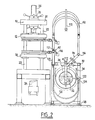
- FIG. 1 shows a press 10, with two plates, one 12, respectively fixed and adjustable in height and the other 14 movable, the device 16 for regulation according to the invention and the electrical control console 18.
- the press 10 comprises in known manner a frame 20, comprising guide columns 22 on which the plates 12 and 14 move.
- the fixed plate 12 is adjustable in height by means of a screw 24 and a nut 26 while the plate 14 is driven in translation on the columns 22 by means of a jack 28 disposed in the lower part of the press.
- the regulating device 16 comprises a frame 30 supporting a closed enclosure 32, stirrups 34 a tab 36 integral with the frame.
- the frame rests on the ground via feet 38.
- the device also includes automatic means for purging 40 of the fluid connections 42 between the press plates and the enclosure 32 as well as heating means 44 for the enclosure.
- the enclosure 32 shown in FIG. 3 comprises a tank 46 hermetically closed by a cover 48 connected to the tank by an annular flange 50 with a seal 52 interposed between tank and cover and tightening bolts 54.
- the tank 46 and its cover are surrounded by a cover 56 and an insulating material 58.
- the cover 56 is fixed to the tank by means of the spacers 60 and the bolts 62.
- the flange 34 is fixed by the bolts 64 to the frame and directly supports the cover to which it is fixed by lugs 66 locked by pins 68.
- the tank 46 is further provided with a support 70 which cooperates with a bore in the tab 36 to maintain the tank relative to the frame.
- the tank 32 comprises an evacuation tap 72.
- This tap 72 includes a tube 74 which passes through the wall of the tank 46 to immerse at its lower part 76 in the heat transfer liquid 33 and which emerges at its upper part 78, this upper end receiving a level 80 detector.
- the tube 74 is closed at the end of its lower part 76 by a bottom plate 82 provided with a nozzle 84. Furthermore, the tube 74 comprises a window 86 formed in the free space above the heat transfer fluid 33.
- the level detector 80 comprises two minimum and maximum level pick-up tubes 90 and 92.
- a connector 94 is provided which connects the flexible tubes of the fluid connections. 42 at the discharge nozzle 72.
- a safety valve 96 of known type is also required, which is required on any device working under pressure.
- the tank also comprises an introductory tap 98 opening below the level of heat transfer liquid 33 and connected to the return duct 43.
- a drain tap 100 is provided at the bottom of the tank 46, at a low point so as to be able to completely empty the heat transfer liquid if necessary.
- the cover also includes a tap 102 to allow the passage of a temperature probe 104 opening above the free surface of the heat transfer fluid 33.
- the probe 104 is connected by a cable 106 to a control automaton (not shown) as will be explained later.
- the heating means 44 of the enclosure 32 include thermowells 108 fixed in the cover in which electrical heating resistors 110 are arranged.
- the fluid connections 42 between the connector 94 and the plates are produced by means of flexible supply conduits held by a support 112 so as to facilitate the displacement of the pipes during movements of the plates without causing their deterioration.
- two independent supply conduits are provided. It suffices to provide a splitting 114 at the end of the connector 94 as shown in FIGS. 1 and 2.
- the connections between the flexible conduits and the plates are made in a known manner. Indeed, the trays are originally fitted with an inlet and an outlet as well as an internal cavity.
- the purge means 40 are arranged which comprise a solenoid valve 116 and a temperature measurement probe 117 and disposed at the top of a rigid tube 118 itself connected to tubes flexible 120 constituting the condensate return conduits.
- the end of these flexible tubes is fixed to the insertion nozzle which comprises a manifold 122 as well as non-return valves 124 upstream of the manifold and arranged at the end of the tubes 120.
- the level detector 80 acts through the automaton, on an electrically controlled solenoid valve 125 and disposed between the manifold 122 and the reservoir 124 which contains heat transfer liquid reserve.
- the closed enclosure comprises water and air, the entire circuit being at ambient temperature.
- the heating resistors 110 are supplied with electrical energy which causes the temperature of the heat-transfer liquid 33 to rise until it boils.
- the rise in pressure causes the vapor to move from the closed enclosure to the plates in the cavity of which it circulates, to exit, after condensation, in the rigid tubes 118 and through the flexible tubes 120 as far as the tank 46.
- the water level 33 is always disposed below the opening 86 in the tube 74 of the evacuation nozzle 72 so that the level detector 80 is not disturbed by sudden variations in level or by boiling since the level is measured in the tube 74 and the nozzle 84 attenuates any sudden variation in level.
- the probe 104 detects a temperature T1 in the enclosure which is different from the temperature T2 measured near the solenoid valves 116.
- the solenoid valve 116 is then opened by the automatic device which detects a temperature difference for a predetermined duration. So a certain volume of air, accumulated in the tube 118 in its upper part, is evacuated through the solenoid valve 116.
- the lower part of the flexible tube is filled with water of condensation and the air entrained by the vapor accumulates in this tube 118.
- the press plates must be brought to a given temperature T3 which will be called the set temperature.
- This setpoint temperature value is recorded in the PLC which constantly compares the temperature T2 and the setpoint temperature T3.
- T3 When switching on it is necessary to provide a temperature T3 higher than the boiling point of the heat transfer liquid 33 at atmospheric pressure. Thereafter after the air vacuum has been made, T3 must be higher than the boiling temperature under vacuum.
- the automaton also compares the temperatures T2 and T1 so as to periodically cause the opening of the solenoid valve 116 as long as the temperatures T1 and T2 are different and this difference is greater than a given deviation value. Any difference in temperature between these two probes indicates the presence of air in the circuit.
- the device is ready to operate for temperatures below 100 ° C, between 60 and 70 ° C, up to temperatures of 200 ° C as required.
- This possibility of working at temperatures below 100 ° is due to the fact that the circuit works under vacuum and that the point boiling liquid, in this case water, is lowered.
- the rise in temperature it suffices to supply the calories necessary for the heat-transfer fluid, which also increases the pressure in the sealed circuit.
- the various parts of the circuit and the various fittings must be provided accordingly so as to be able to withstand pressures up to 20 bars and depressions.
- the evacuation via the solenoid valve 116 causes very small losses of liquid which accumulated can nevertheless cause a drop in the level of the liquid 33 in the tank 46, this difference being recorded by the level detector 80.
- the level detector causes the opening of the solenoid valve of the reservoir 124 so as to admit a supplement of heat transfer liquid in the reservoir 46 via the manifold 122. This operation is only carried out at low temperature when the enclosure is under vacuum .
- a reservoir 130 makes it possible to collect the liquid discharged through the solenoid valve when it condenses.
- This tank is liquid tight, but it is provided with a vent so that it is always maintained at atmospheric pressure.
- Such a tank is connected by a pipe 132 to the closed enclosure 32, more particularly to the tank 46.
- a buffer tank 134 and two valves 136 and 138 are interposed on this pipe 132 so as to be able to reintroduce the heat transfer liquid accumulated in the tank 130 in the tank 46 by alternative opening of the valves 136 and 138.
- auxiliary tank 124 can be eliminated in favor of the recycling circuit.
- the electrically controlled valves 136 and 138 are controlled by the automaton so as to reinject heat transfer liquid as soon as the level detector 80 registers a sufficient level drop.
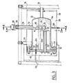
- FIG. 8 An alternative arrangement of the various components is shown schematically in FIG. 8.
- the closed enclosure 32 is arranged in the upper part above the press plates. In this case, it is provided a second pressure-resistant enclosure 200. In order to compensate for the level difference, a level detector 210 with minimum and maximum must be installed on this enclosure. In this embodiment, the second enclosure can be common to the two plates.
- a low-power lift pump 220 must be interposed.
- FIG 9 there is shown a variant of tank 346 with vertical longitudinal axis which is monolithic without cover or bolts.
- the steam outlet 394 is located in the upper part and the evacuation tap 372 is identical to that of the preferred embodiment.
- the main advantage lies in saving space and eliminating removable flange-cover connection, thereby reducing costs.
- the thimbles 308 are also oriented parallel to the longitudinal axis of the tank. There is also a 302 tap for the temperature measurement probe.
- the liquid used is water. However, it is necessary to provide a composition of water whose pH and any additives are compatible with the materials constituting the elements of the device according to the invention.
- this term is not necessarily an industrial programmable automaton but can consist of a simple logic circuit with regulators, and other timers.
- regulators are commercially available under the brand EUROTHERM, in particular the 800 series.
- Such regulators have algorithm, proportional band, derivative and integral functions.
- these elements are grouped in the electrical control panel 18.
- the device may include means making it possible to create a vacuum or providing assistance in creating a vacuum from the start.
- the regulating device is even faster to implement.
- These means are of the vacuum pump or vacuum pump type connected to a water or air supply circuit.
Landscapes
- Engineering & Computer Science (AREA)
- Mechanical Engineering (AREA)
- Physics & Mathematics (AREA)
- General Physics & Mathematics (AREA)
- Automation & Control Theory (AREA)
- Press Drives And Press Lines (AREA)
- Vaporization, Distillation, Condensation, Sublimation, And Cold Traps (AREA)
Applications Claiming Priority (2)
| Application Number | Priority Date | Filing Date | Title |
|---|---|---|---|
| FR9001974A FR2658629B1 (fr) | 1990-02-19 | 1990-02-19 | Dispositif de regulation de la temperature d'une piece massive. |
| FR9001974 | 1990-02-19 |
Publications (1)
| Publication Number | Publication Date |
|---|---|
| EP0443889A1 true EP0443889A1 (de) | 1991-08-28 |
Family
ID=9393873
Family Applications (1)
| Application Number | Title | Priority Date | Filing Date |
|---|---|---|---|
| EP91400149A Withdrawn EP0443889A1 (de) | 1990-02-19 | 1991-01-23 | Temperaturregelungsvorrichtung für ein schweres Teil |
Country Status (2)
| Country | Link |
|---|---|
| EP (1) | EP0443889A1 (de) |
| FR (1) | FR2658629B1 (de) |
Cited By (1)
| Publication number | Priority date | Publication date | Assignee | Title |
|---|---|---|---|---|
| CN110501374A (zh) * | 2018-05-16 | 2019-11-26 | 安东帕普卢泰克有限责任公司 | 用于封闭用于液体的容器的装置和液体分析系统 |
Citations (2)
| Publication number | Priority date | Publication date | Assignee | Title |
|---|---|---|---|---|
| FR2005835A1 (en) * | 1968-04-09 | 1969-12-19 | Presswerk Schwaben | Mould coolant is partly vapourised |
| FR2329011A1 (fr) * | 1975-10-24 | 1977-05-20 | Vihorlat Np | Installation pour le reglage automatique de la temperature de moule |
-
1990
- 1990-02-19 FR FR9001974A patent/FR2658629B1/fr not_active Expired - Fee Related
-
1991
- 1991-01-23 EP EP91400149A patent/EP0443889A1/de not_active Withdrawn
Patent Citations (2)
| Publication number | Priority date | Publication date | Assignee | Title |
|---|---|---|---|---|
| FR2005835A1 (en) * | 1968-04-09 | 1969-12-19 | Presswerk Schwaben | Mould coolant is partly vapourised |
| FR2329011A1 (fr) * | 1975-10-24 | 1977-05-20 | Vihorlat Np | Installation pour le reglage automatique de la temperature de moule |
Cited By (1)
| Publication number | Priority date | Publication date | Assignee | Title |
|---|---|---|---|---|
| CN110501374A (zh) * | 2018-05-16 | 2019-11-26 | 安东帕普卢泰克有限责任公司 | 用于封闭用于液体的容器的装置和液体分析系统 |
Also Published As
| Publication number | Publication date |
|---|---|
| FR2658629B1 (fr) | 1996-08-23 |
| FR2658629A1 (fr) | 1991-08-23 |
Similar Documents
| Publication | Publication Date | Title |
|---|---|---|
| EP0567387B1 (de) | Vorrichtung zum Warmverdichten für die Herstellung von Gegenständen unter gleichzeitigem Aufbau von Druck und Temperatur | |
| EP0688421A1 (de) | Wärmeaustauschvorrichtung und verfahren zur kühlung der aussenwand dieser vorrichtung | |
| EP3039373B1 (de) | Wärmetauscher zum wärmetausch zwischen zwei fluiden, verwendung des wärmetauschers mit flüssigmetall und gas, anwendung auf einem kernreaktor mit schnellen neutronen und flüssigmetallkühlung | |
| FR2771725A1 (fr) | Procede et dispositif de conversion directe d'hexafluorure d'uranium en oxyde d'uranium | |
| EP0147304B1 (de) | Natrium-Wasser-Dampferzeuger mit geraden konzentrischen Rohren und Gaszirkulation in dem ringförmigen Raum | |
| EP0518787B1 (de) | Kessel mit verformbarer Wand | |
| FR2602035A1 (fr) | Procede et installation de transfert de chaleur entre un fluide et un organe a refroidir ou rechauffer, par mise en depression du fluide par rapport a la pression atmospherique | |
| FR2471553A1 (fr) | Capteur de chaleur pouvant etre installe notamment dans une cheminee domestique et procede pour porter a une temperature plus elevee un fluide tel que de l'eau | |
| CH644703A5 (fr) | Dispositif de commande du niveau d'eau d'un desaerateur pour centrale electrique a turbine a vapeur. | |
| EP0443889A1 (de) | Temperaturregelungsvorrichtung für ein schweres Teil | |
| CH660072A5 (fr) | Installation de chauffage d'un liquide. | |
| EP0820067B1 (de) | Dampfauslasssystem mit innerem Kondensator | |
| EP0487043B1 (de) | Verfahren zur Kühlung einer Stromzuleitung für elektrische Anlagen mit sehr niedrigen Temperaturen und Vorrichtung zur Durchführung des Verfahrens | |
| FR2793875A1 (fr) | Echangeur thermique a plaques | |
| FR2465888A1 (fr) | Dispositif pour recuperer la chaleur evacuee par le tuyau d'echappement d'un moteur | |
| EP0258131A1 (de) | Notkühleinrichtung für schnellen Neutronenreaktor | |
| CH645182A5 (fr) | Dispositif echangeur de chaleur courbe pour le chauffage et la climatisation solaires de locaux. | |
| FR2595137A1 (fr) | Chauffe-eau electriques munis d'un systeme d'obtention rapide d'eau chaude | |
| FR2553181A1 (fr) | Dispositif permettant le stockage thermique a partir de deux sources energetiques, et installation utilisant un tel dispositif | |
| EP0206921A1 (de) | Wärmetauscher mit koaxialen U-Rohren und Zwischenkreislauf von neutralem Gas und schneller Neutronenreaktor mit solchem Wärmetauscher | |
| BE449817A (de) | ||
| FR2476280A1 (fr) | Dispositif en vue de dissiper la chaleur d'une chaudiere de chauffage | |
| EP0216667A1 (de) | Rückhaltevorrichtung für eine Flüssigkeit um zu verhindern, dass eine offene, im wesentlichen horizontale Leitung beim Unterschreiten einer bestimmten Zuflussmenge leer läuft | |
| EP3956078B1 (de) | Vorrichtung zur reinigung eines objekts | |
| FR2540575A1 (fr) | Dispositif de raccordement etanche d'un element plongeur a une enceinte, notamment pour raccorder des elements plongeurs chauffants au pressuriseur d'une centrale nucleaire a eau pressurisee |
Legal Events
| Date | Code | Title | Description |
|---|---|---|---|
| PUAI | Public reference made under article 153(3) epc to a published international application that has entered the european phase |
Free format text: ORIGINAL CODE: 0009012 |
|
| AK | Designated contracting states |
Kind code of ref document: A1 Designated state(s): AT BE DE DK ES FR GB IT LU NL |
|
| 17P | Request for examination filed |
Effective date: 19920120 |
|
| 17Q | First examination report despatched |
Effective date: 19940603 |
|
| STAA | Information on the status of an ep patent application or granted ep patent |
Free format text: STATUS: THE APPLICATION HAS BEEN WITHDRAWN |
|
| 18W | Application withdrawn |
Withdrawal date: 19950805 |