EP0443904A1 - Lifting and handling gripper for an object between a position immersed in a hot liquid, such as a metal, and a position surfaced in a gas - Google Patents
Lifting and handling gripper for an object between a position immersed in a hot liquid, such as a metal, and a position surfaced in a gas Download PDFInfo
- Publication number
- EP0443904A1 EP0443904A1 EP91400327A EP91400327A EP0443904A1 EP 0443904 A1 EP0443904 A1 EP 0443904A1 EP 91400327 A EP91400327 A EP 91400327A EP 91400327 A EP91400327 A EP 91400327A EP 0443904 A1 EP0443904 A1 EP 0443904A1
- Authority
- EP
- European Patent Office
- Prior art keywords
- slide
- tubular body
- grapple
- bell
- liquid metal
- Prior art date
- Legal status (The legal status is an assumption and is not a legal conclusion. Google has not performed a legal analysis and makes no representation as to the accuracy of the status listed.)
- Withdrawn
Links
- 239000007788 liquid Substances 0.000 title claims description 18
- 229910052751 metal Inorganic materials 0.000 title claims description 6
- 239000002184 metal Substances 0.000 title claims description 6
- 229910001338 liquidmetal Inorganic materials 0.000 claims abstract description 55
- 239000000446 fuel Substances 0.000 claims description 22
- 239000007789 gas Substances 0.000 claims description 13
- DGAQECJNVWCQMB-PUAWFVPOSA-M Ilexoside XXIX Chemical compound C[C@@H]1CC[C@@]2(CC[C@@]3(C(=CC[C@H]4[C@]3(CC[C@@H]5[C@@]4(CC[C@@H](C5(C)C)OS(=O)(=O)[O-])C)C)[C@@H]2[C@]1(C)O)C)C(=O)O[C@H]6[C@@H]([C@H]([C@@H]([C@H](O6)CO)O)O)O.[Na+] DGAQECJNVWCQMB-PUAWFVPOSA-M 0.000 claims description 12
- 238000000429 assembly Methods 0.000 claims description 12
- 230000000712 assembly Effects 0.000 claims description 12
- 229910052708 sodium Inorganic materials 0.000 claims description 12
- 239000011734 sodium Substances 0.000 claims description 12
- 238000007664 blowing Methods 0.000 claims description 4
- 239000000112 cooling gas Substances 0.000 claims description 4
- 238000007711 solidification Methods 0.000 description 6
- 230000008023 solidification Effects 0.000 description 6
- 238000007710 freezing Methods 0.000 description 5
- 230000008014 freezing Effects 0.000 description 5
- XKRFYHLGVUSROY-UHFFFAOYSA-N Argon Chemical compound [Ar] XKRFYHLGVUSROY-UHFFFAOYSA-N 0.000 description 4
- 238000006073 displacement reaction Methods 0.000 description 4
- 239000011261 inert gas Substances 0.000 description 3
- 229910052786 argon Inorganic materials 0.000 description 2
- 239000002826 coolant Substances 0.000 description 2
- 150000003839 salts Chemical class 0.000 description 2
- 238000003466 welding Methods 0.000 description 2
- QVGXLLKOCUKJST-UHFFFAOYSA-N atomic oxygen Chemical compound [O] QVGXLLKOCUKJST-UHFFFAOYSA-N 0.000 description 1
- 210000000078 claw Anatomy 0.000 description 1
- 238000001816 cooling Methods 0.000 description 1
- 238000000151 deposition Methods 0.000 description 1
- 230000000694 effects Effects 0.000 description 1
- 230000005484 gravity Effects 0.000 description 1
- 238000009434 installation Methods 0.000 description 1
- 230000003993 interaction Effects 0.000 description 1
- 238000000034 method Methods 0.000 description 1
- 239000001301 oxygen Substances 0.000 description 1
- 229910052760 oxygen Inorganic materials 0.000 description 1
- 230000000717 retained effect Effects 0.000 description 1
- 239000007787 solid Substances 0.000 description 1
- 229910001220 stainless steel Inorganic materials 0.000 description 1
- 239000010935 stainless steel Substances 0.000 description 1
- 238000003860 storage Methods 0.000 description 1
Images

Classifications
-
- G—PHYSICS
- G21—NUCLEAR PHYSICS; NUCLEAR ENGINEERING
- G21C—NUCLEAR REACTORS
- G21C19/00—Arrangements for treating, for handling, or for facilitating the handling of, fuel or other materials which are used within the reactor, e.g. within its pressure vessel
- G21C19/02—Details of handling arrangements
- G21C19/10—Lifting devices or pulling devices adapted for co-operation with fuel elements or with control elements
- G21C19/105—Lifting devices or pulling devices adapted for co-operation with fuel elements or with control elements with grasping or spreading coupling elements
-
- Y—GENERAL TAGGING OF NEW TECHNOLOGICAL DEVELOPMENTS; GENERAL TAGGING OF CROSS-SECTIONAL TECHNOLOGIES SPANNING OVER SEVERAL SECTIONS OF THE IPC; TECHNICAL SUBJECTS COVERED BY FORMER USPC CROSS-REFERENCE ART COLLECTIONS [XRACs] AND DIGESTS
- Y02—TECHNOLOGIES OR APPLICATIONS FOR MITIGATION OR ADAPTATION AGAINST CLIMATE CHANGE
- Y02E—REDUCTION OF GREENHOUSE GAS [GHG] EMISSIONS, RELATED TO ENERGY GENERATION, TRANSMISSION OR DISTRIBUTION
- Y02E30/00—Energy generation of nuclear origin
- Y02E30/30—Nuclear fission reactors
-
- Y—GENERAL TAGGING OF NEW TECHNOLOGICAL DEVELOPMENTS; GENERAL TAGGING OF CROSS-SECTIONAL TECHNOLOGIES SPANNING OVER SEVERAL SECTIONS OF THE IPC; TECHNICAL SUBJECTS COVERED BY FORMER USPC CROSS-REFERENCE ART COLLECTIONS [XRACs] AND DIGESTS
- Y10—TECHNICAL SUBJECTS COVERED BY FORMER USPC
- Y10S—TECHNICAL SUBJECTS COVERED BY FORMER USPC CROSS-REFERENCE ART COLLECTIONS [XRACs] AND DIGESTS
- Y10S294/00—Handling: hand and hoist-line implements
- Y10S294/906—Atomic fuel handler
Definitions
- the invention relates to a gripper for lifting and moving a fuel assembly, between a position immersed in a liquid metal, such as sodium, and a position emerged in a cold gas, or of any other object between a position immersed in a liquid metal or other hot liquid, such as a molten salt bath, and an emerged position in a gas.
- a liquid metal such as sodium
- a position emerged in a cold gas or of any other object between a position immersed in a liquid metal or other hot liquid, such as a molten salt bath, and an emerged position in a gas.
- the coolant of which is generally constituted by a liquid metal such as sodium
- the upper level of the liquid metal is overcome by a gaseous atmosphere generally constituted by an inert gas, the liquid metals such as sodium being extremely reactive and liable to ignite spontaneously on contact with oxygen.
- Grapples of the mechanical type comprising gripping fingers which can be controlled remotely to ensure the gripping or the relaxation of an object such as a fuel assembly.
- Such grapples can be designed to operate while immersed in a liquid metal such as sodium.
- At least part of the parts constituting the grab and in particular the gripping members of this grab are constantly immersed in liquid sodium and operate at a temperature higher than the solidification temperature of this liquid metal.
- Such mechanical grippers can of course also be designed to be used in a gaseous atmosphere. They are never submerged.
- a first grapple operating only when hot, at a temperature higher than the freezing temperature of the liquid metal makes it possible to take hold of the head of the assembly below the level of the liquid metal and lift the head of the assembly so as to place it in the emerged position above the level of the liquid metal, and to release the head of the assembly in an area containing hot gas.
- This technique has the drawback of requiring the use of two different handling means during two successive phases of the handling operation.
- the object of the invention is therefore to provide a gripper for lifting and moving an object between a position immersed in a hot liquid such as a molten metal and a position emerged in a gaseous atmosphere, the gripper comprising a body of tubular form connected to a lifting means and a slider mounted sliding in the axial direction inside the tubular body as well as means for gripping the object mounted inside the tubular body, radially movable between a gripping position and a position for releasing the object, the radial movement of the gripping means being ensured by axial movement of the slide inside the tubular body; this grapple can operate satisfactorily, during successive phases over time, inside the hot liquid and in a gaseous atmosphere.
- the tubular body of the grapple according to the invention comprises an open end portion in the shape of a bell inside which the slide is connected to the internal surface of the tubular body, over its entire periphery by an elastic member. deformable in the axial direction and gas tight, the gripping means being arranged inside the bell-shaped end portion of the tubular element, between the elastic member ensuring its closure and its open end, way that when introducing the lower body tubular in the hot liquid to ensure the grip and movement of the object, gas is trapped inside the bell and constitutes a reserve in which the gripping means are immersed during the grip and movement of the object below the level of the hot liquid.
- Figure 1 is an elevational view in partial section of the upper part of the lifting and handling grab.
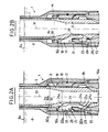
- FIGS. 2A and 2B are sectional views through an axial plane of symmetry and on a larger scale of the lower part of the lifting and handling grab.
- FIG. 2B shows the lower part of the lifting and handling device in the released position of the fuel assembly immersed in the liquid metal.
- the upper part of the lifting and handling grab is generally designated by the reference 1.
- the grapple 1 mainly comprises an external tubular body 2 and a slide 3 disposed inside the tubular body 2 and in its axial direction, with a certain radial clearance, the outside diameter of the slide 3 being substantially less than the inside diameter of the tubular body 2.
- the tubular body 2 is connected at its upper part to a housing 4 secured to the lower part of a lifting mast 5 of tubular shape which can be actuated to lift or lower the entire grapple vertically, by a device such as a winch not shown in FIG. 1 and connected to the upper part of the mast 5.
- the lifting mast 5 is associated with the fuel loading machine of the nuclear reactor in which the lifting grapple is used, the mast 5 passing through a rotating plug 6 rotatably mounted on the horizontal slab for closing the reactor vessel .
- the lifting device such as a winch connected to the upper part of the mast 5 and not shown in FIG. 1 is mounted, in this case, on the frame of the fuel loading machine. This device makes it possible to move the mast 5 and the entire lifting grab 1, in the vertical direction up or down (arrow 7).
- the reactor vessel contains liquid sodium 8 surmounted by a gaseous atmosphere 9 constituted by an inert gas such as argon.
- the housing 4 and the upper part of the tubular body 2 and of the slide 3 remain constantly immersed in the gaseous atmosphere 9.
- the lower part of the lifting grab 1 is introduced into the liquid sodium 8 in order to take up and handle the fuel assemblies in the reactor core submerged below the sodium level.
- the upper end part of the slide 3 disposed above the upper end of the tubular body 2 is engaged in the housing 4 and mounted sliding in the housing 4 by means of bearings 10.
- the upper part of the slide 3 is also connected in an articulated manner to two rods 11 pivotally mounted by means of an axis 12 on the casing 4.
- the end of the rods 11 opposite to the slide 3 is connected in an articulated manner to a rod actuator 13 arranged along the axis of the lifting mast 5. Any other mechanical system causing axial relative movement between the slide 3 and the tube 2 can be used.
- the upper end part of the actuating rod 13, not shown in FIG. 1, is accessible from the platform of the fuel loading machine to which the upper part of the mast 5 is connected, to allow the displacement of the rod 13 in the vertical direction up or down, so as to move the slider 3 in the vertical direction, as shown in the arrow 14.
- FIGS. 2A and 2B the lower part of the lifting and handling grab 1 is shown immersed in the liquid sodium 8 contained in the reactor vessel and in a position above the head 15 of a fuel assembly of the reactor core allowing this assembly to be taken up by the gripper gripping means.
- the lower part of the tubular body 2 of the grapple 1 diametrically widened constitutes a bell 16 open at its lower end 16a.
- three fingers 20 arranged at 120 ° from each other around the axis 19 of the tubular body 2 are mounted in the slots of the support 18 arranged at 120 ° from each other around the axis 19 of the tubular body 2 and bell 16.
- Each of the pivoting fingers 20 has a lower hooking portion 20a which is engaged, in the gripping position, as shown in FIG. 2A, in a groove 23 machined in the internal bore of the assembly head 15.
- the slide 3 is produced in tubular form and has in its lower part an area in which the wall of the tubular envelope of the slide is substantially greater than the thickness of the wall of the slide in its current part.
- cavities such as 24 are machined, at their upper part and at their lower part respectively, by ramps 24a and 24b inclined with respect to the axis 19, in one direction and in the other.
- Each of the fingers 20 comprises an upper actuating ramp 25a and a lower ramp 25b constituting the inner part of the attachment end 20a of the finger 20.
- the ramps 24b of the cavities 24 terminate towards the outside of the slide 3, by a support flange 24c substantially perpendicular to the axis 19 common to the tubular body 2 and to the slide 3.
- the downward movement of the slide 3 inside the tubular body 2 which can be controlled by the actuating rod 13 causes, when the fingers are in their gripping position as shown in FIG. 2A, bringing the ramps 24a and 25a into contact causing the tilting of the upper part of each of the fingers 20 towards the outside of the grapple, to reach the open position of the fingers, as shown in the figure 2B.
- the lower part 20a is then located in the cavity 24 outside the groove 23.
- the upward movement of the slide 3 stops when the support rim 24c of the slide comes to rest on the lower edge of the attachment portion 20a of the fingers 20.
- the grab 1 can then be lifted by means of the lifting mast 5 and of the housing 4 shown in FIG. 1.
- the attachment portion 20a of the fingers 20 comes to bear on the upper edge of the groove 23, so that during the lifting the weight of the assembly is supported by the slide 3 on which the assembly head 15 is supported by the hooking parts 20a of the fingers 20.
- the support of the assembly during lifting can also be provided, in a redundant manner, by the bell-shaped lower part 16 of the tubular body. 2, via the fingers 20 and their hinge pins 21.
- the devices according to the prior art do not allow the movement of an object such as a fuel assembly between a position immersed in a liquid metal and a position emerged in a gaseous atmosphere at a temperature below the temperature of solidification of the liquid metal, the pivoting fingers and their control mechanism being immersed in the liquid metal during the operation of taking the assembly.
- the pivoting fingers and the control mechanism are capable of retaining liquid metal, when the fuel assembly is raised above the level of the liquid metal, the fingers and the control mechanism then being in an atmosphere gas at a temperature below the solidification temperature of the liquid metal. The solidification of the liquid metal retained by the fingers and the control mechanism then risks preventing any possibility of opening the fingers.
- the lower part of the grapple is disposed inside the enlarged part 16 of the tubular casing 2 constituting a bell; the bell 16 is closed in leaktight manner at its upper part by an axially deformable element ensuring the junction between the slide and the internal surface of the bell 16.
- the deformable element 30 is constituted by a bellows comprising two coaxial envelopes 30a and 30b having successive waves in the axial direction.
- the corrugated walls of the bellows can be made, for example, of stainless steel.
- the bell 16 has, in its upper part, a part 16b projecting radially inwards relative to its internal surface, this projecting part 16b having the shape of a crown whose triangular section is visible in FIGS. 2A and 2B.
- the slider 3 comprises, on its external surface, a part 3b projecting radially outwards having the shape of a crown whose triangular section is visible in FIGS. 2A and 2B.
- the double-envelope bellows 30 is fixed by welding between the crowns 3b and 16b, the ends of the envelopes of the bellows 30 being tightly fixed by welding on the crowns 3b and 16b.
- the support 18 and the fingers 20 are fixed inside the bell 16, in the annular space 31, in an axial position intermediate between the bellows 30 and the lower open end 16a of the bell 16.
- the slide can be moved axially to actuate the fingers, as can be seen in FIGS. 2A and 2B.
- the bellows 30 is compressed as it can be seen in FIG. 2B.
- the bellows relaxes by elasticity, during the upward movement of the slide 3 realizing the closing of the fingers as shown in FIG. 2A.
- the slide 3 produced in tubular form can be used for blowing a cooling gas inside an assembly on which the grapple is engaged, during handling of the assembly above the level of the metal liquid.
- the grapple 1 is moved by means of the lifting mast 5 from a position situated above the level of the liquid metal to the position shown in FIG. 2B where the bell covers the head 15 of an assembly, the slide 3 being in its low position and the bellows 30 being compressed.
- the installation of the bell 16 on the assembly head 15 is facilitated by the fact that the bell 16 has a lower part with an enlarged diameter and that its lower opening 16a is chamfered inwards.
- inert gas such as argon fills the annular space 31 and the interior volume of the tubular slide 3.
- the gas contained in the internal volume of the slide 3 can escape inside the slide which is connected at its upper part to a device for blowing cooling gas.
- the gripping fingers 20 and their control means therefore remain constantly immersed in a gaseous atmosphere, during the positioning of the gripper on the assembly head 15 and during the operation of the fingers 20.
- the fingers 20 and their control mechanism are therefore not likely to come into contact with liquid metal which can freeze on the moving parts of the fingers.
- the assembly can therefore be moved thanks to the lifting grab 1, between its submerged position and a position emerged in the gaseous atmosphere located above the level of the liquid metal, without this operation being accompanied by a freezing of metal. liquid on the moving parts of the grapple.
- the assembly can therefore be moved and handled, from its submerged position, using only the lifting grab 1 which can operate successively in the liquid metal and in the gaseous atmosphere surmounting the liquid metal.
- the level of the liquid metal inside the slide remains identical to the upper level 8a of the liquid metal in the reactor vessel.
- the lifting grab according to the invention therefore makes it possible to carry out, in a simple and rapid manner, handling operations consisting in moving fuel assemblies from a position immersed in a liquid metal to an emerged position in which the fuel assembly is immersed in a gaseous atmosphere surmounting the liquid metal.
- the deformable elastic member can be constituted in a different form from a double-envelope bellows, as described above.
- the fingers of the grapple and their control means can be produced in a form different from that which has been described.
- the slide can be associated with an orientation lock variable, articulated on this slide and whose orientation is modified in the lower position of the slide by a fixed finger secured to the tubular body, the given orientation bringing the lock, according to its previous orientation, either to a relaxed position or to a locked position .
- the grapple lifting cable is connected to the slide on which the tubular body rests. When the tubular body comes to bear on the object which is being handled, the slide can move in the tubular body to its low position, by gravity. In this case, the entire grapple only has a lifting cable ensuring the operation of the slide and the transport of the tubular body and the load.
- the grapple according to the invention can be used to carry out any handling operation of any object such as a mechanical part to ensure its movement between a position immersed in a liquid metal or other hot liquid and an emerged position where the object is at least partially immersed in a gaseous atmosphere.
- the grapple according to the invention can be used, outside the field of nuclear reactors cooled by liquid metal and for example in applications using a bath of molten salts.
- lifting grab can be associated with handling means making it possible to move the object not only in the vertical direction but also in one or more horizontal directions.
Landscapes
- Physics & Mathematics (AREA)
- Engineering & Computer Science (AREA)
- Plasma & Fusion (AREA)
- General Engineering & Computer Science (AREA)
- High Energy & Nuclear Physics (AREA)
- Load-Engaging Elements For Cranes (AREA)
- Manipulator (AREA)
Abstract
Description
L'invention concerne un grappin de levage et de déplacement d'un assemblage combustible, entre une position immergée dans un metal liquide, tel que le sodium, et une position émergée dans un gaz froid, ou de tout autre objet entre une position immergée dans un métal liquide ou autre liquide chaud, tel qu'un bain de sels fondus, et une position émergée dans un gaz.The invention relates to a gripper for lifting and moving a fuel assembly, between a position immersed in a liquid metal, such as sodium, and a position emerged in a cold gas, or of any other object between a position immersed in a liquid metal or other hot liquid, such as a molten salt bath, and an emerged position in a gas.
Dans le cadre de l'exploitation des réacteurs nucléaires à neutrons rapides dont le liquide de refroidissement est généralement constitué par un métal liquide tel que le sodium, il est nécessaire d'assurer des opérations de manutention sur des assemblages combustibles ou des pièces mécaniques immergées dans le métal liquide de refroidissement du réacteur contenu dans la cuve du réacteur. Il peut être nécessaire également d'effectuer des opérations de manutention sur des assemblages combustibles ou des pièces mécaniques disposés dans des capacités remplies de sodium liquide et associées à la cuve du réacteur. Ces opérations de manutention peuvent être nécessaires en particulier pour assurer le stockage d'assemblages combustibles irradiés ou le remplacement d'assemblages dans le coeur du réacteur.In the context of the operation of fast neutron nuclear reactors, the coolant of which is generally constituted by a liquid metal such as sodium, it is necessary to provide handling operations on fuel assemblies or mechanical parts immersed in the reactor coolant metal contained in the reactor vessel. It may also be necessary to carry out handling operations on fuel assemblies or mechanical parts arranged in capacities filled with liquid sodium and associated with the reactor vessel. These handling operations may be necessary in particular to ensure the storage of irradiated fuel assemblies or the replacement of assemblies in the reactor core.
Dans un réacteur, le niveau supérieur du métal liquide est surmonté par une atmosphère gazeuse généralement constituée par un gaz inerte, les métaux liquides tels que le sodium étant extrêmement réactifs et susceptibles de s'enflammer spontanément au contact de l'oxygène.In a reactor, the upper level of the liquid metal is overcome by a gaseous atmosphere generally constituted by an inert gas, the liquid metals such as sodium being extremely reactive and liable to ignite spontaneously on contact with oxygen.
En dehors du domaine des réacteurs nucléaires utilisant un métal liquide pour leur refroidissement, il peut être nécessaire d'effectuer des manutentions alternatives entre une zone en gaz froid et une zone contenant un liquide chaud, ce qui risque de contrarier le fonctionnement du grappin.Outside the field of nuclear reactors using a liquid metal for their cooling, it may be necessary to carry out alternative handling between a zone in cold gas and a zone containing a hot liquid, which is likely to interfere with the operation of the grapple.
On connaît des grappins de type mécanique comportant des doigts de préhension qui peuvent être commandés à distance pour assurer la prise ou le relâchement d'un objet tel qu'un assemblage combustible.Grapples of the mechanical type are known comprising gripping fingers which can be controlled remotely to ensure the gripping or the relaxation of an object such as a fuel assembly.
De tels grappins peuvent être conçus pour fonctionner alors qu'ils sont immergés dans un métal liquide tel que le sodium.Such grapples can be designed to operate while immersed in a liquid metal such as sodium.
Une partie au moins des pièces constituant le grappin et en particulier les organes de préhension de ce grappin sont constamment immergés dans le sodium liquide et fonctionnent à une température supérieure à la température de solidification de ce métal liquide.At least part of the parts constituting the grab and in particular the gripping members of this grab are constantly immersed in liquid sodium and operate at a temperature higher than the solidification temperature of this liquid metal.
De tels grappins mécaniques peuvent bien sûr être également conçus pour être utilisés dans une atmosphère gazeuse. Ils ne sont jamais immergés.Such mechanical grippers can of course also be designed to be used in a gaseous atmosphere. They are never submerged.
Cependant, dans le cas d'opérations de manutention sur des objets tels que des assemblages combustibles immergés dans un métal liquide chaud, par exemple pour extraire ces objets du métal liquide et pour les évacuer dans une zone occupée par une atmosphère gazeuse à température inférieure à la température de solidification du métal liquide, il n'est pas possible d'utiliser ces grappins mécaniques, du métal liquide étant susceptible de se déposer et de se figer sur les organes mobiles du grappin, au moment où le grappin passe d'une position immergée dans le métal liquide à une position émergée dans laquelle le grappin se trouve plongé dans une atmosphère gazeuse dont la température est inférieure à la température de figeage du métal liquide. Le figeage du métal liquide sur les organes mobiles du grappin peut se traduire par un fonctionnement défectueux de ce grappin et en particulier par une impossibilité d'ouvrir les doigts du grappin et de libérer l'objet dont on assure la manutention.However, in the case of handling operations on objects such as fuel assemblies immersed in a hot liquid metal, for example to extract these objects from the liquid metal and to evacuate them in an area occupied by a gaseous atmosphere at a temperature below the solidification temperature of the liquid metal, it is not possible to use these mechanical grippers, liquid metal being capable of depositing and freezing on the movable members of the grab, when the grab passes from a position immersed in the liquid metal at an emerged position in which the grapple is immersed in a gaseous atmosphere whose temperature is lower than the freezing temperature of the liquid metal. The freezing of the liquid metal on the movable parts of the grab can result in a faulty operation of this grab and in particular by an impossibility of opening the fingers of the grab and of releasing the object which is being handled.
Pour effectuer des opérations de manutention d'objets tels que des assemblages combustibles immergés dans un métal liquide, on utilise généralement deux grappins différents, les opérations de manutention s'effectuant en deux temps.To carry out operations for handling objects such as fuel assemblies immersed in a liquid metal, two different grapples are generally used, the handling operations being carried out in two stages.
Un premier grappin fonctionnant uniquement à chaud, à une température supérieure à la température de figeage du métal liquide, permet d'assurer la prise de la tête de l'assemblage sous le niveau du métal liquide et le levage de la tête de l'assemblage de manière à la placer en position émergée au-dessus du niveau du métal liquide, et de lâcher la tête de l'assemblage dans une zone renfermant du gaz chaud.A first grapple operating only when hot, at a temperature higher than the freezing temperature of the liquid metal, makes it possible to take hold of the head of the assembly below the level of the liquid metal and lift the head of the assembly so as to place it in the emerged position above the level of the liquid metal, and to release the head of the assembly in an area containing hot gas.
On utilise alors un deuxième grappin fonctionnant uniquement sous atmosphère gazeuse chaude ou froide et donc non immergeable, pour effectuer une seconde opération de manutention qui consiste à reprendre la tête de l'assemblage qui a été précédemment sortie du métal liquide. Le second grappin effectue ensuite le levage et la manutention de l'assemblage combustible, sous atmosphère gazeuse.A second grapple is then used, operating only under a hot or cold gaseous atmosphere and therefore not immersible, to carry out a second handling operation which consists in taking up the head of the assembly which has previously been removed from the liquid metal. The second grapple then performs the lifting and handling of the fuel assembly, under a gaseous atmosphere.
Cette technique présente l'inconvénient de nécessiter l'utilisation de deux moyens de manutention différents au cours de deux phases successives de l'opération de manutention.This technique has the drawback of requiring the use of two different handling means during two successive phases of the handling operation.
On connaît des grappins mécaniques constitués par un corps tubulaire relié à l'une de ses extrémités à un moyen de levage et dans lequel sont montés des moyens de préhension tels que des griffes d'accrochage, mobiles dans la direction radiale du corps tubulaire entre une position de prise et une position de relâchement de l'objet dont on assure la manutention. Un coulisseau monté glissant dans la direction axiale du corps tubulaire et relié à des moyens de déplacement axial permet d'actionner à distance les moyens de préhension du grappin.There are known mechanical grippers constituted by a tubular body connected at one of its ends to a lifting means and in which are mounted gripping means such as hooking claws, movable in the radial direction of the tubular body between a grip position and a release position of the object which is being handled. A slide mounted sliding in the axial direction of the tubular body and connected to axial displacement means allows actuate the gripping means from a distance.
Un tel dispositif n'a cependant jamais été conçu de manière qu'il puisse être utilisé pour déplacer un objet entre une position immergée dans un métal liquide et une position émergée dans une atmosphère gazeuse chaude ou froide.However, such a device has never been designed so that it can be used to move an object between a position immersed in a liquid metal and a position emerged in a hot or cold gaseous atmosphere.
Le but de l'invention est donc de proposer un grappin de levage et de déplacement d'un objet entre une position immergée dans un liquide chaud tel qu'un métal fondu et une position émergée dans une atmosphère gazeuse, le grappin comportant un corps de forme tubulaire relié à un moyen de levage et un coulisseau monté glissant dans la direction axiale à l'intérieur du corps tubulaire ainsi que des moyens de préhension de l'objet montés à l'intérieur du corps tubulaire, mobiles radialement entre une position de prise et une position de relâchement de l'objet, le déplacement radial des moyens de préhension étant assuré par déplacement axial du coulisseau à l'intérieur du corps tubulaire ; ce grappin pouvant fonctionner de manière satisfaisante, au cours de phases successives dans le temps, à l'intérieur du liquide chaud et dans une atmosphère gazeuse.The object of the invention is therefore to provide a gripper for lifting and moving an object between a position immersed in a hot liquid such as a molten metal and a position emerged in a gaseous atmosphere, the gripper comprising a body of tubular form connected to a lifting means and a slider mounted sliding in the axial direction inside the tubular body as well as means for gripping the object mounted inside the tubular body, radially movable between a gripping position and a position for releasing the object, the radial movement of the gripping means being ensured by axial movement of the slide inside the tubular body; this grapple can operate satisfactorily, during successive phases over time, inside the hot liquid and in a gaseous atmosphere.
Dans ce but, le corps tubulaire du grappin selon l'invention comporte une partie d'extrémité ouverte en forme de cloche à l'intérieur de laquelle le coulisseau est relié à la surface interne du corps tubulaire, sur toute sa périphérie par un organe élastique déformable dans la direction axiale et étanche aux gaz, les moyens de préhension étant disposés à l'intérieur de la partie d'extrémité en forme de cloche de l'élément tubulaire, entre l'organe élastique assurant sa fermeture et son extrémité ouverte, de manière que, lors de l'introduction de la partie inférieure du corps tubulaire dans le liquide chaud pour assurer la prise et le déplacement de l'objet, du gaz soit emprisonné à l'intérieur de la cloche et constitue une réserve dans laquelle sont plongés les moyens de préhension pendant la prise et le déplacement de l'objet sous le niveau du liquide chaud.For this purpose, the tubular body of the grapple according to the invention comprises an open end portion in the shape of a bell inside which the slide is connected to the internal surface of the tubular body, over its entire periphery by an elastic member. deformable in the axial direction and gas tight, the gripping means being arranged inside the bell-shaped end portion of the tubular element, between the elastic member ensuring its closure and its open end, way that when introducing the lower body tubular in the hot liquid to ensure the grip and movement of the object, gas is trapped inside the bell and constitutes a reserve in which the gripping means are immersed during the grip and movement of the object below the level of the hot liquid.
Afin de bien faire comprendre l'invention, on va maintenant décrire, à titre d'exemple non limitatif, en se référant aux figures jointes en annexe, un mode de réalisation d'un grappin de levage et de manutention suivant l'invention et son utilisation pour effectuer des opérations de manutention d'assemblages combustibles dans la cuve d'un réacteur nucléaire à neutrons rapides.In order to clearly understand the invention, a description will now be given, by way of nonlimiting example, with reference to the attached figures, of an embodiment of a lifting and handling grab according to the invention and its use for carrying out operations for handling fuel assemblies in the tank of a fast neutron nuclear reactor.
La figure 1 est une vue en élévation et en coupe partielle de la partie supérieure du grappin de levage et de manutention.Figure 1 is an elevational view in partial section of the upper part of the lifting and handling grab.
Les figures 2A et 2B sont des vues en coupe par un plan axial de symétrie et à plus grande échelle de la partie inférieure du grappin de levage et de manutention.FIGS. 2A and 2B are sectional views through an axial plane of symmetry and on a larger scale of the lower part of the lifting and handling grab.
La figure 2A montre la partie inférieure du grappin en position de prise d'un assemblage combustible en position immergée dans un métal liquide.FIG. 2A shows the lower part of the grapple in the gripping position of a fuel assembly in the submerged position in a liquid metal.
La figure 2B montre la partie inférieure du dispositif de levage et de manutention en position de relâchement de l'assemblage combustible immergé dans le métal liquide.FIG. 2B shows the lower part of the lifting and handling device in the released position of the fuel assembly immersed in the liquid metal.
Sur la figure 1, on voit la partie supérieure du grappin de levage et de manutention désigné de manière généralement par le repère 1.In FIG. 1, the upper part of the lifting and handling grab is generally designated by the reference 1.
Le grappin 1 comporte principalement un corps tubulaire externe 2 et un coulisseau 3 disposé à l'intérieur du corps tubulaire 2 et suivant sa direction axiale, avec un certain jeu radial, le diamètre extérieur du coulisseau 3 étant sensiblement inférieur au diamètre intérieur du corps tubulaire 2.The grapple 1 mainly comprises an external
Le corps tubulaire 2 est relié à sa partie supérieure à un boîtier 4 solidaire de la partie inférieure d'un mât de levage 5 de forme tubulaire qui peut être actionné pour assurer le levage ou la descente à la verticale de l'ensemble du grappin, par un dispositif tel qu'un treuil non représenté sur la figure 1 et relié à la partie supérieure du mât 5.The
De préférence, le mât de levage 5 est associé à la machine de chargement du combustible du réacteur nucléaire dans lequel on utilise le grappin de levage, le mât 5 traversant un bouchon tournant 6 monté rotatif sur la dalle horizontale de fermeture de la cuve du réacteur.Preferably, the
Le dispositif de levage tel qu'un treuil relié à la partie supérieure du mât 5 et non représenté sur la figure 1 est monté, dans ce cas, sur le bâti de la machine de chargement du combustible. Ce dispositif permet de déplacer le mât 5 et l'ensemble du grappin de levage 1, dans la direction verticale vers le haut ou vers le bas (flèche 7).The lifting device such as a winch connected to the upper part of the
La cuve du réacteur renferme du sodium liquide 8 surmonté par une atmosphère gazeuse 9 constituée par un gaz inerte tel que l'argon.The reactor vessel contains
Le boîtier 4 ainsi que la partie supérieure du corps tubulaire 2 et du coulisseau 3 restent constamment plongés dans l'atmosphère gazeuse 9. La partie inférieure du grappin de levage 1 est introduite dans le sodium liquide 8 pour effectuer la prise et la manutention d'assemblages combustibles dans le coeur du réacteur immergés sous le niveau du sodium.The
La partie d'extrémité supérieure du coulisseau 3 disposée au-dessus de l'extrémité supérieure du corps tubulaire 2 est engagée dans le boîtier 4 et montée glissante dans le boîtier 4 par l'intermédiaire de paliers 10.The upper end part of the
La partie supérieure du coulisseau 3 est également reliée de manière articulée à deux biellettes 11 montées pivotantes par l'intermédiaire d'un axe 12 sur le carter 4. L'extrémité des biellettes 11 opposée au coulisseau 3 est reliée de manière articulée à une tige d'actionnement 13 disposée suivant l'axe du mât de levage 5. Tout autre système mécanique provoquant un mouvement relatif axial entre le coulisseau 3 et le tube 2 peut être utilisé.The upper part of the
La partie d'extrémité supérieure de la tige d'actionnement 13, non représentée sur la figure 1, est accessible depuis la plateforme de la machine de chargement du combustible à laquelle est reliée la partie supérieure du mât 5, pour permettre le déplacement de la tige 13 dans la direction verticale vers le haut ou vers le bas, de manière à déplacer le coulisseau 3 dans la direction verticale, comme schématisé par la flèche 14.The upper end part of the
Sur les figures 2A et 2B, on a représenté la partie inférieure du grappin de levage et de manutention 1 immergé dans le sodium liquide 8 contenu dans la cuve du réacteur et dans une position au-dessus de la tête 15 d'un assemblage combustible du coeur du réacteur permettant la prise de cet assemblage par les moyens de préhension du grappin.In FIGS. 2A and 2B, the lower part of the lifting and handling grab 1 is shown immersed in the
La partie inférieure du corps tubulaire 2 du grappin 1 élargie diamétralement constitue une cloche 16 ouverte à son extrémité inférieure 16a.The lower part of the
Une pièce annulaire de support 18 est fixée dans l'alésage intérieur de la cloche 16, par l'intermédiaire d'une clavette ou d'un jonc 17. La pièce annulaire de support 18 comporte des lumières longitudinales dans chacune desquelles est disposé un doigt d'accrochage tel que 20 monté pivotant sur un axe horizontal 21 monté transversalement dans la lumière du support 18.An
De manière préférentielle, trois doigts 20 disposés à 120° les uns des autres autour de l'axe 19 du corps tubulaire 2 sont montés dans des lumières du support 18 disposées à 120° les uns des autres autour de l'axe 19 du corps tubulaire 2 et de la cloche 16.Preferably, three
Chacun des doigts pivotants 20 comporte une partie inférieure d'accrochage 20a qui est engagée, dans la position de prise du grappin, comme représenté sur la figure 2A, dans une gorge 23 usinée dans l'alésage intérieur de la tête d'assemblage 15.Each of the pivoting
Le coulisseau 3 est réalisé sous forme tubulaire et présente dans sa partie inférieure une zone dans laquelle la paroi de l'enveloppe tubulaire du coulisseau est sensiblement supérieure à l'épaisseur de la paroi du coulisseau dans sa partie courante.The
Dans cette partie d'épaisseur accrue, sont usinées des cavités telles que 24 délimitées, à leur partie supérieure et à leur partie inférieure respectivement, par des rampes 24a et 24b inclinées par rapport à l'axe 19, dans un sens et dans l'autre.In this part of increased thickness, cavities such as 24 are machined, at their upper part and at their lower part respectively, by
Comme il est visible sur les figures 2A et 2B, lorsque le coulisseau 3 est engagé à l'intérieur du corps tubulaire 2, les cavités 24 viennent se placer au niveau des doigts 20 pour assurer leur manoeuvre.As can be seen in FIGS. 2A and 2B, when the
Chacun des doigts 20 comporte une rampe supérieure d'actionnement 25a et une rampe inférieure 25b constituant la partie intérieure de l'extrémité d'accrochage 20a du doigt 20.Each of the
En outre, les rampes 24b des cavités 24 se terminent vers l'extérieur du coulisseau 3, par un rebord d'appui 24c sensiblement perpendiculaire à l'axe 19 commun au corps tubulaire 2 et au coulisseau 3.In addition, the
Comme il est visible sur les figures 2A et 2B, le déplacement vers le bas du coulisseau 3 à l'intérieur du corps tubulaire 2, qui peut être commandé par la tige d'actionnement 13 provoque, lorsque les doigts sont dans leur position de prise comme représenté sur la figure 2A, une mise en contact des rampes 24a et 25a provoquant le basculement de la partie supérieure de chacun des doigts 20 vers l'extérieur du grappin, pour atteindre la position d'ouverture des doigts, comme représenté sur la figure 2B. La partie inférieure 20a se trouve alors dans la cavité 24 à l'extérieur de la gorge 23.As can be seen in FIGS. 2A and 2B, the downward movement of the
A l'inverse, le déplacement vers le haut du coulisseau 3 entraîne le déplacement vers l'intérieur de la partie supérieure des doigts 20, par interaction des rampes 24b et 25b. Les doigts 20 viennent s'engager par leur partie d'accrochage 20a à l'intérieur de la gorge 23 de la tête d'assemblage 15.Conversely, the upward movement of the
Le déplacement vers le haut du coulisseau 3 s'arrête lorsque le rebord d'appui 24c du coulisseau vient en appui sur le bord inférieur de la partie d'accrochage 20a des doigts 20. Le grappin 1 peut alors être soulevé par l'intermédiaire du mât de levage 5 et du boîtier 4 représentés sur la figure 1. La partie d'accrochage 20a des doigts 20 vient en appui sur le rebord supérieur de la gorge 23, si bien que pendant le levage le poids de l'assemblage est supporté par le coulisseau 3 sur lequel la tête d'assemblage 15 est en appui par l'intermédiaire des parties d'accrochage 20a des doigts 20.The upward movement of the
Suivant la conception de la commande du grappin, le support de l'assemblage pendant le levage peut également être assuré, de manière redondante, par la partie inférieure 16 en forme de cloche du corps tubulaire 2, par l'intermédiaire des doigts 20 et de leurs axes d'articulation 21.Depending on the design of the grapple control, the support of the assembly during lifting can also be provided, in a redundant manner, by the bell-shaped
La structure et les caractéristiques de fonctionnement du mécanisme de commande du grappin 1 tel que décrites ci-dessus, se traduisant par un déplacement radial des doigts par basculement sous l'effet du déplacement axial d'un coulisseau à l'intérieur de la structure porteuse des doigts, sont bien connues de l'art antérieur, ce type de grappin pouvant être utilisé soit pour effectuer des opérations de manutention sur des assemblages plongés dans le sodium liquide, soit pour effectuer des opérations de manutention sur des assemblages disposés dans une atmosphère gazeuse à une température sensiblement inférieure à la température de solidification du métal liquide.The structure and operating characteristics of the control mechanism of the grapple 1 as described above, resulting in a radial displacement of the fingers by tilting under the effect of the axial displacement of a slide inside the carrying structure fingers are well known in the prior art, this type of grapple can be used either to carry out handling operations on assemblies immersed in liquid sodium, or to carry out handling operations on assemblies arranged in a gaseous atmosphere at a temperature substantially lower than the solidification temperature of the liquid metal.
Cependant, les dispositifs suivant l'art antérieur ne permettent pas de réaliser le déplacement d'un objet tel qu'un assemblage combustible entre une position immergée dans un métal liquide et une position émergée dans une atmosphère gazeuse à une température inférieure à la température de solidification du métal liquide, les doigts pivotants et leur mécanisme de commande étant immergés dans le métal liquide pendant l'opération de prise de l'assemblage. Il en résulte que les doigts pivotants et le mécanisme de commande sont susceptibles de retenir du métal liquide, lors du soulèvement de l'assemblage combustible au-dessus du niveau du métal liquide, les doigts et le mécanisme de commande se trouvant alors dans une atmosphère gazeuse à une température inférieure à la température de solidification du métal liquide. La solidification du métal liquide retenu par les doigts et le mécanisme de commande risque alors d'interdire toute possibilité d'ouverture des doigts.However, the devices according to the prior art do not allow the movement of an object such as a fuel assembly between a position immersed in a liquid metal and a position emerged in a gaseous atmosphere at a temperature below the temperature of solidification of the liquid metal, the pivoting fingers and their control mechanism being immersed in the liquid metal during the operation of taking the assembly. As a result, the pivoting fingers and the control mechanism are capable of retaining liquid metal, when the fuel assembly is raised above the level of the liquid metal, the fingers and the control mechanism then being in an atmosphere gas at a temperature below the solidification temperature of the liquid metal. The solidification of the liquid metal retained by the fingers and the control mechanism then risks preventing any possibility of opening the fingers.
Selon l'invention, la partie inférieure du grappin est disposée à l'intérieur de la partie élargie 16 de l'enveloppe tubulaire 2 constituant une cloche ; la cloche 16 est fermée de manière étanche à sa partie supérieure par un élément déformable axialement assurant la jonction entre le coulisseau et la surface interne de la cloche 16.According to the invention, the lower part of the grapple is disposed inside the
L'élément déformable 30 est constitué par un soufflet comportant deux enveloppes coaxiales 30a et 30b présentant des ondes successives dans la direction axiale. Les parois ondulées du soufflet peuvent être constituées par exemple par un acier inoxydable.The
La cloche 16 comporte, dans sa partie supérieure, une partie 16b en saillie radiale vers l'intérieur par rapport à sa surface intérieure, cette partie en saillie 16b ayant la forme d'une couronne dont la section triangulaire est visible sur les figures 2A et 2B.The
Le coulisseau 3 comporte, sur sa surface externe, une partie 3b en saillie radiale vers l'extérieur ayant la forme d'une couronne dont la section triangulaire est visible sur les figures 2A et 2B. Le soufflet à double enveloppe 30 est fixé par soudage entre les couronnes 3b et 16b, les extrémités des enveloppes du soufflet 30 étant fixées de manière étanche par soudage sur les couronnes 3b et 16b.The
De cette manière, l'espace annulaire 31 compris entre la surface intérieure de la cloche 16 et la surface extérieure du coulisseau 3 est fermé de manière étanche à sa partie supérieure par le soufflet 30.In this way, the
Le support 18 et les doigts 20 sont fixés à l'intérieur de la cloche 16, dans l'espace annulaire 31, dans une position axiale intermédiaire entre le soufflet 30 et l'extrémité ouverte inférieure 16a de la cloche 16.The
Malgré la présence d'un élément de jonction étanche entre le coulisseau 3 et le corps tubulaire 2, le coulisseau peut être déplacé axialement pour réaliser l'actionnement des doigts, comme il est visible sur les figures 2A et 2B. Lors du déplacement vers le bas du coulisseau pour réaliser l'ouverture des doigts, le soufflet 30 est comprimé comme il est visible sur la figure 2B. Le soufflet se détend par élasticité, lors du déplacement vers le haut du coulisseau 3 réalisant la fermeture des doigts comme représenté sur la figure 2A.Despite the presence of a sealed junction element between the
Le coulisseau 3 réalisé sous forme tubulaire peut être utilisé pour effectuer le soufflage d'un gaz de refroidissement à l'intérieur d'un assemblage sur lequel le grappin est en prise, lors des manutentions de l'assemblage au-dessus du niveau du métal liquide.The
Pour effectuer la prise d'un assemblage sous le niveau du métal liquide, le grappin 1 est déplacé grâce au mât de levage 5 depuis une position située au-dessus du niveau du métal liquide jusqu'à la position représentée sur la figure 2B où la cloche vient coiffer la tête 15 d'un assemblage, le coulisseau 3 étant dans sa position basse et le soufflet 30 étant comprimé.To take an assembly under the level of the liquid metal, the grapple 1 is moved by means of the
La mise en place de la cloche 16 sur la tête d'assemblage 15 est facilitée par le fait que la cloche 16 comporte une partie inférieure à diamètre élargie et que son ouverture inférieure 16a est chanfreinée vers l'intérieur.The installation of the
Pendant la descente du grappin de levage dans l'atmosphère gazeuse surmontant le métal liquide, du gaz inerte tel que de l'argon remplit l'espace annulaire 31 et le volume intérieur du coulisseau tubulaire 3.During the descent of the lifting grab in the gaseous atmosphere surmounting the liquid metal, inert gas such as argon fills the
Lorsque les parties inférieures de la cloche 16 et du coulisseau 3 pénètrent sous le niveau 8a du métal liquide 8, le gaz contenu dans l'espace annulaire 31 se trouve emprisonné entre le niveau du métal liquide et le soufflet étanche 30, ce gaz ne pouvant s'échapper vers le haut.When the lower parts of the
En revanche, le gaz contenu dans le volume intérieur du coulisseau 3 peut s'échapper à l'intérieur du coulisseau qui est relié à sa partie supérieure à un dispositif d'insufflation de gaz de refroidissement.On the other hand, the gas contained in the internal volume of the
Pendant la descente du grappin 1 dans le métal liquide, le gaz contenu dans l'espace annulaire 31 se trouve comprimé, de manière que le niveau 8b du métal liquide dans l'espace annulaire 31 reste en-dessous de la partie inférieure 20a des doigts 20 et du rebord d'appui 24c du coulisseau 3.During the descent of the grapple 1 into the liquid metal, the gas contained in the
Les doigts de préhension 20 et leur moyen de commande restent donc constamment plongés dans une atmosphère gazeuse, pendant la mise en place du grappin sur la tête d'assemblage 15 et lors de la manoeuvre des doigts 20.The gripping
Les doigts 20 et leur mécanisme de commande ne sont donc pas susceptibles de venir en contact avec du métal liquide pouvant se figer sur les parties mobiles des doigts.The
Il est bien évident que, pendant le levage de l'assemblage dans le métal liquide, les doigts 20 restent sous atmosphère gazeuse, le gaz contenu dans l'espace annulaire 31 qui subit une certaine détente ne pouvant s'échapper par la partie inférieure de la cloche 16.It is obvious that, during the lifting of the assembly in the liquid metal, the
L'assemblage peut donc être déplacé grâce au grappin de levage 1, entre sa position immergée et une position émergée dans l'atmosphère gazeuse située au-dessus du niveau du métal liquide, sans que cette manoeuvre s'accompagne d'un figeage de métal liquide sur les parties mobiles du grappin.The assembly can therefore be moved thanks to the lifting grab 1, between its submerged position and a position emerged in the gaseous atmosphere located above the level of the liquid metal, without this operation being accompanied by a freezing of metal. liquid on the moving parts of the grapple.
L'assemblage peut donc être déplacé et manutentionné, depuis sa position immergée, en utilisant uniquement le grappin de levage 1 qui peut fonctionner successivement dans le métal liquide et dans l'atmosphère gazeuse surmontant le métal liquide.The assembly can therefore be moved and handled, from its submerged position, using only the lifting grab 1 which can operate successively in the liquid metal and in the gaseous atmosphere surmounting the liquid metal.
Lors de l'immersion du grappin 1 dans le métal liquide, le niveau du métal liquide à l'intérieur du coulisseau reste identique au niveau supérieur 8a du métal liquide dans la cuve du réacteur.When the grapple 1 is immersed in the liquid metal, the level of the liquid metal inside the slide remains identical to the
Le grappin de levage suivant l'invention permet donc de réaliser de manière simple et rapide des opérations de manutention consistant à déplacer des assemblages combustibles depuis une position immergée dans un métal liquide jusqu'à une position émergée dans laquelle l'assemblage combustible est plongé dans une atmosphère gazeuse surmontant le métal liquide.The lifting grab according to the invention therefore makes it possible to carry out, in a simple and rapid manner, handling operations consisting in moving fuel assemblies from a position immersed in a liquid metal to an emerged position in which the fuel assembly is immersed in a gaseous atmosphere surmounting the liquid metal.
L'invention ne se limite pas au mode de réalisation qui a été décrit.The invention is not limited to the embodiment which has been described.
C'est ainsi que l'organe élastique déformable peut être constitué sous une forme différente d'un soufflet à double enveloppe, comme décrit plus haut.Thus the deformable elastic member can be constituted in a different form from a double-envelope bellows, as described above.
Les doigts du grappin et leur moyen de commande peuvent être réalisés sous une forme différente de celle qui a été décrite.The fingers of the grapple and their control means can be produced in a form different from that which has been described.
Le coulisseau peut être réalisé sous une forme différente de la forme tubulaire décrite ci-dessus qui permet l'insufflation de gaz de refroidissement dans un assemblage. Le coulisseau peut être constitué par une simple pièce pleine à la périphérie de laquelle est fixée l'une des extrémités de l'organe élastique déformable fixé à son autre extrémité sur la surface intérieure de la cloche.The slider can be produced in a form different from the tubular form described above which allows the blowing of cooling gas into an assembly. The slide can be constituted by a simple solid piece at the periphery of which is fixed one of the ends of the deformable elastic member fixed at its other end on the internal surface of the bell.
Comme décrit dans le FR-A-2.431.907, le coulisseau peut être associé à un verrou à orientation variable, articulé sur ce coulisseau et dont l'orientation est modifiée en position basse du coulisseau par un doigt fixe solidaire du corps tubulaire, l'orientation donnée amenant le verrou, selon son orientation antérieure, soit à une position relâchée soit à une position verrouillée. Le câble de levage du grappin est relié au coulisseau sur lequel repose le corps tubulaire. Lorsque le corps tubulaire vient en appui sur l'objet dont on assure la manutention, le coulisseau peut se déplacer dans le corps tubulaire jusqu'à sa position basse, par gravité. Dans ce cas, l'ensemble du grappin ne comporte qu'un câble de levage assurant la manoeuvre du coulisseau et le transport du corps tubulaire et de la charge.As described in FR-A-2,431,907, the slide can be associated with an orientation lock variable, articulated on this slide and whose orientation is modified in the lower position of the slide by a fixed finger secured to the tubular body, the given orientation bringing the lock, according to its previous orientation, either to a relaxed position or to a locked position . The grapple lifting cable is connected to the slide on which the tubular body rests. When the tubular body comes to bear on the object which is being handled, the slide can move in the tubular body to its low position, by gravity. In this case, the entire grapple only has a lifting cable ensuring the operation of the slide and the transport of the tubular body and the load.
Le grappin suivant l'invention peut être utilisé pour effectuer toute opération de manutention d'un objet quelconque tel qu'une pièce mécanique pour assurer son déplacement entre une position immergée dans un métal liquide ou autre liquide chaud et une position émergée où l'objet est plongé au moins partiellement dans une atmosphère gazeuse.The grapple according to the invention can be used to carry out any handling operation of any object such as a mechanical part to ensure its movement between a position immersed in a liquid metal or other hot liquid and an emerged position where the object is at least partially immersed in a gaseous atmosphere.
Le grappin suivant l'invention peut être utilisé, en dehors du domaine des réacteurs nucléaires refroidis par métal liquide et par exemple dans des applications mettant en oeuvre un bain de sels fondus.The grapple according to the invention can be used, outside the field of nuclear reactors cooled by liquid metal and for example in applications using a bath of molten salts.
Il est bien évident que le grappin de levage peut être associé à des moyens de manutention permettant de déplacer l'objet non seulement dans la direction verticale mais également dans une ou plusieurs directions horizontales.It is obvious that the lifting grab can be associated with handling means making it possible to move the object not only in the vertical direction but also in one or more horizontal directions.
Claims (9)
Applications Claiming Priority (2)
| Application Number | Priority Date | Filing Date | Title |
|---|---|---|---|
| FR9002046A FR2658654B1 (en) | 1990-02-20 | 1990-02-20 | GRAPPLE FOR LIFTING AND MOVING AN OBJECT BETWEEN A POSITION IMMERSED IN A HOT LIQUID SUCH AS A METAL AND A POSITION EMERGED IN A GAS. |
| FR9002046 | 1990-02-20 |
Publications (1)
| Publication Number | Publication Date |
|---|---|
| EP0443904A1 true EP0443904A1 (en) | 1991-08-28 |
Family
ID=9393921
Family Applications (1)
| Application Number | Title | Priority Date | Filing Date |
|---|---|---|---|
| EP91400327A Withdrawn EP0443904A1 (en) | 1990-02-20 | 1991-02-11 | Lifting and handling gripper for an object between a position immersed in a hot liquid, such as a metal, and a position surfaced in a gas |
Country Status (5)
| Country | Link |
|---|---|
| US (1) | US5128095A (en) |
| EP (1) | EP0443904A1 (en) |
| JP (1) | JP2945767B2 (en) |
| FR (1) | FR2658654B1 (en) |
| RU (1) | RU1838837C (en) |
Families Citing this family (3)
| Publication number | Priority date | Publication date | Assignee | Title |
|---|---|---|---|---|
| US6327322B1 (en) * | 1999-07-27 | 2001-12-04 | Westinghouse Electric Company Llc | Interlock assembly for burnable poison rod transfer device |
| CN108818590B (en) * | 2018-07-23 | 2022-12-30 | 中国地质大学(武汉) | Dexterous hand of liquid metal robot |
| CN117620960A (en) * | 2023-12-22 | 2024-03-01 | 中乌先楚核能科技有限公司 | A disassembly and assembly tool for underwater irradiation monitoring equipment |
Citations (4)
| Publication number | Priority date | Publication date | Assignee | Title |
|---|---|---|---|---|
| FR1157964A (en) * | 1956-09-11 | 1958-06-05 | Commissariat Energie Atomique | New device for loading and unloading active bars of an atomic cell |
| GB1009333A (en) * | 1961-02-17 | 1965-11-10 | Atomic Energy Authority Uk | Improvements relating to handling equipment for radioactive charges |
| FR2410866A1 (en) * | 1977-11-30 | 1979-06-29 | Savin Nikolai | NUCLEAR REACTOR |
| FR2582438A1 (en) * | 1985-05-21 | 1986-11-28 | Commissariat Energie Atomique | Handling and transportation cask for nuclear fuel assemblies and installation comprising a cask of this type |
Family Cites Families (4)
| Publication number | Priority date | Publication date | Assignee | Title |
|---|---|---|---|---|
| US3883012A (en) * | 1971-10-21 | 1975-05-13 | Transfer Systems | Dry cask handling system for shipping nuclear fuel |
| US4259153A (en) * | 1977-05-25 | 1981-03-31 | Pryamilov Jury S | Device for removal of fuel assemblies and cans of control and safety system from core of nuclear reactor |
| FR2431907A1 (en) * | 1978-07-28 | 1980-02-22 | Novatome Ind | AUTOMATIC GRAPPLE |
| US4713210A (en) * | 1985-11-18 | 1987-12-15 | General Electric Company | Control rod driveline and grapple |
-
1990
- 1990-02-20 FR FR9002046A patent/FR2658654B1/en not_active Expired - Fee Related
-
1991
- 1991-02-11 EP EP91400327A patent/EP0443904A1/en not_active Withdrawn
- 1991-02-19 JP JP3024740A patent/JP2945767B2/en not_active Expired - Fee Related
- 1991-02-19 RU SU914894433A patent/RU1838837C/en active
- 1991-02-20 US US07/658,323 patent/US5128095A/en not_active Expired - Fee Related
Patent Citations (4)
| Publication number | Priority date | Publication date | Assignee | Title |
|---|---|---|---|---|
| FR1157964A (en) * | 1956-09-11 | 1958-06-05 | Commissariat Energie Atomique | New device for loading and unloading active bars of an atomic cell |
| GB1009333A (en) * | 1961-02-17 | 1965-11-10 | Atomic Energy Authority Uk | Improvements relating to handling equipment for radioactive charges |
| FR2410866A1 (en) * | 1977-11-30 | 1979-06-29 | Savin Nikolai | NUCLEAR REACTOR |
| FR2582438A1 (en) * | 1985-05-21 | 1986-11-28 | Commissariat Energie Atomique | Handling and transportation cask for nuclear fuel assemblies and installation comprising a cask of this type |
Also Published As
| Publication number | Publication date |
|---|---|
| JP2945767B2 (en) | 1999-09-06 |
| FR2658654B1 (en) | 1994-01-07 |
| JPH0527085A (en) | 1993-02-05 |
| FR2658654A1 (en) | 1991-08-23 |
| RU1838837C (en) | 1993-08-30 |
| US5128095A (en) | 1992-07-07 |
Similar Documents
| Publication | Publication Date | Title |
|---|---|---|
| EP2609029B1 (en) | Device for handling drums, equipment for transferring powder material, and transfer method | |
| EP2617040B1 (en) | Device for the dry handling of nuclear fuel assemblies | |
| EP2741298B1 (en) | System for gripping and for locking/unlocking | |
| WO2004066312A1 (en) | Method for making a closed container, said closed container and its components | |
| EP0443904A1 (en) | Lifting and handling gripper for an object between a position immersed in a hot liquid, such as a metal, and a position surfaced in a gas | |
| EP2092533B1 (en) | Nuclear fuel transport device and method of loading/unloading said device | |
| EP2656352B1 (en) | Sytem for long-term storage with a ventilated storage canister for enclosing a containment canister containing radioactive materials | |
| EP0238767B1 (en) | Assembly of a removable and lockable guide ring with a plate and its application to a guide tube of a nuclear reactor | |
| EP0348250A1 (en) | Filter opening and closing device in a nuclear installation and method for filter cartridge assembly replacement | |
| EP0402231A1 (en) | Remote-control self-clamping device for gripping cylindrical barrels | |
| EP2789550B1 (en) | Handling and containment hood, use for handling sample-holders of nuclear materials, such as nuclear fuels | |
| FR2582438A1 (en) | Handling and transportation cask for nuclear fuel assemblies and installation comprising a cask of this type | |
| FR2625023A2 (en) | Coupling device between a transport container and a horizontal wall of a discharge enclosure | |
| EP0051241B1 (en) | Process and apparatus for handling elongated large objects | |
| EP0562913B1 (en) | Vessel containing several separated beds of solid material dischargeable by gravity without mixing of material | |
| CH507570A (en) | Handling arm | |
| EP0011005B1 (en) | Sampling head for the coolant of a nuclear reactor | |
| EP0463921A1 (en) | Device for opening and tight closure of a transfer passage between the central duct of a transportable hollow body and a vertical shaft arranged in a fixed structure | |
| EP0218485B1 (en) | Handling device for inserting and withdrawing an apparatus through an orifice of a sealed container | |
| FR2486295A1 (en) | Core for nuclear reactor with vertical axis - where part of core is used only as temporary storage zone for nuclear fuel rods, which can be removed by rotary tongs | |
| FR2576291A1 (en) | Paper bin with automatic locking | |
| FR2676140A1 (en) | Device for inserting an irradiation capsule into a cage (basket) integral with the internals of nuclear reactors | |
| EP0363266A1 (en) | Nuclear-fuel assembly transfer beam, and nuclear reactor comprising such a beam | |
| EP3084772B1 (en) | Device for mating with an irradiated fuel container under a nuclear facility pit and containing irradiated fuel | |
| FR2584154A1 (en) | Automatic grasping and setting-down hook operating by gravity |
Legal Events
| Date | Code | Title | Description |
|---|---|---|---|
| PUAI | Public reference made under article 153(3) epc to a published international application that has entered the european phase |
Free format text: ORIGINAL CODE: 0009012 |
|
| AK | Designated contracting states |
Kind code of ref document: A1 Designated state(s): BE DE GB IT |
|
| 17P | Request for examination filed |
Effective date: 19910807 |
|
| 17Q | First examination report despatched |
Effective date: 19940414 |
|
| STAA | Information on the status of an ep patent application or granted ep patent |
Free format text: STATUS: THE APPLICATION HAS BEEN WITHDRAWN |
|
| 18W | Application withdrawn |
Withdrawal date: 19940824 |