EP0443927A1 - Vorrichtung zum Laden und LÀ¶schen von Gütern - Google Patents
Vorrichtung zum Laden und LÀ¶schen von Gütern Download PDFInfo
- Publication number
- EP0443927A1 EP0443927A1 EP91400416A EP91400416A EP0443927A1 EP 0443927 A1 EP0443927 A1 EP 0443927A1 EP 91400416 A EP91400416 A EP 91400416A EP 91400416 A EP91400416 A EP 91400416A EP 0443927 A1 EP0443927 A1 EP 0443927A1
- Authority
- EP
- European Patent Office
- Prior art keywords
- carriage
- gantry
- recited
- chain
- plane
- Prior art date
- Legal status (The legal status is an assumption and is not a legal conclusion. Google has not performed a legal analysis and makes no representation as to the accuracy of the status listed.)
- Granted
Links
Images


Classifications
-
- B—PERFORMING OPERATIONS; TRANSPORTING
- B66—HOISTING; LIFTING; HAULING
- B66F—HOISTING, LIFTING, HAULING OR PUSHING, NOT OTHERWISE PROVIDED FOR, e.g. DEVICES WHICH APPLY A LIFTING OR PUSHING FORCE DIRECTLY TO THE SURFACE OF A LOAD
- B66F9/00—Devices for lifting or lowering bulky or heavy goods for loading or unloading purposes
- B66F9/02—Stationary loaders or unloaders, e.g. for sacks
- B66F9/04—Stationary loaders or unloaders, e.g. for sacks hydraulically actuated or controlled
-
- B—PERFORMING OPERATIONS; TRANSPORTING
- B66—HOISTING; LIFTING; HAULING
- B66F—HOISTING, LIFTING, HAULING OR PUSHING, NOT OTHERWISE PROVIDED FOR, e.g. DEVICES WHICH APPLY A LIFTING OR PUSHING FORCE DIRECTLY TO THE SURFACE OF A LOAD
- B66F5/00—Mobile jacks of the garage type mounted on wheels or rollers
-
- B—PERFORMING OPERATIONS; TRANSPORTING
- B66—HOISTING; LIFTING; HAULING
- B66F—HOISTING, LIFTING, HAULING OR PUSHING, NOT OTHERWISE PROVIDED FOR, e.g. DEVICES WHICH APPLY A LIFTING OR PUSHING FORCE DIRECTLY TO THE SURFACE OF A LOAD
- B66F7/00—Lifting frames, e.g. for lifting vehicles; Platform lifts
- B66F7/02—Lifting frames, e.g. for lifting vehicles; Platform lifts with platforms suspended from ropes, cables, or chains or screws and movable along pillars
- B66F7/04—Lifting frames, e.g. for lifting vehicles; Platform lifts with platforms suspended from ropes, cables, or chains or screws and movable along pillars hydraulically or pneumatically operated
-
- Y—GENERAL TAGGING OF NEW TECHNOLOGICAL DEVELOPMENTS; GENERAL TAGGING OF CROSS-SECTIONAL TECHNOLOGIES SPANNING OVER SEVERAL SECTIONS OF THE IPC; TECHNICAL SUBJECTS COVERED BY FORMER USPC CROSS-REFERENCE ART COLLECTIONS [XRACs] AND DIGESTS
- Y10—TECHNICAL SUBJECTS COVERED BY FORMER USPC
- Y10T—TECHNICAL SUBJECTS COVERED BY FORMER US CLASSIFICATION
- Y10T74/00—Machine element or mechanism
- Y10T74/18—Mechanical movements
- Y10T74/18568—Reciprocating or oscillating to or from alternating rotary
- Y10T74/18832—Reciprocating or oscillating to or from alternating rotary including flexible drive connector [e.g., belt, chain, strand, etc.]
Definitions
- This invention relates to apparatus for loading and unloading objects such as palletized loads.
- it relates to such apparatus in which a plurality of carriages alternate between two positions, such as a loading/unloading station on an assembly line and a position having access to the lift of a truck.
- Palletized loads are often loaded and unloaded using a plurality of carriages that alternate between two positions on a continuous looped track, which may be either in a horizontal plane (like a racetrack) or in a vertical plane (like a ferris wheel). While both these lay outs are relatively simple mechanically, they consume a relatively large amount of floor space. Accordingly, a need has been apparent for apparatus for alternating a plurality of carriages between two positions that would consume less floor space, even at the cost of some increase in the complexity of the mechanisms involved.
- the apparatus for loading and unloading objects includes a first carriage; first means for moving the first carriage back and forth in a straight line in a first plane between a first position and a second position; a second carriage; and second means for moving the second carriage back and forth between the first position and the second position such that, when the first carriage is in the first position, the second carriage is in the second position and, as the first carriage moves to the second position, the second carriage moves out of the first plane, then back into the first plane and into the first position.
- Figure 1 is a schematic side view of the invention showing the first carriage in its first position and the second carriage in its first position.
- Figure 2 is a schematic side view of the invention showing the first carriage in its first position and the second carriage in its second position.
- Figure 3 is a schematic side view of the invention showing the first carriage in its second position and the second carriage in its third position.
- Figure 4 is a schematic side view of the invention showing the first carriage in its second position and the second carriage in its fourth position.
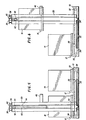
- Figure 5 is a side view of the invention showing the first carriage in its first position, the second carriage in its first position, the gantry in its first position, the apparatus for moving the first carriage back and forth between its first and second positions, the apparatus for moving the gantry back and forth between its first and second positions, and the apparatus for moving the second carriage up and down relative to the gantry.
- Figure 6 is a side view of the invention showing the first carriage in its second position, the second carriage in its third position, the gantry in its second position, the apparatus for moving the first carriage back and forth between its first and second positions, the apparatus for moving the gantry back and forth between its first and second positions, and the apparatus for moving the second carriage up and down relative to the gantry.
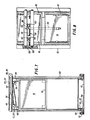
- Figure 7 is a partly cross sectional end view showing the second carriage in an upper position (i.e., either its second position or its third position), two of the wheels on which the gantry moves, and the apparatus for moving the second carriage up and down relative to the gantry.
- Figure 8 is a top view showing the apparatus for moving the second carriage up and down relative to the gantry, the apparatus for moving the first carriage back and forth between its first and second positions, and the apparatus for moving the gantry back and forth between its first and second positions.
- Figure 9 is a side view showing the first carriage in its first position, the second carriage in its first position, and the apparatus for moving the first carriage back and forth between its and first and second positions.
- Figure 10 is a partly cross sectional end view showing the second carriage in a lower position (i.e., either its first position or its fourth position), and the apparatus for moving the second carriage up and down relative to the gantry.
- Figures 1-4 illustrate the mode of operation of the invention in schematic form.
- the invention comprises a base 10 (which may be fabricated as a part of the assembly including the other components of the invention or which may be part of another facility on which the other components of the invention are mounted), a first carriage 12 (shown carrying a first palletized load 14), a second carriage 16 (shown carrying a second palletized load 18), and a gantry 20.
- the first carriage 12 is moved back and forth between a first position (shown in Figures 1 and 2) and a second position (shown in Figures 3 and 4); the second carriage 16 is moved from a first position (shown in Figure 1) which is identical to the second position of the first carriage 12 to a second position (shown in Figure 2), from the second position to a third position (shown in Figure 3), from the third position to a fourth position (shown in Figure 4) which is identical to the first position of the first carriage 12, and vice-versa; and the gantry 20 is moved back and forth between a first position (shown in Figures 1 and 2) and a second position (shown in Figures 3 and 4).
- a sequence of movements (which could be either a loading or an unloading sequence) will now be described.
- the first carriage 12 In the first stage of the sequence (shown in Figure 1), the first carriage 12 is on the right at ground level, and the second carriage 16 is on the left at ground level.
- the first carriage 12 In the second stage of the sequence (shown in Figure 2), the first carriage 12 remains on the right at ground level, and the second carriage 16 is moved vertically relative to the gantry 20 to an elevated position while remaining on the left.
- the first carriage 12 is moved from the right to the left while remaining at ground level, and the second carriage 16 is moved from the left to the right while remaining in an elevated position.
- the first carriage 12 remains on the left at ground level, and the second carriage 16 is moved vertically relative to the gantry 20 back to ground level while remaining on the right.
- the first carriage 12 and the second carriage 16 have exchanged positions.
- the sequence of motions is reversed. That is, the first carriage 12 remains at ground level and moves back to its first position, and the second carriage 16 is moved from its lower right position to its upper right position, from its upper right position to its upper left position, and from its upper left position to its lower left position.
- first and second carriages 12 and 16 are distinct and that each carriage follows a different path.
- the first carriage 12 does not move vertically, and the second carriage 16 does not move in a single linear path.
- the prime mover for the horizontal motion of both the first carriage 12 and the gantry 20 is a fluid cylinder 22 mounted on the base 10. While any convenient type of fluid cylinder (or, indeed, other types of prime movers) could be used, I prefer to use a cable cylinder incorporating a cable 24 (best seen in Figure 9). As will be explained subsequently with reference to Figure 9, the fluid cylinder 22 effects reciprocation of the first carriage 12. The first carriage 12 is in turn attached via a dog 26 on each transverse side to the top run of a cable 28.
- Each cable 28 is trained over a sheave 30 mounted at the left end of the base 10 (in Figures 5 and 6) and a sheave 32 mounted at the right end of the base 10.
- the gantry 20 is attached via a dog 34 on each transverse side to the bottom run of each cable 28.
- the prime mover for the vertical motion of the second carriage 16 is preferably a fluid cylinder 36 mounted on the gantry 20. (Of course, other types of prime movers could be substituted for the fluid cylinder 36.) Details of the fluid cylinder 36 are explained subsequently with reference to Figures 7 and 8. However, in Figures 5 and 6 it will be seen that two sheaves 38, 40 are preferably mounted on the fluid cylinder 36, that a cable 42 is trained over the sheave 38, that a cable 44 is trained over the sheave 40, and that one end of each of the cables 42, 44 is attached to the second carriage 16. Thus, when the fluid cylinder 36 is extended, the second carriage 16 is moved from its lower position to its upper position, and when the fluid cylinder 36 is retracted, the second carriage 16 is moved from its upper position to its lower position.
- a reinforcement bracket 46 is mounted on the gantry 20. It is preferably U shaped, and it receives the second carriage 16 when it is in its upper position. The purpose of the reinforcement bracket 46 is to reinforce the gantry 20.
- the cables 42, 44 are trained around the sheaves 38, 40 and sheaves 52, 54 mounted on the left side of the gantry 20 (in Figure 7).
- the active end of the cable 42 is attached to the second carriage 16 beneath the sheaves 52, 54.
- the active end of the cable 44 is trained around a sheave 56 and attached to the second carriage 16 beneath the sheave 56.
- the vertical motion of the second carriage 16 is approximately twice the horizontal motion of the piston rod 50.
- the gantry 20 is mounted on a plurality of wheels 58 that roll on a track 60 on each transverse side of the base 10.
- the first carriage 12 is mounted on a plurality of wheels 66 that roll on a track 68 on each transverse side of the base 10.
- Figure 10 is like Figure 7 except that it shows the second carriage 16 in its down position and that it shows the fluid cylinder 22.
Landscapes
- Engineering & Computer Science (AREA)
- Structural Engineering (AREA)
- Life Sciences & Earth Sciences (AREA)
- Geology (AREA)
- Mechanical Engineering (AREA)
- Civil Engineering (AREA)
- Transportation (AREA)
- Warehouses Or Storage Devices (AREA)
- Intermediate Stations On Conveyors (AREA)
- Forklifts And Lifting Vehicles (AREA)
- Reciprocating Conveyors (AREA)
- Specific Conveyance Elements (AREA)
Applications Claiming Priority (2)
| Application Number | Priority Date | Filing Date | Title |
|---|---|---|---|
| US481432 | 1990-02-20 | ||
| US07/481,432 US5020382A (en) | 1990-02-20 | 1990-02-20 | Apparatus for loading and unloading objects |
Publications (2)
| Publication Number | Publication Date |
|---|---|
| EP0443927A1 true EP0443927A1 (de) | 1991-08-28 |
| EP0443927B1 EP0443927B1 (de) | 1996-07-03 |
Family
ID=23911920
Family Applications (1)
| Application Number | Title | Priority Date | Filing Date |
|---|---|---|---|
| EP91400416A Expired - Lifetime EP0443927B1 (de) | 1990-02-20 | 1991-02-18 | Vorrichtung zum Laden und Löschen von Gütern |
Country Status (7)
| Country | Link |
|---|---|
| US (2) | US5020382A (de) |
| EP (1) | EP0443927B1 (de) |
| JP (1) | JPH06166402A (de) |
| KR (1) | KR910021337A (de) |
| AT (1) | ATE139980T1 (de) |
| CA (1) | CA2036702C (de) |
| DE (1) | DE69120553T2 (de) |
Cited By (2)
| Publication number | Priority date | Publication date | Assignee | Title |
|---|---|---|---|---|
| EP0872445A3 (de) * | 1997-04-14 | 2000-02-23 | INDUMAT GmbH & Co. KG Transport- und Lagersysteme | Transportsystem |
| EP2636618A1 (de) * | 2012-03-07 | 2013-09-11 | Krones Aktiengesellschaft | Fahrerloses Transportsystem einer Fertigungs- und/oder Verpackungsanlage und Verfahren zu deren Steuerung |
Families Citing this family (8)
| Publication number | Priority date | Publication date | Assignee | Title |
|---|---|---|---|---|
| US5160237A (en) * | 1991-03-11 | 1992-11-03 | Lutz David W | Apparatus for loading and unloading objects |
| US5310305A (en) * | 1991-09-11 | 1994-05-10 | Master Manufacturers, Inc. | Apparatus for loading and unloading objects |
| US5782317A (en) * | 1996-04-16 | 1998-07-21 | Master Manufacturers, Inc. | Transport apparatus for vertically moving objects and method |
| DE102009047408A1 (de) * | 2009-12-02 | 2011-06-09 | Hauni Maschinenbau Ag | Verfahren und Vorrichtung zum Wechseln von Towballen |
| DE202019102585U1 (de) | 2019-05-08 | 2020-08-11 | Klaus Multiparking Gmbh | Vorrichtung zum Abstellen von Gegenständen mit horizontal orientiertem Antrieb |
| US12077380B2 (en) * | 2020-04-06 | 2024-09-03 | Sailrail Automated Systems, Inc. | Cart loader/unloader and a switcher system and improvements therein |
| US11655100B2 (en) * | 2020-04-06 | 2023-05-23 | Sailrail Automated Systems, Inc. | Cart loader/unloader and a switcher system |
| DE102022134614A1 (de) * | 2022-12-22 | 2024-06-27 | Fft Produktionssysteme Gmbh & Co. Kg | Vorrichtung zum Bereitstellen von Ladungsträgern, Fertigungssystem sowie Verfahren zum Bereitstellen von Ladungsträgern für einen Fertigungsprozess |
Citations (3)
| Publication number | Priority date | Publication date | Assignee | Title |
|---|---|---|---|---|
| US4143780A (en) * | 1977-03-11 | 1979-03-13 | Karl Schnell | Lifting device for feeding a processing machine |
| FR2478597A1 (fr) * | 1980-03-20 | 1981-09-25 | Blanc Philippe | Dispositif pour la manipulation de palettes |
| DE3027993A1 (de) * | 1980-07-24 | 1982-02-25 | Holstein Und Kappert Gmbh, 4600 Dortmund | Vorrichtung zum baladen von paletten |
Family Cites Families (7)
| Publication number | Priority date | Publication date | Assignee | Title |
|---|---|---|---|---|
| US3047095A (en) * | 1960-05-06 | 1962-07-31 | American Can Co | Pallet elevator |
| US3074563A (en) * | 1961-12-13 | 1963-01-22 | Pacific Coast Eng Co | Fold-in boom |
| US3447697A (en) * | 1966-04-04 | 1969-06-03 | Whiting Corp | Article handling apparatus |
| DE7718050U1 (de) * | 1977-06-08 | 1979-01-04 | Theobald, Adolf, 5758 Froendenberg | Vorrichtung zur speicherung von fuer die vorratshaltung dienenden paletten |
| US4450400A (en) * | 1981-12-04 | 1984-05-22 | Gwyn Marion V | Battery replacement system for electric vehicles |
| US4568233A (en) * | 1984-08-06 | 1986-02-04 | Harnischfeger Corporation | Storage and retrieval apparatus |
| IT1187347B (it) * | 1985-03-29 | 1987-12-23 | Decco Roda Spa | Macchina automatica per il prelievo da almeno una stazione di carico e l'accatastamento e/o il deposito su almeno una stazione di scarico di cassoni particolarmente di prodotti ortofrutticoli selezionati |
-
1990
- 1990-02-20 US US07/481,432 patent/US5020382A/en not_active Ceased
-
1991
- 1991-02-18 DE DE69120553T patent/DE69120553T2/de not_active Expired - Fee Related
- 1991-02-18 AT AT91400416T patent/ATE139980T1/de not_active IP Right Cessation
- 1991-02-18 EP EP91400416A patent/EP0443927B1/de not_active Expired - Lifetime
- 1991-02-19 KR KR1019910002649A patent/KR910021337A/ko not_active Ceased
- 1991-02-19 JP JP3045407A patent/JPH06166402A/ja active Pending
- 1991-02-20 CA CA002036702A patent/CA2036702C/en not_active Expired - Fee Related
- 1991-07-23 US US07/734,488 patent/USRE34493E/en not_active Expired - Lifetime
Patent Citations (3)
| Publication number | Priority date | Publication date | Assignee | Title |
|---|---|---|---|---|
| US4143780A (en) * | 1977-03-11 | 1979-03-13 | Karl Schnell | Lifting device for feeding a processing machine |
| FR2478597A1 (fr) * | 1980-03-20 | 1981-09-25 | Blanc Philippe | Dispositif pour la manipulation de palettes |
| DE3027993A1 (de) * | 1980-07-24 | 1982-02-25 | Holstein Und Kappert Gmbh, 4600 Dortmund | Vorrichtung zum baladen von paletten |
Cited By (6)
| Publication number | Priority date | Publication date | Assignee | Title |
|---|---|---|---|---|
| EP0872445A3 (de) * | 1997-04-14 | 2000-02-23 | INDUMAT GmbH & Co. KG Transport- und Lagersysteme | Transportsystem |
| EP2636618A1 (de) * | 2012-03-07 | 2013-09-11 | Krones Aktiengesellschaft | Fahrerloses Transportsystem einer Fertigungs- und/oder Verpackungsanlage und Verfahren zu deren Steuerung |
| DE102012203575A1 (de) * | 2012-03-07 | 2013-09-12 | Krones Ag | Fahrerloses Transportsystem einer Fertigungs- und/oder Verpackungsanlage und Verfahren zu deren Steuerung |
| CN103303642A (zh) * | 2012-03-07 | 2013-09-18 | 克罗内斯股份公司 | 制造和/或包装设备的无人驾驶式运输系统和其控制方法 |
| CN103303642B (zh) * | 2012-03-07 | 2016-05-11 | 克罗内斯股份公司 | 制造和/或包装设备的无人驾驶式运输系统和其控制方法 |
| EP2636618B1 (de) * | 2012-03-07 | 2017-06-07 | Krones Aktiengesellschaft | Fahrerloses Transportsystem einer Fertigungs- und/oder Verpackungsanlage und Verfahren zu deren Steuerung |
Also Published As
| Publication number | Publication date |
|---|---|
| DE69120553D1 (de) | 1996-08-08 |
| JPH06166402A (ja) | 1994-06-14 |
| EP0443927B1 (de) | 1996-07-03 |
| CA2036702A1 (en) | 1991-08-21 |
| ATE139980T1 (de) | 1996-07-15 |
| US5020382A (en) | 1991-06-04 |
| CA2036702C (en) | 1994-03-08 |
| USRE34493E (en) | 1994-01-04 |
| DE69120553T2 (de) | 1997-02-20 |
| KR910021337A (ko) | 1991-12-20 |
Similar Documents
| Publication | Publication Date | Title |
|---|---|---|
| US4747745A (en) | Selective beam gantry crane | |
| US5062760A (en) | Material handling system | |
| US4690609A (en) | Truck loading apparatus | |
| CN110422527B (zh) | 一种自动化立体仓库 | |
| US5020382A (en) | Apparatus for loading and unloading objects | |
| US4024968A (en) | Heavy lift side loader truck | |
| KR900001753B1 (ko) | 선박과 도크 사이에서의 화물 이동을 위한 안벽크레인 및 그 화물 이동방법 | |
| EP0133472A2 (de) | Vorrichtung zum senkrechten Stapeln von Behältern | |
| CA1274808A (en) | Transport for heavy loads | |
| US4523887A (en) | Stacker crane for narrow aisles | |
| US5515982A (en) | Telescoping shuttle for a cargo container handling crane | |
| CN108033183A (zh) | 一种货架穿梭车用换层机 | |
| US3176853A (en) | Mobile lift apparatus | |
| US3825128A (en) | Sway-arrest system | |
| US3313429A (en) | Vehicle loading and unloading apparatus | |
| CN114835026A (zh) | 一种小车可升降的双层集装箱岸桥 | |
| US5765981A (en) | Wire rope tensioning and reeving system for cargo container handling cranes | |
| US3805973A (en) | Storage and retrieval arrangement | |
| US5160237A (en) | Apparatus for loading and unloading objects | |
| CN216334440U (zh) | 一种多层物流仓库快速存取件装置 | |
| US5310305A (en) | Apparatus for loading and unloading objects | |
| JPS6349561A (ja) | 重荷重物の持上及び搬送用の搬送装置 | |
| CN209306290U (zh) | 一种板式家具柔性生产线用的有轨式巷道堆垛机 | |
| US3286853A (en) | Stacker crane power lift mechanism | |
| KR960000252B1 (ko) | 중량물(重量物)의 저장, 반송장치 |
Legal Events
| Date | Code | Title | Description |
|---|---|---|---|
| PUAI | Public reference made under article 153(3) epc to a published international application that has entered the european phase |
Free format text: ORIGINAL CODE: 0009012 |
|
| AK | Designated contracting states |
Kind code of ref document: A1 Designated state(s): AT BE CH DE DK ES FR GB GR IT LI LU NL SE |
|
| 17P | Request for examination filed |
Effective date: 19920222 |
|
| 17Q | First examination report despatched |
Effective date: 19940218 |
|
| GRAH | Despatch of communication of intention to grant a patent |
Free format text: ORIGINAL CODE: EPIDOS IGRA |
|
| GRAH | Despatch of communication of intention to grant a patent |
Free format text: ORIGINAL CODE: EPIDOS IGRA |
|
| GRAA | (expected) grant |
Free format text: ORIGINAL CODE: 0009210 |
|
| AK | Designated contracting states |
Kind code of ref document: B1 Designated state(s): AT BE CH DE DK ES FR GB GR IT LI LU NL SE |
|
| PG25 | Lapsed in a contracting state [announced via postgrant information from national office to epo] |
Ref country code: FR Free format text: THE PATENT HAS BEEN ANNULLED BY A DECISION OF A NATIONAL AUTHORITY Effective date: 19960703 Ref country code: DK Effective date: 19960703 Ref country code: AT Effective date: 19960703 Ref country code: LI Effective date: 19960703 Ref country code: GR Free format text: LAPSE BECAUSE OF FAILURE TO SUBMIT A TRANSLATION OF THE DESCRIPTION OR TO PAY THE FEE WITHIN THE PRESCRIBED TIME-LIMIT Effective date: 19960703 Ref country code: NL Free format text: LAPSE BECAUSE OF FAILURE TO SUBMIT A TRANSLATION OF THE DESCRIPTION OR TO PAY THE FEE WITHIN THE PRESCRIBED TIME-LIMIT Effective date: 19960703 Ref country code: ES Free format text: THE PATENT HAS BEEN ANNULLED BY A DECISION OF A NATIONAL AUTHORITY Effective date: 19960703 Ref country code: CH Effective date: 19960703 |
|
| REF | Corresponds to: |
Ref document number: 139980 Country of ref document: AT Date of ref document: 19960715 Kind code of ref document: T |
|
| REF | Corresponds to: |
Ref document number: 69120553 Country of ref document: DE Date of ref document: 19960808 |
|
| ITF | It: translation for a ep patent filed | ||
| PG25 | Lapsed in a contracting state [announced via postgrant information from national office to epo] |
Ref country code: SE Effective date: 19961003 |
|
| NLV1 | Nl: lapsed or annulled due to failure to fulfill the requirements of art. 29p and 29m of the patents act | ||
| EN | Fr: translation not filed | ||
| REG | Reference to a national code |
Ref country code: CH Ref legal event code: PL |
|
| PG25 | Lapsed in a contracting state [announced via postgrant information from national office to epo] |
Ref country code: LU Free format text: LAPSE BECAUSE OF NON-PAYMENT OF DUE FEES Effective date: 19970228 |
|
| PLBE | No opposition filed within time limit |
Free format text: ORIGINAL CODE: 0009261 |
|
| STAA | Information on the status of an ep patent application or granted ep patent |
Free format text: STATUS: NO OPPOSITION FILED WITHIN TIME LIMIT |
|
| 26N | No opposition filed | ||
| PGFP | Annual fee paid to national office [announced via postgrant information from national office to epo] |
Ref country code: GB Payment date: 19980216 Year of fee payment: 8 |
|
| PGFP | Annual fee paid to national office [announced via postgrant information from national office to epo] |
Ref country code: BE Payment date: 19980219 Year of fee payment: 8 |
|
| PGFP | Annual fee paid to national office [announced via postgrant information from national office to epo] |
Ref country code: DE Payment date: 19980316 Year of fee payment: 8 |
|
| PG25 | Lapsed in a contracting state [announced via postgrant information from national office to epo] |
Ref country code: GB Free format text: LAPSE BECAUSE OF NON-PAYMENT OF DUE FEES Effective date: 19990218 |
|
| PG25 | Lapsed in a contracting state [announced via postgrant information from national office to epo] |
Ref country code: BE Free format text: LAPSE BECAUSE OF NON-PAYMENT OF DUE FEES Effective date: 19990228 |
|
| BERE | Be: lapsed |
Owner name: LUTZ DAVID W. Effective date: 19990228 |
|
| GBPC | Gb: european patent ceased through non-payment of renewal fee |
Effective date: 19990218 |
|
| PG25 | Lapsed in a contracting state [announced via postgrant information from national office to epo] |
Ref country code: DE Free format text: LAPSE BECAUSE OF NON-PAYMENT OF DUE FEES Effective date: 19991201 |
|
| PG25 | Lapsed in a contracting state [announced via postgrant information from national office to epo] |
Ref country code: IT Free format text: LAPSE BECAUSE OF NON-PAYMENT OF DUE FEES Effective date: 20050218 |
|
| REG | Reference to a national code |
Ref country code: FR Ref legal event code: ST Effective date: 20120309 |
|
| PG25 | Lapsed in a contracting state [announced via postgrant information from national office to epo] |
Ref country code: FR Free format text: THE PATENT HAS BEEN ANNULLED BY A DECISION OF A NATIONAL AUTHORITY Effective date: 19970228 |