EP0443993A1 - A suture ring for heart valve prostheses - Google Patents
A suture ring for heart valve prostheses Download PDFInfo
- Publication number
- EP0443993A1 EP0443993A1 EP91830057A EP91830057A EP0443993A1 EP 0443993 A1 EP0443993 A1 EP 0443993A1 EP 91830057 A EP91830057 A EP 91830057A EP 91830057 A EP91830057 A EP 91830057A EP 0443993 A1 EP0443993 A1 EP 0443993A1
- Authority
- EP
- European Patent Office
- Prior art keywords
- suture ring
- ring according
- suture
- materials
- intended
- Prior art date
- Legal status (The legal status is an assumption and is not a legal conclusion. Google has not performed a legal analysis and makes no representation as to the accuracy of the status listed.)
- Granted
Links
- 210000003709 heart valve Anatomy 0.000 title claims description 5
- 239000000463 material Substances 0.000 claims abstract description 43
- 239000008280 blood Substances 0.000 claims abstract description 10
- 210000004369 blood Anatomy 0.000 claims abstract description 10
- 230000017531 blood circulation Effects 0.000 claims abstract description 5
- 230000002949 hemolytic effect Effects 0.000 claims abstract description 5
- 239000011148 porous material Substances 0.000 claims abstract description 5
- 239000005020 polyethylene terephthalate Substances 0.000 claims description 9
- -1 polyethylene terephthalate Polymers 0.000 claims description 8
- 229920000139 polyethylene terephthalate Polymers 0.000 claims description 5
- 229920004934 Dacron® Polymers 0.000 claims description 4
- 229920001343 polytetrafluoroethylene Polymers 0.000 claims description 4
- 210000004115 mitral valve Anatomy 0.000 claims description 3
- 239000003575 carbonaceous material Substances 0.000 claims description 2
- 239000011248 coating agent Substances 0.000 claims description 2
- 238000000576 coating method Methods 0.000 claims description 2
- 239000000470 constituent Substances 0.000 claims description 2
- 230000002885 thrombogenetic effect Effects 0.000 claims description 2
- 239000005871 repellent Substances 0.000 abstract description 5
- 239000004744 fabric Substances 0.000 description 6
- 239000007943 implant Substances 0.000 description 4
- 239000004809 Teflon Substances 0.000 description 2
- 229920006362 Teflon® Polymers 0.000 description 2
- 210000001765 aortic valve Anatomy 0.000 description 2
- 239000004810 polytetrafluoroethylene Substances 0.000 description 2
- 229920002994 synthetic fiber Polymers 0.000 description 2
- OKTJSMMVPCPJKN-UHFFFAOYSA-N Carbon Chemical compound [C] OKTJSMMVPCPJKN-UHFFFAOYSA-N 0.000 description 1
- 229920004943 Delrin® Polymers 0.000 description 1
- 229930040373 Paraformaldehyde Natural products 0.000 description 1
- 230000009286 beneficial effect Effects 0.000 description 1
- 239000000560 biocompatible material Substances 0.000 description 1
- 230000015572 biosynthetic process Effects 0.000 description 1
- 229910052799 carbon Inorganic materials 0.000 description 1
- 238000010276 construction Methods 0.000 description 1
- 238000002513 implantation Methods 0.000 description 1
- 230000014759 maintenance of location Effects 0.000 description 1
- 229920002866 paraformaldehyde Polymers 0.000 description 1
- 229920000642 polymer Polymers 0.000 description 1
- 239000000126 substance Substances 0.000 description 1
- 230000009424 thromboembolic effect Effects 0.000 description 1
- 238000011144 upstream manufacturing Methods 0.000 description 1
Images
Classifications
-
- A—HUMAN NECESSITIES
- A61—MEDICAL OR VETERINARY SCIENCE; HYGIENE
- A61F—FILTERS IMPLANTABLE INTO BLOOD VESSELS; PROSTHESES; DEVICES PROVIDING PATENCY TO, OR PREVENTING COLLAPSING OF, TUBULAR STRUCTURES OF THE BODY, e.g. STENTS; ORTHOPAEDIC, NURSING OR CONTRACEPTIVE DEVICES; FOMENTATION; TREATMENT OR PROTECTION OF EYES OR EARS; BANDAGES, DRESSINGS OR ABSORBENT PADS; FIRST-AID KITS
- A61F2/00—Filters implantable into blood vessels; Prostheses, i.e. artificial substitutes or replacements for parts of the body; Appliances for connecting them with the body; Devices providing patency to, or preventing collapsing of, tubular structures of the body, e.g. stents
- A61F2/02—Prostheses implantable into the body
- A61F2/24—Heart valves ; Vascular valves, e.g. venous valves; Heart implants, e.g. passive devices for improving the function of the native valve or the heart muscle; Transmyocardial revascularisation [TMR] devices; Valves implantable in the body
- A61F2/2409—Support rings therefor, e.g. for connecting valves to tissue
-
- Y—GENERAL TAGGING OF NEW TECHNOLOGICAL DEVELOPMENTS; GENERAL TAGGING OF CROSS-SECTIONAL TECHNOLOGIES SPANNING OVER SEVERAL SECTIONS OF THE IPC; TECHNICAL SUBJECTS COVERED BY FORMER USPC CROSS-REFERENCE ART COLLECTIONS [XRACs] AND DIGESTS
- Y10—TECHNICAL SUBJECTS COVERED BY FORMER USPC
- Y10S—TECHNICAL SUBJECTS COVERED BY FORMER USPC CROSS-REFERENCE ART COLLECTIONS [XRACs] AND DIGESTS
- Y10S623/00—Prosthesis, i.e. artificial body members, parts thereof, or aids and accessories therefor
- Y10S623/90—Stent for heart valve
Definitions
- the present invention relates to suture rings for heart valve prostheses and particularly concerns suture rings with internal surfaces which are intended to be exposed to the blood flow and external surfaces which are intended to be exposed to the tissue to which the prosthesis is sutured.
- suture rings are usually covered (and, in some cases, constituted entirely) by fabrics made of biocompatible synthetic materials which are intended to form a woven structure through which surgical stitches can be inserted to suture the prosthesis in its implant position after the removal of the natural valve flaps.
- the suture ring it is desirable for the suture ring not to absorb blood or cause any appreciable resistance to the blood flow which might have a haemolytic or thrombogenic effect.
- substantially water-repellent materials such as polytetrafluoroethylene (also known by the trade name of Teflon).
- substantially hydrophilic, porous materials such as, for example, polyethylene terephthalate (also known by the trade name of Dacron). These materials in turn are somewhat prone to absorbing blood and may also have a considerable haemolytic effect on the mass of blood to which the suture ring is exposed in use.
- the object of the present invention is to provide a suture ring for heart valve prostheses in which the aforesaid requirements can be satisfied simultaneously without giving rise to the problems described.
- a suture ring for heart valve prostheses is generally indicated 1.
- the ring in question is constituted substantially by a more or less flexible and resilient annular body which is intended to be fitted around the stent or housing of the valve prosthesis, not shown in the drawings, which supports the obturator means of the valve (pivoting obturators, etc.).
- the function of the suture ring is essentially to provide for and to stimulate the firm anchorage of the prosthesis in its implant position.
- the prosthesis in question may either be of the mechanical type with pivoting obturators or of the type with natural valve flaps.
- the suture ring 1 can be seen to include:
- an external loop is formed in the covering layer 3, 4 at one axial end of the core 2 and contains an annular mass of generally soft padding formed by several, for example, three, superposed layers 5a, 5b and 5c whose characteristics will be described further below.
- a loop is formed in the covering layer 3, 4 approximately in the middle of the external surface of the core 2; this loop also contains a mass of soft padding having a structure with several, for example, three, layers 6a, 6b and 6c.
- surgical stitches are intended to extend through the external loops of the suture rings and their padding to keep the suture ring (and hence the prosthesis) securely in its desired implant position.
- the main characteristic of the suture ring according to the invention is the selection of different materials for covering the surface 7 over which the blood passing through the axial orifice in the prosthesis is intended to flow when the prosthesis is in use, and for covering the surface 8 which is intended to be exposed to the tissue to which the prosthesis is sutured.
- the surface 7 is covered by a material 3 which is preferably constituted by a fabric of a substantially water-repellent synthetic material so that it absorbs substantially no blood and has little haemolytic effect.
- the material 3 is constituted by a polytetrafluoroethylene (Teflon) fabric, preferably of the type currently known in the art as "light Teflon”.
- Teflon polytetrafluoroethylene
- the water-repellent material 3 extends mainly along the edge of the core 2 of the ring and along the side of the suture loop at the end of the ring which is intended to be oriented upstream with respect to the blood flow through the prosthesis (the so-called "inflow" end); in other words, this is the end of the prosthesis over which the blood is intended to flow in use.
- the second covering layer 4 of hydrophilic, porous material extends from the opposite side of the suture loop over the entire outer surface of the core 2 and forms a turned-back portion 3′ facing the internal surface of the core 2 of the suture ring.
- the covering layer 4 is preferably made of polyethylene terephthalate (Dacron) with a velvety structure of the type currently known in the art as "double velour”.
- both the covering layer 3 and the turned-back portion 3′ are coated with a biocompatible carbon material preferably produced according to the criteria described in European patent applications Nos. 0 102 328 and 0 224 080, both in the name of the present Applicant.
- This coating improves the biocompatibility of the material to which it is applied and also modifies its behaviour to a certain extent as regards its haemocompatibility characteristics.
- the Applicant has found that the use of a material substantially similar to that used for the outer covering layer 4 (that is, polyethylene terephthalate) is particularly advantageous for the first layer 5a behind the first covering layer 3.
- a material substantially similar to that used for the outer covering layer 4 that is, polyethylene terephthalate
- the presence of the polyethylene terephthalate of the layer 5a contributes to the formation and firm retention of a proteinaceous layer on the outer covering layer 3 during the period after the implantation of the prosthesis.
- the presence of this proteinaceous layer has been found to be particularly beneficial in minimising the chance of the prosthesis giving rise to thromboembolic complications.
- the covering layer 3, 4, 3′ is sewn to the core (according to generally known criteria) by stitches 9 extending through radial holes 10 in the core 2.
- the two covering layers 3, 4 are connected together (also by stitches 11) in a circle approximately on the outer edge of the suture loop.
- the water-repellent layer 3 is divided into two portions which cover the opposite ends of the core 2 and extend over most of its internal surface, leaving only a central tab-like appendage of the core 2 free (as in the ring of Figure 1).
- the characteristics and function of this appendage are described in the application filed by the Applicant on even date and already referred to above.
- Both parts of the covering layer 3 of the ring of Figure 2 are coated with biocompatible material according to the European patent applications Nos. 0 102 328 and 0 224 080 already cited above.
- the sequence of layers 5a-5c given above is repeated for the layers 6a-6c.
- the outermost layer 6a is thus made of a hydrophilic, porous material (Dacron) which improves the characteristics of the outer layer 4 that encourage the colonisation of the suture ring by the surrounding tissue.
- the intermediate layer 6b is made of polytetrafluoroethylene felt which is bulky and can be penetrated easily by surgical needles.
- the innermost layer 6c is made of a material identical to that of the outer layer 6a.
- the covering layer is anchored to the core 2 by stitching 9 through the apertures 10 in the core 2.
- the padding of the suture loop may, however, have a layered structure including a different number of layers (for example, only two layers, the innermost layer 6c in the prosthesis of Figure 2 being omitted).
Landscapes
- Health & Medical Sciences (AREA)
- Engineering & Computer Science (AREA)
- Biomedical Technology (AREA)
- Cardiology (AREA)
- Heart & Thoracic Surgery (AREA)
- Transplantation (AREA)
- Oral & Maxillofacial Surgery (AREA)
- Vascular Medicine (AREA)
- Life Sciences & Earth Sciences (AREA)
- Animal Behavior & Ethology (AREA)
- General Health & Medical Sciences (AREA)
- Public Health (AREA)
- Veterinary Medicine (AREA)
- Prostheses (AREA)
- Materials For Medical Uses (AREA)
Abstract
Description
- The present invention relates to suture rings for heart valve prostheses and particularly concerns suture rings with internal surfaces which are intended to be exposed to the blood flow and external surfaces which are intended to be exposed to the tissue to which the prosthesis is sutured.
- Suture rings of the type specified above are widely known in the art.
- These suture rings are usually covered (and, in some cases, constituted entirely) by fabrics made of biocompatible synthetic materials which are intended to form a woven structure through which surgical stitches can be inserted to suture the prosthesis in its implant position after the removal of the natural valve flaps.
- Conflicting requirements must generally be taken into account in the selection of these materials.
- On the one hand, it is desirable for the suture ring not to absorb blood or cause any appreciable resistance to the blood flow which might have a haemolytic or thrombogenic effect. This means that the selection of the covering material is oriented towards substantially water-repellent materials such as polytetrafluoroethylene (also known by the trade name of Teflon).
- The use of these materials, however, conflicts with the need for the external region of the suture ring, which is exposed to the sutured tissue, to be colonised by that tissue so that, in time, the prosthesis becomes firmly anchored in its implant position.
- This latter requirement could be satisfied very well with the use of substantially hydrophilic, porous materials such as, for example, polyethylene terephthalate (also known by the trade name of Dacron). These materials in turn are somewhat prone to absorbing blood and may also have a considerable haemolytic effect on the mass of blood to which the suture ring is exposed in use.
- The object of the present invention is to provide a suture ring for heart valve prostheses in which the aforesaid requirements can be satisfied simultaneously without giving rise to the problems described.
- According to the present invention, this object is achieved by virtue of a suture ring having the characteristics recited specifically in the claims which follow.
- The invention will now be described, purely by way of non-limiting example, with reference to the appended drawings, in which:
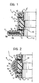
- Figure 1 is a partial section of a suture ring for a mitral valve prosthesis formed according to the invention,
- Figure 2 is also a partial section showing the structure of a suture ring for an aortic valve prosthesis formed according to the present invention.
- In the drawings, a suture ring for heart valve prostheses is generally indicated 1.
- In general terms and according to widely known principles, the ring in question is constituted substantially by a more or less flexible and resilient annular body which is intended to be fitted around the stent or housing of the valve prosthesis, not shown in the drawings, which supports the obturator means of the valve (pivoting obturators, etc.).
- The function of the suture ring is essentially to provide for and to stimulate the firm anchorage of the prosthesis in its implant position. The prosthesis in question may either be of the mechanical type with pivoting obturators or of the type with natural valve flaps.
- In general terms, the suture ring 1 can be seen to include:
- a
core 2 of rigid or semirigid material (for example, a paraformaldehyde polymer - also known by the trade name of Delrin) preferably formed according to the criteria which are the subject of a parallel patent application filed on even date by the present Applicant, and - an outer covering layer constituted essentially by a fabric of biocompatible synthetic yarn; in the solution according to the invention, this outer covering is constituted by several layers or sheets of different fabrics, indicated 3 and 4, whose characteristics will be described further below.
- In the suture ring of Figure 1, which is intended to be fitted to a mitral valve prosthesis, an external loop is formed in the
covering layer core 2 and contains an annular mass of generally soft padding formed by several, for example, three, superposedlayers - In the suture ring of Figure 2, which is intended to be fitted to an aortic valve prosthesis, a loop is formed in the
covering layer core 2; this loop also contains a mass of soft padding having a structure with several, for example, three,layers - According to widely known criteria which do not need to be repeated herein, surgical stitches are intended to extend through the external loops of the suture rings and their padding to keep the suture ring (and hence the prosthesis) securely in its desired implant position.
- The main characteristic of the suture ring according to the invention is the selection of different materials for covering the surface 7 over which the blood passing through the axial orifice in the prosthesis is intended to flow when the prosthesis is in use, and for covering the surface 8 which is intended to be exposed to the tissue to which the prosthesis is sutured.
- In the solution according to the invention, the surface 7 is covered by a
material 3 which is preferably constituted by a fabric of a substantially water-repellent synthetic material so that it absorbs substantially no blood and has little haemolytic effect. - According to a solution currently preferred by the Applicant, the
material 3 is constituted by a polytetrafluoroethylene (Teflon) fabric, preferably of the type currently known in the art as "light Teflon". - In the suture ring of Figure 1 (the mitral prosthesis), the water-
repellent material 3 extends mainly along the edge of thecore 2 of the ring and along the side of the suture loop at the end of the ring which is intended to be oriented upstream with respect to the blood flow through the prosthesis (the so-called "inflow" end); in other words, this is the end of the prosthesis over which the blood is intended to flow in use. - The second covering
layer 4 of hydrophilic, porous material, however, extends from the opposite side of the suture loop over the entire outer surface of thecore 2 and forms a turned-back portion 3′ facing the internal surface of thecore 2 of the suture ring. - The covering
layer 4 is preferably made of polyethylene terephthalate (Dacron) with a velvety structure of the type currently known in the art as "double velour". - This is a fabric whose structure is such as to encourage the colonisation of the suture ring by some of the tissue surrounding it.
- To advantage, both the covering
layer 3 and the turned-back portion 3′ are coated with a biocompatible carbon material preferably produced according to the criteria described in European patent applications Nos. 0 102 328 and 0 224 080, both in the name of the present Applicant. - This coating improves the biocompatibility of the material to which it is applied and also modifies its behaviour to a certain extent as regards its haemocompatibility characteristics.
- This applies mainly to the internal turned-
back portion 3′ which (although its basic structure is made of the hydrophilic material of the layer 4) behaves in a substantially haemocompatible manner like thematerial 3 since it is covered by biocompatible carbon. - The wording adopted in the claims which follow, according to which the first and second covering materials differ from each other, is therefore intended to mean that the two materials in question behave differently with respect to the mass of blood and to body tissue. This different behaviour may result either from the different chemical natures of their basic constituents or, as in the case of the turned-
back portion 3′, from a particular treatment which modifies the behaviour of the basic material. - As regards the structure of the mass of
padding 5a-5c of the external loop of the suture ring of Figure 1, the Applicant has found that the use of a material substantially similar to that used for the outer covering layer 4 (that is, polyethylene terephthalate) is particularly advantageous for thefirst layer 5a behind the first coveringlayer 3. Without wishing to be bound by any specific theory in this connection, he has reason to believe that the presence of the polyethylene terephthalate of thelayer 5a contributes to the formation and firm retention of a proteinaceous layer on the outer coveringlayer 3 during the period after the implantation of the prosthesis. The presence of this proteinaceous layer has been found to be particularly beneficial in minimising the chance of the prosthesis giving rise to thromboembolic complications. - The use of a felt of polytetraflurorethylene (that is, the material of the inner covering layer 3) has been found particularly to be advantageous for forming the
intermediate layer 5b of the padding since it has good characteristics of consistency and softness and can be penetrated easily by the surgical needles used for implanting the prosthesis. For theremaining layer 5c, it is thought preferable again to use a material just like that of theouter covering layer 4 so as further to improve its functional characteristics. - The covering
layer stitches 9 extending throughradial holes 10 in thecore 2. - The two covering
layers - The foregoing also applies substantially to the suture ring for aortic prostheses of Figure 2, except for the different arrangement of the suture loop.
- In this case, the water-
repellent layer 3 is divided into two portions which cover the opposite ends of thecore 2 and extend over most of its internal surface, leaving only a central tab-like appendage of thecore 2 free (as in the ring of Figure 1). The characteristics and function of this appendage are described in the application filed by the Applicant on even date and already referred to above. - Both parts of the covering
layer 3 of the ring of Figure 2 are coated with biocompatible material according to the European patent applications Nos. 0 102 328 and 0 224 080 already cited above. - As regards the outer mass of padding, the sequence of
layers 5a-5c given above is repeated for the layers 6a-6c. - The outermost layer 6a is thus made of a hydrophilic, porous material (Dacron) which improves the characteristics of the
outer layer 4 that encourage the colonisation of the suture ring by the surrounding tissue. Theintermediate layer 6b is made of polytetrafluoroethylene felt which is bulky and can be penetrated easily by surgical needles. Theinnermost layer 6c is made of a material identical to that of the outer layer 6a. In this embodiment also, the covering layer is anchored to thecore 2 by stitching 9 through theapertures 10 in thecore 2. - The padding of the suture loop may, however, have a layered structure including a different number of layers (for example, only two layers, the
innermost layer 6c in the prosthesis of Figure 2 being omitted). - Naturally, the principle of the invention remaining the same, the details of construction and forms of embodiment may be varied widely with respect to those described and illustrated, without thereby departing from the scope of the present invention.
Claims (9)
- A suture ring (1) for heart valve prostheses having a first surface (7) which is intended to be exposed to the blood flow and a second surface (8) which is intended to be exposed to the tissue to which the prosthesis is sutured, characterised in that:- the first (7) and second (8) surfaces have respective coverings of a first material (3, 3′) and a second material (4) which differ from each other,- the first material (3, 3′) covering the first surface (7) is a substantially haemocompatible material so that it absorbs substantially no blood and has little haemolytic and thrombogenic effect, and- the second material (4) covering the second surface (8) is a substantial ly hydrophilic, porous material so as to encourage the colonisation of the ring (1) by some of the tissue.
- A suture ring according to Claim 1, characterised in that at least part (3′) of one (3) of the first and second materials is made of a basic constituent identical to the basic component of the other (4) of the first and second materials, and in that at least the said part (3′) is treated to make it substantially similar to the one (3) of the first and second materials.
- A suture ring according to Claim 1, characterised in that the first (3, 3′) and second (4) materials are woven materials.
- A suture ring according to any one of Claims 1 to 3, characterised in that the first material (3) is polytetrafluoroethylene (Teflon).
- A suture ring according to any one of Claims 1 to 4, characterised in that the first material (3, 3′) has a surface coating of a biocompatible carbon material.
- A suture ring according to any one of Claims 1 to 5, characterised in that the second material is polyethylene terephthalate (Dacron).
- A suture ring according to any one of the preceding claims, characterised in that the second material has a velvety appearance.
- A suture ring according to any one of the preceding claims, characterised in that it includes an external suture loop with a layered mass of padding (5a, 5b, 5c; 6a, 6b, 6c) in a generally sandwich-like configuration with an inner layer (5b, 6b) of a material substantially like the first material and at least one outer layer (5a, 5c; 6a, 6c) of a material substantially like the second material (4).
- A suture ring according to Claim 8, particularly for mitral valve prostheses, in which the external loop has an end surface over which the blood is intended to flow, characterised in that:- the end surface is covered by the first material (3), and- the mass of padding includes a layer (5a) of a material substantially like the second material (4) behind the end surface which is covered by the first material (3).
Priority Applications (1)
| Application Number | Priority Date | Filing Date | Title |
|---|---|---|---|
| AT91830057T ATE103162T1 (en) | 1990-02-21 | 1991-02-20 | SEWING RING FOR HEART VALVE PROSTHESES. |
Applications Claiming Priority (2)
| Application Number | Priority Date | Filing Date | Title |
|---|---|---|---|
| IT6712790 | 1990-02-21 | ||
| IT67127A IT1240111B (en) | 1990-02-21 | 1990-02-21 | SUTURE RING FOR CARDIAC VALVE PROSTHESES |
Publications (2)
| Publication Number | Publication Date |
|---|---|
| EP0443993A1 true EP0443993A1 (en) | 1991-08-28 |
| EP0443993B1 EP0443993B1 (en) | 1994-03-23 |
Family
ID=11299812
Family Applications (1)
| Application Number | Title | Priority Date | Filing Date |
|---|---|---|---|
| EP91830057A Expired - Lifetime EP0443993B1 (en) | 1990-02-21 | 1991-02-20 | A suture ring for heart valve prostheses |
Country Status (6)
| Country | Link |
|---|---|
| US (1) | US5163954A (en) |
| EP (1) | EP0443993B1 (en) |
| AT (1) | ATE103162T1 (en) |
| DE (1) | DE69101458T2 (en) |
| ES (1) | ES2050521T3 (en) |
| IT (1) | IT1240111B (en) |
Cited By (3)
| Publication number | Priority date | Publication date | Assignee | Title |
|---|---|---|---|---|
| WO1996030060A1 (en) * | 1995-03-28 | 1996-10-03 | Aortech Europe Ltd. | Medical device treated with a hydrophilic polymer composition |
| US5715018A (en) * | 1992-04-10 | 1998-02-03 | Avid Technology, Inc. | Digital advertisement insertion system |
| EP1549257A4 (en) * | 2002-10-10 | 2006-09-06 | Cleveland Clinic Foundation | Method and apparatus for replacing a mitral valve with a stentless bioprosthetic valve |
Families Citing this family (80)
| Publication number | Priority date | Publication date | Assignee | Title |
|---|---|---|---|---|
| US5258023A (en) * | 1992-02-12 | 1993-11-02 | Reger Medical Development, Inc. | Prosthetic heart valve |
| US5397346A (en) * | 1992-04-28 | 1995-03-14 | Carbomedics, Inc. | Prosthetic heart valve with sewing ring |
| US5676651A (en) * | 1992-08-06 | 1997-10-14 | Electric Boat Corporation | Surgically implantable pump arrangement and method for pumping body fluids |
| US5333559A (en) * | 1992-09-14 | 1994-08-02 | Hiniker Company | Row crop cultivator and seeding attachment |
| US5397348A (en) * | 1993-12-13 | 1995-03-14 | Carbomedics, Inc. | Mechanical heart valve with compressible stiffening ring |
| DE69431122T2 (en) * | 1993-12-22 | 2003-03-27 | St. Jude Medical, Inc. | HEART VALVE HOLDER |
| US5554184A (en) * | 1994-07-27 | 1996-09-10 | Machiraju; Venkat R. | Heart valve |
| WO1996040011A1 (en) * | 1995-06-07 | 1996-12-19 | St. Jude Medical, Inc. | Direct suture orifice for mechanical heart valve |
| US5807405A (en) * | 1995-09-11 | 1998-09-15 | St. Jude Medical, Inc. | Apparatus for attachment of heart valve holder to heart valve prosthesis |
| US5713952A (en) * | 1995-09-11 | 1998-02-03 | St. Jude Medical, Inc. | Apparatus for attachment of heart valve holder to heart valve prosthesis |
| US5628789A (en) * | 1995-09-11 | 1997-05-13 | St. Jude Medical, Inc. | Apparatus for attachment of heart valve holder to heart valve prosthesis |
| US5735842A (en) * | 1995-09-11 | 1998-04-07 | St. Jude Medical, Inc. | Low profile manipulators for heart valve prostheses |
| US5814101A (en) * | 1996-09-25 | 1998-09-29 | St. Jude Medical, Inc. | Holder for heart valve prosthesis |
| US7722667B1 (en) | 1998-04-20 | 2010-05-25 | St. Jude Medical, Inc. | Two piece bioprosthetic heart valve with matching outer frame and inner valve |
| US6074418A (en) | 1998-04-20 | 2000-06-13 | St. Jude Medical, Inc. | Driver tool for heart valve prosthesis fasteners |
| US6176877B1 (en) | 1998-04-20 | 2001-01-23 | St. Jude Medical, Inc. | Two piece prosthetic heart valve |
| US6250308B1 (en) | 1998-06-16 | 2001-06-26 | Cardiac Concepts, Inc. | Mitral valve annuloplasty ring and method of implanting |
| US6066160A (en) * | 1998-11-23 | 2000-05-23 | Quickie Llc | Passive knotless suture terminator for use in minimally invasive surgery and to facilitate standard tissue securing |
| US6468305B1 (en) | 2000-05-16 | 2002-10-22 | St. Jude Medical, Inc. | Two piece valve |
| US7201771B2 (en) | 2001-12-27 | 2007-04-10 | Arbor Surgical Technologies, Inc. | Bioprosthetic heart valve |
| US7959674B2 (en) | 2002-07-16 | 2011-06-14 | Medtronic, Inc. | Suture locking assembly and method of use |
| US20060195182A1 (en) * | 2002-10-10 | 2006-08-31 | Navia Jose L | Method and apparatus for replacing a mitral valve with a stentless bioprosthetic valve |
| US8551162B2 (en) | 2002-12-20 | 2013-10-08 | Medtronic, Inc. | Biologically implantable prosthesis |
| US8021421B2 (en) | 2003-08-22 | 2011-09-20 | Medtronic, Inc. | Prosthesis heart valve fixturing device |
| US7556647B2 (en) | 2003-10-08 | 2009-07-07 | Arbor Surgical Technologies, Inc. | Attachment device and methods of using the same |
| US20070038294A1 (en) * | 2004-01-21 | 2007-02-15 | Navia Jose L | Method and apparatus for replacing a mitral valve and an aortic valve with a homograft |
| US7488346B2 (en) * | 2004-01-21 | 2009-02-10 | The Cleveland Clinic Foundation | Method and apparatus for replacing a mitral valve and an aortic valve with a single homograft |
| AU2005218326A1 (en) | 2004-02-27 | 2005-09-15 | Aortx, Inc. | Prosthetic heart valve delivery systems and methods |
| ITTO20040135A1 (en) | 2004-03-03 | 2004-06-03 | Sorin Biomedica Cardio Spa | CARDIAC VALVE PROSTHESIS |
| US8298290B2 (en) * | 2004-09-20 | 2012-10-30 | Davol, Inc. | Implantable prosthesis for soft tissue repair |
| ITTO20050074A1 (en) | 2005-02-10 | 2006-08-11 | Sorin Biomedica Cardio Srl | CARDIAC VALVE PROSTHESIS |
| US7513909B2 (en) | 2005-04-08 | 2009-04-07 | Arbor Surgical Technologies, Inc. | Two-piece prosthetic valves with snap-in connection and methods for use |
| US8211169B2 (en) | 2005-05-27 | 2012-07-03 | Medtronic, Inc. | Gasket with collar for prosthetic heart valves and methods for using them |
| US7967857B2 (en) | 2006-01-27 | 2011-06-28 | Medtronic, Inc. | Gasket with spring collar for prosthetic heart valves and methods for making and using them |
| CA2636105C (en) * | 2006-01-27 | 2015-05-05 | Circulite, Inc | Heart assist system |
| US8403981B2 (en) | 2006-02-27 | 2013-03-26 | CardiacMC, Inc. | Methods and devices for delivery of prosthetic heart valves and other prosthetics |
| US8147541B2 (en) | 2006-02-27 | 2012-04-03 | Aortx, Inc. | Methods and devices for delivery of prosthetic heart valves and other prosthetics |
| EP2023860A2 (en) | 2006-04-29 | 2009-02-18 | Arbor Surgical Technologies, Inc. | Multiple component prosthetic heart valve assemblies and apparatus and methods for delivering them |
| US8585594B2 (en) | 2006-05-24 | 2013-11-19 | Phoenix Biomedical, Inc. | Methods of assessing inner surfaces of body lumens or organs |
| JP2009540955A (en) | 2006-06-20 | 2009-11-26 | エーオーテックス, インコーポレイテッド | Artificial heart valves, support structures, and systems and methods for implanting them |
| JP2009540952A (en) | 2006-06-20 | 2009-11-26 | エーオーテックス, インコーポレイテッド | Torque shaft and torque drive |
| JP2009540956A (en) | 2006-06-21 | 2009-11-26 | エーオーテックス, インコーポレイテッド | Prosthetic valve implantation system |
| EP2650029B1 (en) * | 2006-08-30 | 2015-01-14 | CircuLite, Inc. | Devices and systems for establishing supplemental blood flow in the circulatory system |
| US8333686B2 (en) * | 2006-08-30 | 2012-12-18 | Circulite, Inc. | Cannula insertion devices, systems, and methods including a compressible member |
| US7905823B2 (en) * | 2006-08-30 | 2011-03-15 | Circulite, Inc. | Devices, methods and systems for establishing supplemental blood flow in the circulatory system |
| EP2061531B1 (en) * | 2006-09-14 | 2016-04-13 | CircuLite, Inc. | Intravascular blood pump and catheter |
| ES2400307T3 (en) * | 2007-07-19 | 2013-04-09 | Circulite, Inc. | Cannula for implantation in cardiac chamber and related systems and methods |
| US9848981B2 (en) | 2007-10-12 | 2017-12-26 | Mayo Foundation For Medical Education And Research | Expandable valve prosthesis with sealing mechanism |
| US8343029B2 (en) * | 2007-10-24 | 2013-01-01 | Circulite, Inc. | Transseptal cannula, tip, delivery system, and method |
| ATE554731T1 (en) | 2008-05-16 | 2012-05-15 | Sorin Biomedica Cardio Srl | ATRAAUMATIC PROSTHETIC HEART VALVE PROSTHESIS |
| US8845715B2 (en) * | 2008-08-18 | 2014-09-30 | Hisham M. F. SHERIF | Total aortic arch reconstruction graft |
| US20100152844A1 (en) | 2008-12-15 | 2010-06-17 | Couetil Jean-Paul A | Annuloplasty ring with directional flexibilities and rigidities to assist the mitral annulus dynamics |
| ES2551694T3 (en) | 2008-12-23 | 2015-11-23 | Sorin Group Italia S.R.L. | Expandable prosthetic valve with anchoring appendages |
| US20100249491A1 (en) * | 2009-03-27 | 2010-09-30 | Circulite, Inc. | Two-piece transseptal cannula, delivery system, and method of delivery |
| US8460168B2 (en) * | 2009-03-27 | 2013-06-11 | Circulite, Inc. | Transseptal cannula device, coaxial balloon delivery device, and methods of using the same |
| EP2628465A1 (en) * | 2009-04-27 | 2013-08-21 | Sorin Group Italia S.r.l. | Prosthetic vascular conduit |
| US8808369B2 (en) | 2009-10-05 | 2014-08-19 | Mayo Foundation For Medical Education And Research | Minimally invasive aortic valve replacement |
| US20110112353A1 (en) * | 2009-11-09 | 2011-05-12 | Circulite, Inc. | Bifurcated outflow cannulae |
| IT1400327B1 (en) | 2010-05-21 | 2013-05-24 | Sorin Biomedica Cardio Srl | SUPPORT DEVICE FOR VALVULAR PROSTHESIS AND CORRESPONDING CORRESPONDENT. |
| CN103228300A (en) | 2010-09-07 | 2013-07-31 | 保罗·A·斯彭斯 | Intubation Systems and Methods |
| ES2641902T3 (en) | 2011-02-14 | 2017-11-14 | Sorin Group Italia S.R.L. | Sutureless anchoring device for cardiac valve prostheses |
| EP2486894B1 (en) | 2011-02-14 | 2021-06-09 | Sorin Group Italia S.r.l. | Sutureless anchoring device for cardiac valve prostheses |
| US8968336B2 (en) | 2011-12-07 | 2015-03-03 | Edwards Lifesciences Corporation | Self-cinching surgical clips and delivery system |
| US9017347B2 (en) | 2011-12-22 | 2015-04-28 | Edwards Lifesciences Corporation | Suture clip deployment devices |
| EP2609893B1 (en) | 2011-12-29 | 2014-09-03 | Sorin Group Italia S.r.l. | A kit for implanting prosthetic vascular conduits |
| US9498202B2 (en) | 2012-07-10 | 2016-11-22 | Edwards Lifesciences Corporation | Suture securement devices |
| US10016193B2 (en) | 2013-11-18 | 2018-07-10 | Edwards Lifesciences Ag | Multiple-firing crimp device and methods for using and manufacturing same |
| EP2908880B1 (en) | 2012-10-16 | 2018-12-05 | Paul A. Spence | Devices for facilitating flow from the heart to a blood pump |
| US9592047B2 (en) | 2012-12-21 | 2017-03-14 | Edwards Lifesciences Corporation | System for securing sutures |
| WO2015006739A1 (en) | 2013-07-11 | 2015-01-15 | Edwards Lifesciences Corporation | Knotless suture fastener installation system |
| US9808283B2 (en) | 2013-12-04 | 2017-11-07 | Heartware, Inc. | Apparatus and methods for cutting an atrial wall |
| US10786244B2 (en) | 2014-05-30 | 2020-09-29 | Edwards Lifesciences Corporation | Systems for securing sutures |
| CR20170265A (en) | 2014-12-10 | 2017-11-17 | Edwards Lifesciences Ag | MULTIPLE REACTIVATION HOLDING DEVICE AND METHODS FOR USE AND MANUFACTURING |
| CN107106162B (en) | 2014-12-24 | 2020-10-27 | 爱德华兹生命科学公司 | Suture clip deployment device |
| US10470759B2 (en) | 2015-03-16 | 2019-11-12 | Edwards Lifesciences Corporation | Suture securement devices |
| US10939905B2 (en) | 2016-08-26 | 2021-03-09 | Edwards Lifesciences Corporation | Suture clips, deployment devices therefor, and methods of use |
| US10863980B2 (en) | 2016-12-28 | 2020-12-15 | Edwards Lifesciences Corporation | Suture fastener having spaced-apart layers |
| US12318289B2 (en) | 2018-05-23 | 2025-06-03 | Corcym S.R.L. | Device for the in-situ delivery of heart valve prosthesis |
| WO2019224577A1 (en) | 2018-05-23 | 2019-11-28 | Sorin Group Italia S.R.L. | A cardiac valve prosthesis |
| US12544226B2 (en) * | 2019-02-14 | 2026-02-10 | 4C Medical Technologies, Inc. | Hydrophilic skirt for paravalvular leak mitigation and fit and apposition optimization for prosthetic heart valve implants |
Citations (2)
| Publication number | Priority date | Publication date | Assignee | Title |
|---|---|---|---|---|
| DE1491148B1 (en) * | 1964-12-18 | 1970-12-03 | American Hospital Supply Corp | Sewing ring for heart valve prostheses |
| US3996623A (en) * | 1974-07-30 | 1976-12-14 | Kaster Robert L | Method of implanting a prosthetic device and suturing member therefor |
Family Cites Families (6)
| Publication number | Priority date | Publication date | Assignee | Title |
|---|---|---|---|---|
| US3491376A (en) * | 1965-10-06 | 1970-01-27 | Donald P Shiley | Heart valve with separate suturing ring sub-assembly |
| US3579642A (en) * | 1968-04-15 | 1971-05-25 | Bart T Heffernan | Heart valve assembly and method of implanting in the body |
| US3689942A (en) * | 1969-11-28 | 1972-09-12 | Richard K Rapp | Prosthetic heart valve |
| US4035849A (en) * | 1975-11-17 | 1977-07-19 | William W. Angell | Heart valve stent and process for preparing a stented heart valve prosthesis |
| US4377010A (en) * | 1978-11-08 | 1983-03-22 | The Secretary Of State For Defence In Her Britannic Majesty's Government Of The United Kingdom Of Great Britain And Northern Ireland | Biocompatible material comprising a base polymer bulk graft polymerized with an ethylenically unsaturated carboxylic acid |
| US4535483A (en) * | 1983-01-17 | 1985-08-20 | Hemex, Inc. | Suture rings for heart valves |
-
1990
- 1990-02-21 IT IT67127A patent/IT1240111B/en active IP Right Grant
-
1991
- 1991-02-20 AT AT91830057T patent/ATE103162T1/en not_active IP Right Cessation
- 1991-02-20 EP EP91830057A patent/EP0443993B1/en not_active Expired - Lifetime
- 1991-02-20 DE DE69101458T patent/DE69101458T2/en not_active Expired - Lifetime
- 1991-02-20 ES ES91830057T patent/ES2050521T3/en not_active Expired - Lifetime
- 1991-02-21 US US07/658,535 patent/US5163954A/en not_active Expired - Lifetime
Patent Citations (2)
| Publication number | Priority date | Publication date | Assignee | Title |
|---|---|---|---|---|
| DE1491148B1 (en) * | 1964-12-18 | 1970-12-03 | American Hospital Supply Corp | Sewing ring for heart valve prostheses |
| US3996623A (en) * | 1974-07-30 | 1976-12-14 | Kaster Robert L | Method of implanting a prosthetic device and suturing member therefor |
Cited By (3)
| Publication number | Priority date | Publication date | Assignee | Title |
|---|---|---|---|---|
| US5715018A (en) * | 1992-04-10 | 1998-02-03 | Avid Technology, Inc. | Digital advertisement insertion system |
| WO1996030060A1 (en) * | 1995-03-28 | 1996-10-03 | Aortech Europe Ltd. | Medical device treated with a hydrophilic polymer composition |
| EP1549257A4 (en) * | 2002-10-10 | 2006-09-06 | Cleveland Clinic Foundation | Method and apparatus for replacing a mitral valve with a stentless bioprosthetic valve |
Also Published As
| Publication number | Publication date |
|---|---|
| US5163954A (en) | 1992-11-17 |
| DE69101458D1 (en) | 1994-04-28 |
| EP0443993B1 (en) | 1994-03-23 |
| ATE103162T1 (en) | 1994-04-15 |
| ES2050521T3 (en) | 1994-05-16 |
| DE69101458T2 (en) | 1994-07-14 |
| IT1240111B (en) | 1993-11-27 |
| IT9067127A0 (en) | 1990-02-21 |
| IT9067127A1 (en) | 1991-08-22 |
Similar Documents
| Publication | Publication Date | Title |
|---|---|---|
| EP0443993B1 (en) | A suture ring for heart valve prostheses | |
| US3571815A (en) | Suture ring for heart valve | |
| US5104406A (en) | Heart valve prosthesis | |
| JP3405734B2 (en) | Suture ring for pivotable prosthetic heart valve | |
| US5035709A (en) | Mechanical heart valve with compliant sewing ring | |
| EP0338994A1 (en) | Prosthetic device for the surgical correction of tricuspid insufficiency | |
| US6716241B2 (en) | Venous valve and graft combination | |
| EP0155245B1 (en) | Cardiac valve prosthesis with valve flaps of biological tissues | |
| CA2265754C (en) | Prosthetic heart valve with suturing member having non-uniform radial width | |
| US5928281A (en) | Tissue heart valves | |
| JP4928036B2 (en) | Artificial heart valve with rotating cuff | |
| US6916338B2 (en) | Synthetic leaflets for heart valve repair or replacement | |
| US6231602B1 (en) | Aortic annuloplasty ring | |
| JPS60158858A (en) | Stent for tissue valve | |
| US20190365530A1 (en) | Sealing member for prosthetic heart valve | |
| JPH0479657B2 (en) | ||
| JPS5927571B2 (en) | artificial heart valve | |
| CN113768663B (en) | Locally-enhanced valve leaflet for textile-based artificial heart valve and application thereof | |
| JP2009544415A (en) | Tissue-compatible heart valve sewing ring | |
| US3534410A (en) | Cloth covered heart valve with composite materials in the areas of ball contact | |
| CN117297839A (en) | artificial heart valve |
Legal Events
| Date | Code | Title | Description |
|---|---|---|---|
| PUAI | Public reference made under article 153(3) epc to a published international application that has entered the european phase |
Free format text: ORIGINAL CODE: 0009012 |
|
| AK | Designated contracting states |
Kind code of ref document: A1 Designated state(s): AT BE CH DE DK ES FR GB GR IT LI LU NL SE |
|
| 17P | Request for examination filed |
Effective date: 19920206 |
|
| 17Q | First examination report despatched |
Effective date: 19930511 |
|
| GRAA | (expected) grant |
Free format text: ORIGINAL CODE: 0009210 |
|
| AK | Designated contracting states |
Kind code of ref document: B1 Designated state(s): AT BE CH DE DK ES FR GB GR IT LI LU NL SE |
|
| PG25 | Lapsed in a contracting state [announced via postgrant information from national office to epo] |
Ref country code: IT Free format text: LAPSE BECAUSE OF FAILURE TO SUBMIT A TRANSLATION OF THE DESCRIPTION OR TO PAY THE FEE WITHIN THE PRESCRIBED TIME-LIMIT;WARNING: LAPSES OF ITALIAN PATENTS WITH EFFECTIVE DATE BEFORE 2007 MAY HAVE OCCURRED AT ANY TIME BEFORE 2007. THE CORRECT EFFECTIVE DATE MAY BE DIFFERENT FROM THE ONE RECORDED. Effective date: 19940323 Ref country code: GR Free format text: LAPSE BECAUSE OF FAILURE TO SUBMIT A TRANSLATION OF THE DESCRIPTION OR TO PAY THE FEE WITHIN THE PRESCRIBED TIME-LIMIT Effective date: 19940323 Ref country code: AT Effective date: 19940323 Ref country code: SE Free format text: THE PATENT HAS BEEN ANNULLED BY A DECISION OF A NATIONAL AUTHORITY Effective date: 19940323 Ref country code: LI Effective date: 19940323 Ref country code: DK Effective date: 19940323 Ref country code: NL Effective date: 19940323 Ref country code: CH Effective date: 19940323 Ref country code: BE Effective date: 19940323 |
|
| REF | Corresponds to: |
Ref document number: 103162 Country of ref document: AT Date of ref document: 19940415 Kind code of ref document: T |
|
| REF | Corresponds to: |
Ref document number: 69101458 Country of ref document: DE Date of ref document: 19940428 |
|
| REG | Reference to a national code |
Ref country code: CH Ref legal event code: PL |
|
| ET | Fr: translation filed | ||
| NLV1 | Nl: lapsed or annulled due to failure to fulfill the requirements of art. 29p and 29m of the patents act | ||
| PLBE | No opposition filed within time limit |
Free format text: ORIGINAL CODE: 0009261 |
|
| STAA | Information on the status of an ep patent application or granted ep patent |
Free format text: STATUS: NO OPPOSITION FILED WITHIN TIME LIMIT |
|
| PG25 | Lapsed in a contracting state [announced via postgrant information from national office to epo] |
Ref country code: LU Free format text: LAPSE BECAUSE OF NON-PAYMENT OF DUE FEES Effective date: 19950228 |
|
| 26N | No opposition filed | ||
| REG | Reference to a national code |
Ref country code: GB Ref legal event code: 732E |
|
| REG | Reference to a national code |
Ref country code: ES Ref legal event code: PC2A Owner name: SORIN BIOMEDICA CARDIO S.P.A. |
|
| REG | Reference to a national code |
Ref country code: FR Ref legal event code: TP |
|
| REG | Reference to a national code |
Ref country code: GB Ref legal event code: IF02 |
|
| PGFP | Annual fee paid to national office [announced via postgrant information from national office to epo] |
Ref country code: ES Payment date: 20100312 Year of fee payment: 20 |
|
| PGFP | Annual fee paid to national office [announced via postgrant information from national office to epo] |
Ref country code: FR Payment date: 20100223 Year of fee payment: 20 |
|
| PGFP | Annual fee paid to national office [announced via postgrant information from national office to epo] |
Ref country code: DE Payment date: 20100303 Year of fee payment: 20 Ref country code: GB Payment date: 20100202 Year of fee payment: 20 |
|
| REG | Reference to a national code |
Ref country code: DE Ref legal event code: R071 Ref document number: 69101458 Country of ref document: DE |
|
| REG | Reference to a national code |
Ref country code: GB Ref legal event code: PE20 Expiry date: 20110219 |
|
| PG25 | Lapsed in a contracting state [announced via postgrant information from national office to epo] |
Ref country code: GB Free format text: LAPSE BECAUSE OF EXPIRATION OF PROTECTION Effective date: 20110219 |
|
| REG | Reference to a national code |
Ref country code: ES Ref legal event code: FD2A Effective date: 20120511 |
|
| PG25 | Lapsed in a contracting state [announced via postgrant information from national office to epo] |
Ref country code: ES Free format text: LAPSE BECAUSE OF EXPIRATION OF PROTECTION Effective date: 20110221 |
|
| PG25 | Lapsed in a contracting state [announced via postgrant information from national office to epo] |
Ref country code: DE Free format text: LAPSE BECAUSE OF EXPIRATION OF PROTECTION Effective date: 20110220 |