EP0444030B1 - Bohrhammer - Google Patents
Bohrhammer Download PDFInfo
- Publication number
- EP0444030B1 EP0444030B1 EP89905644A EP89905644A EP0444030B1 EP 0444030 B1 EP0444030 B1 EP 0444030B1 EP 89905644 A EP89905644 A EP 89905644A EP 89905644 A EP89905644 A EP 89905644A EP 0444030 B1 EP0444030 B1 EP 0444030B1
- Authority
- EP
- European Patent Office
- Prior art keywords
- intermediate shaft
- clutch
- drilling hammer
- drilling
- hammer according
- Prior art date
- Legal status (The legal status is an assumption and is not a legal conclusion. Google has not performed a legal analysis and makes no representation as to the accuracy of the status listed.)
- Expired - Lifetime
Links
Images
Classifications
-
- B—PERFORMING OPERATIONS; TRANSPORTING
- B25—HAND TOOLS; PORTABLE POWER-DRIVEN TOOLS; MANIPULATORS
- B25D—PERCUSSIVE TOOLS
- B25D16/00—Portable percussive machines with superimposed rotation, the rotational movement of the output shaft of a motor being modified to generate axial impacts on the tool bit
- B25D16/006—Mode changers; Mechanisms connected thereto
-
- B—PERFORMING OPERATIONS; TRANSPORTING
- B25—HAND TOOLS; PORTABLE POWER-DRIVEN TOOLS; MANIPULATORS
- B25D—PERCUSSIVE TOOLS
- B25D2216/00—Details of portable percussive machines with superimposed rotation, the rotational movement of the output shaft of a motor being modified to generate axial impacts on the tool bit
- B25D2216/0007—Details of percussion or rotation modes
- B25D2216/0046—Preventing rotation
Definitions
- the invention is based on a hammer drill according to the preamble of claim 1, as is known from the operating instructions for AEG pneumatic super MFZ.
- a hammer drill is already known, which has a clutch for switching off the striking mechanism, which can be switched with the help of the intermediate shaft.
- the rotary motion constantly transferred from the motor to the tool holder cannot be switched off.
- Such a hammer is therefore simply not suitable for chiseling.
- the object of the invention is to make it possible to select the operating states of the rotary hammer with a single switch and to simplify the transmission.
- the hammer drill according to the invention with the characterizing features of claim 1 has the advantage that the rotary movement for pure impact operation can be switched off arbitrarily and in a simple manner. As a result, the hammer can operate in three different operating states: pure drilling, impact drilling and pure hitting. Thus, for example, an additional chisel attachment on the tool holder, with which the rotary drive could be switched off in previous hammers, is unnecessary for the hammer according to the invention.
- the switchover to the different operating states is carried out in a user-friendly manner by means of a single shift lever.
- a third coupling according to claims 2 and 3 is particularly advantageous, with which the tool holder can optionally be locked in a rotationally fixed manner during the impact operation or can be set in a freely rotatable state. With the tool holder locked against rotation, all chisel work can be carried out just as well as with a pure chisel hammer. Since the intermediate shaft is also fixed, no energy is lost due to unnecessary turning of parts of the percussion drive.
- Claims 4 to 6 offer the advantage that all operating states of the hammer can be set at a single switch.
- a bearing between the intermediate shaft rotating in the drilling operating states and the displacement part for axially displacing the intermediate shaft reduces wear on the switching device.
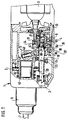
- Figure 1 shows a longitudinal section through a hammer drill according to the invention, in which the intermediate shaft is shown in different positions
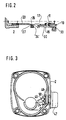
- Figure 2 shows a second embodiment in a section showing the intermediate shaft
- Figure 3 shows in cross section a switching device.
- the hammer drill 1 contains in its housing 2 essentially a motor 3, a gear 4, a striking mechanism 5 designed as an air cushion percussion mechanism and a tool holder 6 into which a tool 7 suitable for the respective application can be inserted.
- the motor 3 has a pinion 8, which is always in engagement with an outer ring gear 9 of a clutch gear 10.
- the gear wheel 10 has teeth 11 on its end face. It is under the action of a compression spring 12, which in turn is supported against an axial bearing 14 bearing against the housing part 13.
- the clutch gear 10 is rotatably supported on an intermediate shaft 17 by means of an axially displaceable needle bearing 16.
- the intermediate shaft 17 has a thickened central part 18, on the right-hand side facing the clutch gear 10 of which a counter toothing 19 is arranged, which can be coupled to the toothing 11.
- a longitudinal toothing 20 At the other end of the middle part 18 there is a longitudinal toothing 20 which, with its left end facing away from the clutch gearwheel 10, can be engaged in teeth 21 connected to the housing 2 in a manner fixed against relative rotation.
- the left end of the intermediate shaft 17 is axially displaceably mounted in a needle bearing 22 seated in the housing 2.
- a ball bearing 23 is pressed onto the middle part 18 following the longitudinal toothing 20, the outer ring of which serves as a projection 24, on which a switching device for axially displacing the intermediate shaft 17 acts.
- the inner ring of the ball bearing 21 can also be incorporated directly into the intermediate shaft 17.
- the ball bearing 21 can also be replaced by a less expensive solution with a collar 26 on the intermediate shaft 17, on which two disks 27, 28 engage. These are in turn with one Projection 24 'connected. Otherwise, the second exemplary embodiment corresponds exactly to the first in FIG. 1.
- the rotary hammer 1 comprises a movement conversion gear, which in the exemplary embodiment is designed as a wobble gear.
- a wobble hub 30 is mounted in needle bearings 31 and 32.
- the wobble hub is mounted in a ball bearing 33 designed as a fixed bearing in the housing part 13, the inner ring for the bearing 33 being formed by the wobble hub 30 itself.
- the outer ring 34 is fixed to a shoulder 35 of the housing part 13 and by a locking ring 36.
- the wobble hub 30 has a running groove 37 with an oblique axis to the axis of the intermediate shaft 17.
- the raceway 37 forms the inner raceway for a ball bearing 38, the outer ring of which is designed as a swash plate 39.
- a finger 40 formed on the swash plate 39 drives the striking mechanism 5.
- the wobble hub 10 has counter teeth 41, which can be coupled to the teeth 11 of the clutch gear 10.
- the striking mechanism 5 is guided in a tube 43 which is connected to the tool holder 6 and can be driven via a toothed wheel 44.
- the gear 44 engages in the longitudinal toothing 20 of the intermediate shaft 17 and is connected to the tube 43 via a spring-loaded safety coupling 45.
- the switching device for the intermediate shaft 17 can be seen from FIG.
- the shift lever 47 has a shaft 48 which extends through the housing 2 and has an eccentric pin 49.
- the eccentric pin engages in a fork 50 of the projection 24 or 24 'so that rotation of the shift lever 47 causes an axial displacement of the projection 24 or 24'.
- the hammer 1 can be operated in four ways.
- Figure 1 the upper half of the clutch gear 10 and the intermediate shaft 17 is shown in the drilling operating position.
- the rotational movement of the motor pinion 8 is transmitted to the intermediate shaft 17 via the clutch gear 10 and the clutch 11/19.
- the intermediate shaft 17 drives the gear 44 via its longitudinal toothing 20.
- the wobble hub 30 is not driven, the entire striking mechanism 5 and the movement conversion gear stand still.
- the safety clutch 45 serves to protect the operator. When the drill bit jams, it snaps out to prevent the hammer from turning suddenly.
- the intermediate shaft 17 is shifted further to the left until its toothing 19 is uncoupled from the toothing 11 of the clutch gearwheel.
- the clutch gear 10 cannot follow the intermediate shaft 17 because the counter-toothing 41 of the wobble hub 30 stops.
- the hammer drill is now in the chiseling operating state, the tool holder 6 still being freely rotatable. If the tool 7 is to be locked in a rotationally fixed manner, the shift lever 47 is rotated one more step until the longitudinal toothing 20 of the intermediate shaft 17 engages in the toothing 21. In this position, also called spindle lock, the hammer can be used as a full-blown chisel hammer. An overload the machine by excessive turning of the tool 7 is excluded in that the locking clutch 20/21, the safety clutch 45 is connected upstream.
Landscapes
- Engineering & Computer Science (AREA)
- Mechanical Engineering (AREA)
- Percussive Tools And Related Accessories (AREA)
- Drilling And Boring (AREA)
Applications Claiming Priority (2)
| Application Number | Priority Date | Filing Date | Title |
|---|---|---|---|
| DE3819125 | 1988-06-04 | ||
| DE3819125A DE3819125A1 (de) | 1988-06-04 | 1988-06-04 | Bohrhammer |
Publications (2)
| Publication Number | Publication Date |
|---|---|
| EP0444030A1 EP0444030A1 (de) | 1991-09-04 |
| EP0444030B1 true EP0444030B1 (de) | 1993-03-31 |
Family
ID=6355914
Family Applications (1)
| Application Number | Title | Priority Date | Filing Date |
|---|---|---|---|
| EP89905644A Expired - Lifetime EP0444030B1 (de) | 1988-06-04 | 1989-05-27 | Bohrhammer |
Country Status (4)
| Country | Link |
|---|---|
| EP (1) | EP0444030B1 (ja) |
| JP (1) | JP2703637B2 (ja) |
| DE (2) | DE3819125A1 (ja) |
| WO (1) | WO1989011955A1 (ja) |
Cited By (2)
| Publication number | Priority date | Publication date | Assignee | Title |
|---|---|---|---|---|
| WO2008064953A1 (de) * | 2006-12-01 | 2008-06-05 | Robert Bosch Gmbh | Handwerkzeugmaschine |
| DE102004020177B4 (de) | 2004-04-24 | 2024-07-18 | Robert Bosch Gmbh | Handwerkzeugmaschine mit einem drehenden und/oder schlagenden Antrieb |
Families Citing this family (16)
| Publication number | Priority date | Publication date | Assignee | Title |
|---|---|---|---|---|
| JP2828657B2 (ja) * | 1989-04-25 | 1998-11-25 | 松下電工株式会社 | ハンマードリル |
| DE3919936A1 (de) * | 1989-06-19 | 1990-12-20 | Bosch Gmbh Robert | Bohr- oder schlaghammer |
| DE3932413A1 (de) * | 1989-09-28 | 1991-04-11 | Bosch Gmbh Robert | Bohrhammer |
| DE9015285U1 (de) * | 1990-02-13 | 1991-06-06 | Kiefer, Klaus Jürgen, 2000 Hamburg | Hand-Werkzeugmaschine für mehrere Arbeits-Funktionen |
| US5025562A (en) * | 1990-03-01 | 1991-06-25 | Milwaukee Electric Tool Corporation | Counterbalanced reciprocating mechanism |
| DE4013512A1 (de) * | 1990-04-27 | 1991-10-31 | Black & Decker Inc | Schalteinrichtung zum umschalten eines kraftgetriebenen werkzeugs |
| DE19545260A1 (de) * | 1995-11-24 | 1997-05-28 | Black & Decker Inc | Bohrhammer |
| JP3582760B2 (ja) * | 1997-04-18 | 2004-10-27 | 日立工機株式会社 | ハンマドリル |
| DE102004019778B4 (de) | 2004-04-23 | 2022-04-28 | Robert Bosch Gmbh | Schaltstück |
| DE102005036731A1 (de) | 2005-08-04 | 2007-02-08 | Robert Bosch Gmbh | Kupplungsvorrichtung für eine Elektrowerkzeugmaschine und Elektrowerkzeugmaschine |
| DE102005047600A1 (de) | 2005-10-05 | 2007-04-12 | Robert Bosch Gmbh | Handwerkzeugmaschine mit einer Welle und mit einem auf der Welle gelagerten Hubantriebslager |
| DE102007001494B3 (de) | 2007-01-10 | 2008-07-10 | Aeg Electric Tools Gmbh | Handgeführter Bohrhammer |
| DE102007062248A1 (de) | 2007-12-21 | 2009-06-25 | Robert Bosch Gmbh | Handwerkzeugmaschine mit einer, mindestens eine drehbar gelagerte Zwischenwelle umfassenden Getriebevorrichtung |
| JP5181718B2 (ja) * | 2008-02-22 | 2013-04-10 | 日立工機株式会社 | ハンマドリル |
| DE102008054692A1 (de) | 2008-12-16 | 2010-06-17 | Robert Bosch Gmbh | Handwerkzeugmaschine |
| CN102975174B (zh) * | 2012-12-11 | 2015-07-08 | 浙江奔宇工具有限公司 | 电锤的传动切换装置 |
Family Cites Families (8)
| Publication number | Priority date | Publication date | Assignee | Title |
|---|---|---|---|---|
| US3837409A (en) * | 1973-02-26 | 1974-09-24 | Skil Corp | Rotary hammer power tool |
| DE2728961C2 (de) * | 1977-06-27 | 1991-08-08 | Hilti Ag, Schaan | Bohrhammer mit arretierbarem Werkzeughalter |
| DE3039669A1 (de) * | 1980-10-21 | 1982-05-27 | Robert Bosch Gmbh, 7000 Stuttgart | Bohrhammer |
| GB2121717B (en) * | 1982-06-02 | 1985-09-18 | Black & Decker Inc | Improvements in or relating to rotary percussive drills |
| DE3235400A1 (de) * | 1982-09-24 | 1984-03-29 | Licentia Patent-Verwaltungs-Gmbh, 6000 Frankfurt | Elektrowerkzeug fuer reinen bohrbetrieb, fuer schlag- oder hammerbohrbetrieb sowie fuer reinen schlagbetrieb |
| DE3329005A1 (de) * | 1983-08-11 | 1985-02-28 | Robert Bosch Gmbh, 7000 Stuttgart | Bohrhammer |
| DE3538166A1 (de) * | 1985-10-26 | 1987-04-30 | Hilti Ag | Bohrhammer mit dreharretierung |
| TWI569808B (zh) | 2014-08-15 | 2017-02-11 | 禮來大藥廠 | 肝細胞腫瘤(hcc)之治療 |
-
1988
- 1988-06-04 DE DE3819125A patent/DE3819125A1/de not_active Withdrawn
-
1989
- 1989-05-27 JP JP1505382A patent/JP2703637B2/ja not_active Expired - Lifetime
- 1989-05-27 WO PCT/DE1989/000336 patent/WO1989011955A1/de not_active Ceased
- 1989-05-27 EP EP89905644A patent/EP0444030B1/de not_active Expired - Lifetime
- 1989-05-27 DE DE8989905644T patent/DE58903984D1/de not_active Expired - Lifetime
Cited By (4)
| Publication number | Priority date | Publication date | Assignee | Title |
|---|---|---|---|---|
| DE102004020177B4 (de) | 2004-04-24 | 2024-07-18 | Robert Bosch Gmbh | Handwerkzeugmaschine mit einem drehenden und/oder schlagenden Antrieb |
| WO2008064953A1 (de) * | 2006-12-01 | 2008-06-05 | Robert Bosch Gmbh | Handwerkzeugmaschine |
| CN101541481B (zh) * | 2006-12-01 | 2011-04-06 | 罗伯特·博世有限公司 | 手持式工具机 |
| RU2453419C2 (ru) * | 2006-12-01 | 2012-06-20 | Роберт Бош Гмбх | Ручная машина |
Also Published As
| Publication number | Publication date |
|---|---|
| EP0444030A1 (de) | 1991-09-04 |
| DE3819125A1 (de) | 1989-12-14 |
| JP2703637B2 (ja) | 1998-01-26 |
| WO1989011955A1 (fr) | 1989-12-14 |
| DE58903984D1 (de) | 1993-05-06 |
| JPH03504697A (ja) | 1991-10-17 |
Similar Documents
| Publication | Publication Date | Title |
|---|---|---|
| EP0444030B1 (de) | Bohrhammer | |
| EP0564624B1 (de) | Bohrhammer | |
| DE60302283T2 (de) | Bohrhammer mit Überlastkupplung | |
| EP0221009B1 (de) | Bohrhammer mit Dreharretierung | |
| DE60127471T2 (de) | Mechanismus für Nockenantrieb | |
| EP0050192B1 (de) | Bohrhammer | |
| EP1170096B1 (de) | Kombiniertes Elektrohandwerkzeuggerät | |
| DE10205030A1 (de) | Betriebsmodi-Schalteinheit einer Handwerkzeugmaschine | |
| EP0463416B1 (de) | Elektrische Schlagbohrmaschine | |
| EP2097225B1 (de) | Handwerkzeugmaschine | |
| DE69400644T2 (de) | Motorisch angetriebenes Werkzeug, insbesondere ein Elektrowerkzeug | |
| CH627117A5 (ja) | ||
| CH698255B1 (de) | Handwerkzeugmaschine zum Bohren, Hammerbohren oder Meisseln. | |
| WO2010072433A1 (de) | Handwerkzeugmaschine | |
| DE1948055A1 (de) | Elektrisch betriebener Bohrhammer | |
| DE102005036731A1 (de) | Kupplungsvorrichtung für eine Elektrowerkzeugmaschine und Elektrowerkzeugmaschine | |
| EP0419866B1 (de) | Bohrhammer | |
| EP3461594B1 (de) | Getriebeanordnung für eine angetriebene werkzeugmaschine | |
| DE102004055236A1 (de) | Handwerkzeugmaschine mit wählbaren Betriebarten | |
| EP3456479A1 (de) | Getriebeanordnung für eine angetriebene werkzeugmasschine | |
| EP2097224A1 (de) | Handwerkzeugmaschine | |
| EP2104594B1 (de) | Handwerkzeugmaschine | |
| CH692777A5 (de) | Elektrowerkzeugmaschine. | |
| DE3241863C2 (ja) | ||
| DE3227707A1 (de) | Schlagbohrmaschine |
Legal Events
| Date | Code | Title | Description |
|---|---|---|---|
| PUAI | Public reference made under article 153(3) epc to a published international application that has entered the european phase |
Free format text: ORIGINAL CODE: 0009012 |
|
| 17P | Request for examination filed |
Effective date: 19901102 |
|
| AK | Designated contracting states |
Kind code of ref document: A1 Designated state(s): CH DE GB LI |
|
| RAP3 | Party data changed (applicant data changed or rights of an application transferred) |
Owner name: ROBERT BOSCH GMBH |
|
| 17Q | First examination report despatched |
Effective date: 19920810 |
|
| GRAA | (expected) grant |
Free format text: ORIGINAL CODE: 0009210 |
|
| AK | Designated contracting states |
Kind code of ref document: B1 Designated state(s): CH DE GB LI |
|
| REF | Corresponds to: |
Ref document number: 58903984 Country of ref document: DE Date of ref document: 19930506 |
|
| GBT | Gb: translation of ep patent filed (gb section 77(6)(a)/1977) |
Effective date: 19930414 |
|
| K2C3 | Correction of patent specification (complete document) published |
Effective date: 19930331 |
|
| PLBE | No opposition filed within time limit |
Free format text: ORIGINAL CODE: 0009261 |
|
| STAA | Information on the status of an ep patent application or granted ep patent |
Free format text: STATUS: NO OPPOSITION FILED WITHIN TIME LIMIT |
|
| 26N | No opposition filed | ||
| REG | Reference to a national code |
Ref country code: GB Ref legal event code: IF02 |
|
| PGFP | Annual fee paid to national office [announced via postgrant information from national office to epo] |
Ref country code: CH Payment date: 20080523 Year of fee payment: 20 |
|
| PGFP | Annual fee paid to national office [announced via postgrant information from national office to epo] |
Ref country code: DE Payment date: 20080728 Year of fee payment: 20 |
|
| PGFP | Annual fee paid to national office [announced via postgrant information from national office to epo] |
Ref country code: GB Payment date: 20080522 Year of fee payment: 20 |
|
| REG | Reference to a national code |
Ref country code: CH Ref legal event code: PL |
|
| REG | Reference to a national code |
Ref country code: GB Ref legal event code: PE20 Expiry date: 20090526 |
|
| PG25 | Lapsed in a contracting state [announced via postgrant information from national office to epo] |
Ref country code: GB Free format text: LAPSE BECAUSE OF EXPIRATION OF PROTECTION Effective date: 20090526 |