EP0444155B1 - Dentales ausräumwerkzeug - Google Patents
Dentales ausräumwerkzeug Download PDFInfo
- Publication number
- EP0444155B1 EP0444155B1 EP90901201A EP90901201A EP0444155B1 EP 0444155 B1 EP0444155 B1 EP 0444155B1 EP 90901201 A EP90901201 A EP 90901201A EP 90901201 A EP90901201 A EP 90901201A EP 0444155 B1 EP0444155 B1 EP 0444155B1
- Authority
- EP
- European Patent Office
- Prior art keywords
- diameter
- cutting
- plane
- tool
- shank
- Prior art date
- Legal status (The legal status is an assumption and is not a legal conclusion. Google has not performed a legal analysis and makes no representation as to the accuracy of the status listed.)
- Expired - Lifetime
Links
Images
Classifications
-
- A—HUMAN NECESSITIES
- A61—MEDICAL OR VETERINARY SCIENCE; HYGIENE
- A61C—DENTISTRY; APPARATUS OR METHODS FOR ORAL OR DENTAL HYGIENE
- A61C3/00—Dental tools or instruments
- A61C3/02—Tooth drilling or cutting instruments; Instruments acting like a sandblast machine
Definitions
- the present invention relates to a tool for use in dentistry, and more particularly to a dental tool which provides for the forming of a bore hole by generally following the natural canal of a tooth.
- the tool can be rotated by a dental handpiece commonly used in dentistry.
- US Patent No. 453254 discloses a dental tool or reamer whose cutting end has fluted lips which are hook-shaped with rounded concave forward surfaces and convex rearward surfaces.
- US Patent No. 4661061 discloses a dental tool having a blade of substantially constant effective diameter over a significant portion of its length. Triangular facets are provided on the blade between this portion and the cutting tip.
- a dental tool for the boring out of a tooth canal following its natural curvature, the tool comprising a first holder end portion and a second cutting end portion; and an intermediate shank portion interconnecting the two end portions; the holder end portion being designed to be receivable in a dental tool holder such that the dental tool holder can rotate the dental tool; the second cutting end portion having a continuously varying effective cross sectional diameter transverse to the longitudinal axis, the effective cross sectional diameter increasing from a tip having minimum effective diameter to a plane of maximum effective cutting diameter; the shank portion having a diameter less than that of the maximum effective cutting diameter: characterised in that the effective cross-sectional diameter of the second cutting end portion reduces after the plane of maximum effective cutting diameter to a plane of reduced effective cutting diameter in the direction from the second cutting end portion to the first holder end, that the diameter of the shank portion is not greater than the reduced effective cutting diameter, that the surface of the cutting end between the tip of minimum effective diameter and the
- the dental tool of the present invention is to be used with a conventional dental tool handpiece as providing support and driving power for the dental tool.
- the drill point, or reamer is placed within the root canal opening of a reduced tooth.
- the tooth has previously been ground down to approximately the desired height above the gum line by removing broken or decayed dental material.
- the tool is held by a conventional dental handpiece and the power applied to rotate the tool in a conventional manner, pressing downwardly against the tooth to bore out a hole of the desired depth.
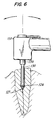
- the narrower shank permits slanting of the tool as it moves into the root canal to form the bore hole, enabling the cutting tip to generally follow the natural curvature of the tooth canal as it is pressed inwardly.
- the length of the tool is not limited to the depth of the bore hole desired.
- a separate tool can be used for counterboring and grinding, to form a desired funnel-shaped enlargement of the entrance to the bore hole, and a platform grinding tool which makes contact with the top surface of the tooth to form the desired flat platform surrounding the bore, and most preferably extending a certain distance below the surface of the surrounding tooth material.
- an anchor post for a dental prosthesis can then be inserted into the bore hole.
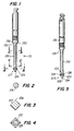
- a combination tool generally indicated by the numeral 111, is shown having a reaming, or cutting, tip, generally indicated by the numeral 127, at one end, a holder 136, at the other end, and a shank 130 therebetween.
- the holder portion 136 is of conventional design suitable for being secured to conventional dental handpieces, and can be modified or adapted for whichever dental handpiece is to be used.
- the cross-sections of the cutting sections i.e., the cutting tip 127 and the return cutting section 126, are substantially polygonal, most preferably square (as shown) or triangular, but preferably not having more than six sides, and the preferred cross-section of the shank 130 is round.
- diameter refers to the "effective diameter", i.e., the diameter of a bore hole cut by such sections rotating about a single axis.
- the cross-section views of Figures 3 and 4 shows that both portions of the routing or cutting tip 127 are substantially square in cross-section.
- the cutting tip 127 is faceted and has two sets of four facets 123, 125.
- the outer facets 125 each substantially triangular, extend from the plane of maximum diameter 129 to the tip end 128; the inner facets 123, each truncated triangles, extend from the plane of maximum diameter 129 to the beginning of the shank 130.
- Each facet in the two sets 123, 125 intersects the adjoining facet along a sharp cutting edge 124, 126, the interface 129 between the two sets of facets 123, 125 preferably is a continuous curve.
- the cutting tip 127 can be optionally coated at its apices 124, 126, or all along the facets 125, 123 as well, with a hard, fine granular material, such as diamond dust, if desired, to increase durability and reaming effectiveness.
- the tool of the present invention is located within a partially bored tooth canal, the tool is operatively supported and held by a conventional handpiece, generally indicated by the numeral 150.
- the handpiece is of a conventional type, which provides support and carries the driving power to the tool to cause it to rotate.
- the handpiece 50 can securely hold and mechanically drive the tool, while being subjected to longitudinal force axially into the tooth, during a reaming out operation.
- Such hand tools are well-known, and can, e.g., be air or motor driven, or directly gear driven, by straight or right angle dental rotary devices.
- the maximum effective diameter of the cutting tip 127 is at least about 25%, and (most) preferably at least about 40%, larger than the diameter of the shank 130.
- the shank 130 is tapered inwardly from the cutting tip to the counterbore portion 132, such that the minimum diameter of the shank is preferably just adjacent the section 136. In this manner the structurally weakest point of the tool is at the upper end of the shank 130.
- the degree of taper need only be about at least 0.5 degree and preferably about 1 degree, most at least preferably about 1.5 degrees.
- the relatively narrow shank 130 permits the cutting tip to change directions in the middle of a bore hole so as to follow the natural curvature of a tooth canal.
- curvature is relatively small, an approximately 35-50% difference in diameter is usually sufficient to permit following such curvature.
- the return cutting section 126 adjacent the shank 130, provides for cutting in the reverse direction, when withdrawing the tool. This prevents locking in of the tool in a tooth bore, and eases removal after reaming.
- a counterbore and a flat platform surface can also be formed surrounding the bore and below the top surface of the tooth.
- the maximum effective diameter of the cutting tip 127 is generally in the range of from about 0.76mm (0.03 inch) to about 2.03mm (0.08 inch), e.g. about 1.52mm (0.06 inch); the diameter of the shank is preferably about 60% to about 80% of the maximum diameter of the cutting tip 127, e.g., from about 0.64mm (0.025 inch) to about 1.32mm (0.052 inch).
- the maximum effective diameter of the counterbore is usually about 50% greater than that of the cutting tip 127, e.g., about 2.29mm (0.09 inch), and the outer diameter of the annular planar grinding surface around the counterbore is about 30% to about 50% larger again, e.g., about 3.05mm (0.12 inch).
- the tool can be formed of stainless steel, or other hard material, and coated with a fine granular abrasive, e.g., diamond dust, if desired.
- a fine granular abrasive e.g., diamond dust
Landscapes
- Health & Medical Sciences (AREA)
- Oral & Maxillofacial Surgery (AREA)
- Dentistry (AREA)
- Epidemiology (AREA)
- Life Sciences & Earth Sciences (AREA)
- Animal Behavior & Ethology (AREA)
- General Health & Medical Sciences (AREA)
- Public Health (AREA)
- Veterinary Medicine (AREA)
- Dental Tools And Instruments Or Auxiliary Dental Instruments (AREA)
Claims (8)
- Ein zahnärztliches Werkzeug zum Ausbohren eines Zahnkanals im Einklang mit dessen natürlicher Krümmung, bei dem das Werkzeug einen ersten Halterendteil (136) und einen zweiten Schneideendteil (127) sowie einen die beiden Endteile verbindenden Zwischenschaftteil (130) umfaßt; wobei der Halterendteil so konstruiert ist, daß er sich zur Aufnahme in einem Halter (150) für zahnärztliche Werkzeuge auf eine Weise eignet, die es dem Halter für zahnärztliche Werkzeuge gestattet, das zahnärztliche Werkzeug zu drehen; wobei der zweite Schneideendteil (127) quer zu der Längsachse einen kontinuierlich variierenden wirksamen Querschnittsdurchmesser aufweist und der besagte wirksame Querschnittsdurchmesser von einer Spitze (128) mit kleinstem wirksamem Durchmesser ausgehend bis zu einer Ebene zunimmt, an der der wirksame Schneidedurchmesser am größten ist; und wobei der Schaftteil (130) einen Durchmesser aufweist, der geringer ist als der größte wirksame Schneidedurchmesser:
dadurch gekennzeichnet, daß nach der Ebene mit dem größten wirksamen Schneidedurchmesser der wirksame Querschnittsdurchmesser des zweiten Schneideendteils in der Richtung von dem zweiten Schneideendteil zu dem ersten Halterende bis zu einer Ebene verringerten wirksamen Schneidedurchmessers abnimmt, daß der Durchmesser des Schaftteils nicht größer ist als der verringerte wirksame Schneidedurchmesser, daß sich die Oberfläche des Schneideendes (127) zwischen der Spitze (128) mit dem kleinsten wirksamen Durchmesser und der Ebene des größten Schneidedurchmessers aus im wesentlichen dreieckigen Facetten zusammensetzt, die sich entlang scharfer Schneidekanten schneiden, welche sich von der Ebene des größten wirksamen Durchmessers bis zu der Spitze erstrecken, sowie dadurch daß sich die Oberfläche des Schneideendes (127) zwischen der Ebene des größten Schneidedurchmessers und dem verringerten wirksamen Schneidedurchmesser aus abgestumpften Dreiecken zusammensetzt, die sich entlang scharfer, sich bis zu dem Schaftteil erstreckender Schneidekanten schneiden; wobei das Werkzeug bei Drehung innerhalb des Kanals im allgemeinen der natürlichen Krümmung des Zahnkanals folgt, was dadurch bewirkt wird, daß der Werkzeugschaft während des Ausräumens des Zahnkanals innerhalb des besagten Kanals seitlich schwenkbar ist, um den Innendurchmesser des Zahnkanals zu vergrößern. - Das zahnärztliche Werkzeug nach Anspruch 1, bei dem der Ausräumschneidequerschnitt in einer Querebene einen größten wirksamen Schneidedurchmesser aufweist.
- Das zahnärztliche Werkzeug nach Anspruch 1, bei dem ein seitlicher Querschnitt des Schaftes im wesentlichen kreisförmig ist.
- Das zahnärztliche Werkzeug nach Anspruch 1, bei dem ein seitlicher Querschnitt des Ausräumschneideabschnitts zwischen dem Bohrende und der Ebene des größten wirksamen Durchmessers die Form eines regelmäßigen Polygons hat.
- Das Werkzeug nach Anspruch 1, wobei dieses einen zwischen dem Schaft und der Ebene des größten wirksamen Durchmessers befindlichen Rückzugschneideabschnitt umfaßt, der sich in einer Richtung von der Ebene des größten Durchmessers zu dem Schaft verjüngt.
- Das Werkzeug nach Anspruch 5, bei dem ein seitlicher Querschnitt des Ausräumschneideabschnitts zwischen dem Schaft und der Ebene des größten wirksamen Schneidedurchmessers die Form eines regelmäßigen Polygons hat.
- Das Werkzeug nach Anspruch 5, bei dem die an die Ebene des größten wirksamen Durchmessers anschließenden Oberflächen eine im wesentlichen kontinuierliche Kurve beschreiben.
- Das Werkzeug nach Anspruch 1, bei dem die axial verlaufenden Schneideflächen mit relativ hartem und feinem körnigem Material beschichtete Schleifflächen sind.
Applications Claiming Priority (3)
| Application Number | Priority Date | Filing Date | Title |
|---|---|---|---|
| US27337788A | 1988-11-18 | 1988-11-18 | |
| US273377 | 1988-11-18 | ||
| PCT/US1989/005104 WO1990005498A1 (en) | 1988-11-18 | 1989-11-16 | Dental reamer tool |
Publications (3)
| Publication Number | Publication Date |
|---|---|
| EP0444155A1 EP0444155A1 (de) | 1991-09-04 |
| EP0444155A4 EP0444155A4 (en) | 1991-09-11 |
| EP0444155B1 true EP0444155B1 (de) | 1995-01-25 |
Family
ID=23043660
Family Applications (1)
| Application Number | Title | Priority Date | Filing Date |
|---|---|---|---|
| EP90901201A Expired - Lifetime EP0444155B1 (de) | 1988-11-18 | 1989-11-16 | Dentales ausräumwerkzeug |
Country Status (8)
| Country | Link |
|---|---|
| US (1) | US5017137A (de) |
| EP (1) | EP0444155B1 (de) |
| JP (1) | JPH04502870A (de) |
| AT (1) | ATE117523T1 (de) |
| AU (1) | AU4742490A (de) |
| CA (2) | CA2003176A1 (de) |
| DE (1) | DE68920885T2 (de) |
| WO (1) | WO1990005498A1 (de) |
Families Citing this family (22)
| Publication number | Priority date | Publication date | Assignee | Title |
|---|---|---|---|---|
| JP3375771B2 (ja) * | 1995-02-02 | 2003-02-10 | マニー株式会社 | ピーソーリーマ又はゲーツドリル |
| DE19536716A1 (de) * | 1995-09-30 | 1997-04-03 | Lauks Nikola | Bohrer zur Herstellung von Knochenkavitäten für zahnärztliche Implantate |
| US6106291A (en) * | 1998-12-15 | 2000-08-22 | Temple University Of The Commonwealth System Of Higher Education | Selective dentin caries excavator |
| US6347941B1 (en) | 2001-02-23 | 2002-02-19 | Temple University Of The Commonwealth System Of Higher Education | Partial dentin caries excavator |
| DE10126001A1 (de) * | 2001-05-18 | 2002-11-21 | Bock 1 Gmbh & Co | Vorgespannte Federanordnung, insbesondere zur Federbeaufschlagung von Synchronmechaniken von Bürostühlen |
| US7094055B2 (en) * | 2001-05-30 | 2006-08-22 | Steven Senia | Endodontic reamer and a method for manufacturing endodontic reamers and files |
| US7008222B2 (en) * | 2003-06-24 | 2006-03-07 | Suk Song Oh | Root canal plugging apparatus for dental work |
| US20060246394A1 (en) * | 2005-04-27 | 2006-11-02 | Giuseppe Cantatore | Endodontic files having improved lateral and torsional flexibility |
| DE102005057996B4 (de) * | 2005-12-05 | 2008-08-28 | Gebr. Brasseler Gmbh & Co. Kg | Wurzelkanalinstrument |
| ES2432412T5 (es) * | 2006-06-27 | 2020-07-22 | Straumann Holding Ag | Broca para implantología dental |
| WO2009017148A1 (ja) * | 2007-08-01 | 2009-02-05 | Mani, Inc. | ステンレススチールバー |
| DE102008010049B3 (de) * | 2008-02-20 | 2009-01-02 | Gebr. Brasseler Gmbh & Co. Kg | Dentalbohrer aus Kunststoff |
| KR100981718B1 (ko) * | 2008-06-13 | 2010-09-13 | 주식회사 메가젠임플란트 | 임플란트 시술용 드릴 |
| US20120214125A1 (en) * | 2011-02-18 | 2012-08-23 | Ss White Burs, Inc. | Endodontic burs, kits, and methods for using endodontic burs |
| DE102013000956A1 (de) * | 2013-01-21 | 2014-08-07 | Gebr. Brasseler Gmbh & Co. Kg | Schaft eines Dentalwerkzeugs |
| TWM464145U (zh) * | 2013-06-18 | 2013-11-01 | Ming-Zong Li | 用於植牙手機之鑽頭結構 |
| KR101717084B1 (ko) * | 2015-08-31 | 2017-03-20 | 주식회사 제노스 | 치아 임플란트 식립용 드릴링 드라이버 |
| DE102016111839B3 (de) * | 2016-06-28 | 2017-08-31 | Carsten Appel | Instrument zur apikalen Aufbereitung eines Wurzelkanals |
| US12220296B1 (en) | 2018-12-06 | 2025-02-11 | Gary Bram | Osteotomy drill bit to produce an optimally shaped jawbone opening for a dental implant and abutment |
| US11471172B1 (en) | 2018-12-06 | 2022-10-18 | Gary Bram | Osteotomy drill bit to produce an optimally shaped jawbone opening for a dental implant and abutment |
| USD1088228S1 (en) | 2019-12-05 | 2025-08-12 | Gary Bram | Osteotomy drill |
| US12167951B1 (en) | 2022-01-20 | 2024-12-17 | Gary Bram | Osteotomy drill bit to produce an optimally shaped jawbone opening for a dental implant and abutment |
Family Cites Families (9)
| Publication number | Priority date | Publication date | Assignee | Title |
|---|---|---|---|---|
| US453254A (en) * | 1891-06-02 | Dental drill | ||
| US1307446A (en) * | 1919-06-24 | Mathew m | ||
| US503744A (en) * | 1893-08-22 | Woodbury storer how | ||
| US1499970A (en) * | 1922-10-30 | 1924-07-01 | Bush Clarence | Pilot reamer |
| US2715772A (en) * | 1950-07-15 | 1955-08-23 | Frico G M B H | Dental burr |
| US2902763A (en) * | 1954-02-27 | 1959-09-08 | Hager & Meisinger G M B H | Dental finishing tool, especially for interproximal work |
| DE2649209A1 (de) * | 1976-10-28 | 1978-05-11 | Ellman Shirley | Zahnreinigungswerkzeug |
| US4684346A (en) * | 1985-07-22 | 1987-08-04 | Howard Martin | Endodontic access bur with extended diamond coat and method for using |
| US4661061A (en) * | 1985-07-22 | 1987-04-28 | Howard Martin | Four sided root canal rasp for root canal preparation |
-
1989
- 1989-11-16 WO PCT/US1989/005104 patent/WO1990005498A1/en not_active Ceased
- 1989-11-16 JP JP2501228A patent/JPH04502870A/ja active Pending
- 1989-11-16 EP EP90901201A patent/EP0444155B1/de not_active Expired - Lifetime
- 1989-11-16 CA CA002003176A patent/CA2003176A1/en not_active Abandoned
- 1989-11-16 AT AT90901201T patent/ATE117523T1/de not_active IP Right Cessation
- 1989-11-16 DE DE68920885T patent/DE68920885T2/de not_active Expired - Fee Related
- 1989-11-16 AU AU47424/90A patent/AU4742490A/en not_active Abandoned
- 1989-11-17 CA CA002003315A patent/CA2003315A1/en not_active Abandoned
-
1990
- 1990-09-11 US US07/580,896 patent/US5017137A/en not_active Expired - Lifetime
Also Published As
| Publication number | Publication date |
|---|---|
| JPH04502870A (ja) | 1992-05-28 |
| EP0444155A1 (de) | 1991-09-04 |
| CA2003315A1 (en) | 1990-05-18 |
| EP0444155A4 (en) | 1991-09-11 |
| CA2003176A1 (en) | 1990-05-18 |
| ATE117523T1 (de) | 1995-02-15 |
| DE68920885D1 (de) | 1995-03-09 |
| DE68920885T2 (de) | 1995-07-13 |
| AU4742490A (en) | 1990-06-12 |
| WO1990005498A1 (en) | 1990-05-31 |
| US5017137A (en) | 1991-05-21 |
Similar Documents
| Publication | Publication Date | Title |
|---|---|---|
| US5017137A (en) | Dental tool reamer capable of following natural curvature of tooth canal | |
| US4990088A (en) | Dental tool combining reamer and router | |
| US5066230A (en) | Dental product combining a reamer tool and anchor post | |
| US6419488B1 (en) | Endodontic instrument having a chisel tip | |
| US4830615A (en) | Two-grit cutting and polishing instruments | |
| EP0147419B1 (de) | Rotierende schneidespitze | |
| US5569035A (en) | Enhanced cutting drill tip for endosseous implants | |
| US5791902A (en) | Drill bit for producing bone cavities for dental implants | |
| US5938440A (en) | Endodontic instrument | |
| EP0893973B1 (de) | Endodontisches instrument | |
| US20060111724A1 (en) | Bone harvesting drill bit for oral surgery | |
| US20040126735A1 (en) | Ultrasonic microtube dental instruments and methods of using same | |
| EP1075228B1 (de) | Nichtzirkuläre endodontoische instrumente | |
| US4389192A (en) | Dental reducing tool | |
| EP1072345A3 (de) | Fräser | |
| CN113558791B (zh) | 外科手术用钻式切削工具 | |
| EP0025645A1 (de) | Reduzierendes zahnärztliches Werkzeug | |
| EP2675388B1 (de) | Endodontische bohrer und kits | |
| US4854871A (en) | Method and apparatus for providing a level surface on a tooth root | |
| CA2025237A1 (en) | Acetabulum reamer | |
| US4634379A (en) | Abrasive dental tool | |
| US4270903A (en) | Abrasive dental tool | |
| EP0895462B1 (de) | Mit einer meisselspitze ausgerüstetes endodontisches instrument | |
| KR101968421B1 (ko) | 치과용 버 | |
| KR102840164B1 (ko) | 치과용 드릴 |
Legal Events
| Date | Code | Title | Description |
|---|---|---|---|
| PUAI | Public reference made under article 153(3) epc to a published international application that has entered the european phase |
Free format text: ORIGINAL CODE: 0009012 |
|
| 17P | Request for examination filed |
Effective date: 19910514 |
|
| AK | Designated contracting states |
Kind code of ref document: A1 Designated state(s): AT BE CH DE FR GB IT LI LU NL SE |
|
| A4 | Supplementary search report drawn up and despatched |
Effective date: 19910722 |
|
| AK | Designated contracting states |
Kind code of ref document: A4 Designated state(s): AT BE CH DE FR GB IT LI LU NL SE |
|
| 17Q | First examination report despatched |
Effective date: 19930210 |
|
| GRAA | (expected) grant |
Free format text: ORIGINAL CODE: 0009210 |
|
| AK | Designated contracting states |
Kind code of ref document: B1 Designated state(s): AT BE CH DE FR GB IT LI LU NL SE |
|
| PG25 | Lapsed in a contracting state [announced via postgrant information from national office to epo] |
Ref country code: NL Effective date: 19950125 Ref country code: BE Effective date: 19950125 Ref country code: AT Effective date: 19950125 |
|
| REF | Corresponds to: |
Ref document number: 117523 Country of ref document: AT Date of ref document: 19950215 Kind code of ref document: T |
|
| REF | Corresponds to: |
Ref document number: 68920885 Country of ref document: DE Date of ref document: 19950309 |
|
| ITF | It: translation for a ep patent filed | ||
| ET | Fr: translation filed | ||
| NLV1 | Nl: lapsed or annulled due to failure to fulfill the requirements of art. 29p and 29m of the patents act | ||
| PLBE | No opposition filed within time limit |
Free format text: ORIGINAL CODE: 0009261 |
|
| STAA | Information on the status of an ep patent application or granted ep patent |
Free format text: STATUS: NO OPPOSITION FILED WITHIN TIME LIMIT |
|
| PG25 | Lapsed in a contracting state [announced via postgrant information from national office to epo] |
Ref country code: LU Free format text: LAPSE BECAUSE OF NON-PAYMENT OF DUE FEES Effective date: 19951130 |
|
| 26N | No opposition filed | ||
| PGFP | Annual fee paid to national office [announced via postgrant information from national office to epo] |
Ref country code: GB Payment date: 19961114 Year of fee payment: 8 |
|
| PGFP | Annual fee paid to national office [announced via postgrant information from national office to epo] |
Ref country code: FR Payment date: 19961126 Year of fee payment: 8 |
|
| PG25 | Lapsed in a contracting state [announced via postgrant information from national office to epo] |
Ref country code: GB Free format text: LAPSE BECAUSE OF NON-PAYMENT OF DUE FEES Effective date: 19971116 |
|
| PGFP | Annual fee paid to national office [announced via postgrant information from national office to epo] |
Ref country code: SE Payment date: 19971117 Year of fee payment: 9 |
|
| PGFP | Annual fee paid to national office [announced via postgrant information from national office to epo] |
Ref country code: DE Payment date: 19971121 Year of fee payment: 9 |
|
| PG25 | Lapsed in a contracting state [announced via postgrant information from national office to epo] |
Ref country code: FR Free format text: THE PATENT HAS BEEN ANNULLED BY A DECISION OF A NATIONAL AUTHORITY Effective date: 19971130 |
|
| PGFP | Annual fee paid to national office [announced via postgrant information from national office to epo] |
Ref country code: CH Payment date: 19971208 Year of fee payment: 9 |
|
| GBPC | Gb: european patent ceased through non-payment of renewal fee |
Effective date: 19971116 |
|
| REG | Reference to a national code |
Ref country code: FR Ref legal event code: ST |
|
| PG25 | Lapsed in a contracting state [announced via postgrant information from national office to epo] |
Ref country code: SE Free format text: LAPSE BECAUSE OF NON-PAYMENT OF DUE FEES Effective date: 19981117 |
|
| PG25 | Lapsed in a contracting state [announced via postgrant information from national office to epo] |
Ref country code: LI Free format text: LAPSE BECAUSE OF NON-PAYMENT OF DUE FEES Effective date: 19981130 Ref country code: CH Free format text: LAPSE BECAUSE OF NON-PAYMENT OF DUE FEES Effective date: 19981130 |
|
| REG | Reference to a national code |
Ref country code: CH Ref legal event code: PL |
|
| EUG | Se: european patent has lapsed |
Ref document number: 90901201.5 |
|
| PG25 | Lapsed in a contracting state [announced via postgrant information from national office to epo] |
Ref country code: DE Free format text: LAPSE BECAUSE OF NON-PAYMENT OF DUE FEES Effective date: 19990901 |
|
| PG25 | Lapsed in a contracting state [announced via postgrant information from national office to epo] |
Ref country code: IT Free format text: LAPSE BECAUSE OF NON-PAYMENT OF DUE FEES Effective date: 20051116 |