EP0444255A1 - Support de tambour pour manipuler, emmagasiner et transporter des câbles, notamment des câbles en fil métallique - Google Patents
Support de tambour pour manipuler, emmagasiner et transporter des câbles, notamment des câbles en fil métallique Download PDFInfo
- Publication number
- EP0444255A1 EP0444255A1 EP90122909A EP90122909A EP0444255A1 EP 0444255 A1 EP0444255 A1 EP 0444255A1 EP 90122909 A EP90122909 A EP 90122909A EP 90122909 A EP90122909 A EP 90122909A EP 0444255 A1 EP0444255 A1 EP 0444255A1
- Authority
- EP
- European Patent Office
- Prior art keywords
- bearing
- brake
- reel
- rope
- hub
- Prior art date
- Legal status (The legal status is an assumption and is not a legal conclusion. Google has not performed a legal analysis and makes no representation as to the accuracy of the status listed.)
- Granted
Links
- 238000004804 winding Methods 0.000 claims abstract description 29
- 230000000694 effects Effects 0.000 claims abstract description 13
- 210000000078 claw Anatomy 0.000 claims description 16
- 125000006850 spacer group Chemical group 0.000 claims description 7
- 230000006835 compression Effects 0.000 claims description 6
- 238000007906 compression Methods 0.000 claims description 6
- 238000003780 insertion Methods 0.000 claims description 3
- 230000037431 insertion Effects 0.000 claims description 3
- 230000015572 biosynthetic process Effects 0.000 claims 1
- 208000027418 Wounds and injury Diseases 0.000 description 13
- 206010052428 Wound Diseases 0.000 description 10
- 230000006378 damage Effects 0.000 description 5
- 208000014674 injury Diseases 0.000 description 3
- 230000005540 biological transmission Effects 0.000 description 1
- 230000000903 blocking effect Effects 0.000 description 1
- 230000009191 jumping Effects 0.000 description 1
- 230000007257 malfunction Effects 0.000 description 1
- 238000000034 method Methods 0.000 description 1
- 230000000750 progressive effect Effects 0.000 description 1
Images


Classifications
-
- B—PERFORMING OPERATIONS; TRANSPORTING
- B65—CONVEYING; PACKING; STORING; HANDLING THIN OR FILAMENTARY MATERIAL
- B65H—HANDLING THIN OR FILAMENTARY MATERIAL, e.g. SHEETS, WEBS, CABLES
- B65H75/00—Storing webs, tapes, or filamentary material, e.g. on reels
- B65H75/02—Cores, formers, supports, or holders for coiled, wound, or folded material, e.g. reels, spindles, bobbins, cop tubes, cans, mandrels or chucks
- B65H75/34—Cores, formers, supports, or holders for coiled, wound, or folded material, e.g. reels, spindles, bobbins, cop tubes, cans, mandrels or chucks specially adapted or mounted for storing and repeatedly paying-out and re-storing lengths of material provided for particular purposes, e.g. anchored hoses, power cables
- B65H75/38—Cores, formers, supports, or holders for coiled, wound, or folded material, e.g. reels, spindles, bobbins, cop tubes, cans, mandrels or chucks specially adapted or mounted for storing and repeatedly paying-out and re-storing lengths of material provided for particular purposes, e.g. anchored hoses, power cables involving the use of a core or former internal to, and supporting, a stored package of material
- B65H75/44—Constructional details
-
- B—PERFORMING OPERATIONS; TRANSPORTING
- B65—CONVEYING; PACKING; STORING; HANDLING THIN OR FILAMENTARY MATERIAL
- B65H—HANDLING THIN OR FILAMENTARY MATERIAL, e.g. SHEETS, WEBS, CABLES
- B65H75/00—Storing webs, tapes, or filamentary material, e.g. on reels
- B65H75/02—Cores, formers, supports, or holders for coiled, wound, or folded material, e.g. reels, spindles, bobbins, cop tubes, cans, mandrels or chucks
- B65H75/34—Cores, formers, supports, or holders for coiled, wound, or folded material, e.g. reels, spindles, bobbins, cop tubes, cans, mandrels or chucks specially adapted or mounted for storing and repeatedly paying-out and re-storing lengths of material provided for particular purposes, e.g. anchored hoses, power cables
- B65H75/38—Cores, formers, supports, or holders for coiled, wound, or folded material, e.g. reels, spindles, bobbins, cop tubes, cans, mandrels or chucks specially adapted or mounted for storing and repeatedly paying-out and re-storing lengths of material provided for particular purposes, e.g. anchored hoses, power cables involving the use of a core or former internal to, and supporting, a stored package of material
- B65H75/40—Cores, formers, supports, or holders for coiled, wound, or folded material, e.g. reels, spindles, bobbins, cop tubes, cans, mandrels or chucks specially adapted or mounted for storing and repeatedly paying-out and re-storing lengths of material provided for particular purposes, e.g. anchored hoses, power cables involving the use of a core or former internal to, and supporting, a stored package of material mobile or transportable
Definitions
- the invention relates to a storage rack for rope reels for handling, storing and transporting ropes, in particular wire ropes, with a bearing axis for the rope reel.
- Simple cable reels are regularly used to handle, store and transport wire ropes, such as those used for cable bottles, cable pulling devices, motorized cables or the like.
- wire ropes For winding and unwinding the wire ropes such reels are on a makeshift axis - z.
- the invention has for its object to provide a storage rack for a cable reel of the type described above, which enables always controlled and proper winding, unwinding, storing and transporting ropes, in particular wire ropes, in a simple and functional manner.
- the invention in a generic storage rack in that the bearing axis of a bearing pin and an intermediate hub for the cable reel rotatably mounted on the bearing pin It is formed that the intermediate hub is mounted with the interposition of a ratchet with a freewheel in the winding direction and with frictional engagement between the ratchet and the intermediate hub and the resulting braking effect in the winding direction on the journal, and that a stationary rope brake is provided in the winding direction for the rope to be wound, wound or unwound .
- the intermediate hub enables the correct storage of rope reels of various designs.
- the locking mechanism ensures free running in the course of winding and locks in the course of unwinding without blocking.
- a hub brake is assigned to the locking mechanism for both directions of rotation according to a preferred embodiment of the invention. This already ensures that the respective rope, and in particular wire rope, is wound up and unwound in a proper and functional manner.
- the reel speed corresponds to the pulling speed of the rope. If the cable movement is interrupted, the reel rotation is immediately braked so that the remaining cable windings remain in their position on the cable reel. This prevents uncontrolled lifting or jumping of rope windings.
- the rope is unwound smoothly by means of the rope brake, the effect of which also prevents the rope from being pulled back, in particular with short and light ropes, to the rope reel and thus also loosening of the rope turns at a standstill.
- the rope is always slightly pretensioned by the rope brake and is thus wound on the one hand in full turns and on the other hand unwound in a controlled manner and consequently without loosening.
- a single operator is able to wind or unwind even long ropes - longer than 100 m - compactly and without twists.
- the known lightweight reels have to be operated by at least two people. The entire winding and unwinding process always harbors the risk of injury, especially with heavy ropes and hand braking.
- the bearing journal can be designed as a flying journal to make it easier to attach the cable reel.
- Various embodiments are possible as a rope reel.
- the cable reel can be firmly screwed to the intermediate hub.
- the intermediate hub preferably has a predetermined profile cross section, e.g. B. a polygonal cross-section, and a cable reel with a correspondingly hollow reel hub can be rotatably attached to the intermediate hub.
- a reel seat to the intermediate hub, e.g. B. a disc that is suitable for connecting a coiler without a reel hub.
- the invention teaches that the intermediate hub is designed as a tensioning device for reel hubs with different inner diameters, so that a perfect transmission of the braking effect from the intermediate hub to the cable reel is achieved.
- the intermediate hub has two clamping cones, of which one clamping cone is axially supported on the bearing journal in the direction of the other clamping cone and the other clamping cone by means of a clamping nut, e.g. . B.
- both clamping cones each surrounded by at least one elastic or expandable snap ring and a spacer sleeve holding the two snap rings at a predetermined distance and that the respective reel hub can be clamped on the intermediate hub by the adjustment of the other clamping cone by means of the snap rings which expand radially on the axially moving cone surfaces of both clamping cones.
- the lock is expediently designed as a ball bearing freewheel, the inner ring of which is fastened to the bearing journal and the outer ring of which engages in the axially supported clamping cone to form friction surfaces for the frictional engagement.
- the invention further teaches that the hub brake is designed as a compression spring surrounding the bearing journal, and that the compression spring is supported on the one hand against a releasable inner collar of the axially supported clamping cone, and on the other hand with the interposition of one or more spacer rings to change the braking action against the ball bearing freewheel or its outer ring is.
- the insertable spacer rings are used to adjust the spring force so that the braking effect can be influenced by adapting to the respective rope.
- the cable brake has a brake block pivotably mounted between two bearing cheeks with a given eccentricity against the rope to be wound up, wound up or unwound, and a brake claw that overlaps the brake block, that the brake block on the side facing away from its bearing axis in accordance with the eccentricity, a spring support has that the brake claw forms a cable insertion slot with a bearing cheek, which is opened when the brake block is pressed against the spring support, the brake surface of the brake block being designed such that the braking surface distance between the brake block and the brake claw increases when the cable runs in the winding direction reduced and enlarged with rope running in the unwinding direction and always smaller than the rope diameter.
- the brake block is expediently made of plastic and has a ridge-like braking surface with a crowned leg on the one hand and a wedge-like tapering leg on the other hand.
- the spherical leg narrows the braking surface distance in the course of winding the rope in question due to the pivotable mounting of the brake block, so that a progressive braking force is achieved.
- the wedge-shaped leg ensures an increasing opening of the braking surface distance, the braking surface distance however remaining smaller than the rope diameter.
- the brake claw can be designed as a U-shaped development of the one bearing cheek and is also designed with plastic to form its braking surface.
- the storage rack is characterized by a support frame with a horizontal foot frame and a vertical support profile, the support profile having an end bend with a handle and the right-angled bearing journal with an intermediate hub between the handle and the foot frame and the cable brake being arranged on the foot frame in the winding direction.
- the support frame can be formed from a tubular profile or hollow profile. As a result, a particularly light support frame for transport purposes is realized.
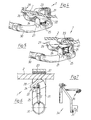
- a storage rack for rope reel 1 for handling, storing and transporting ropes 2, in particular wire ropes, is shown with a bearing axis 3 for the rope reel 1.
- the bearing axis is formed by a bearing pin 4 and an intermediate hub 5, which is rotatably mounted on the bearing pin 4, for the cable reel 1.
- the intermediate hub 5 is mounted on the journal 4 with the interposition of a ratchet 6 with a freewheel in the winding direction and with frictional engagement between the ratchet 6 and the intermediate hub 5 and the resulting braking action in the winding direction.
- a stationary rope brake 7 is provided for the rope 2 to be wound, wound or unwound.
- a hub brake 8 is assigned to the locking mechanism 6.
- the bearing pin 4 is designed as a flying pin.
- the intermediate hub 5 is designed as a clamping device for hollow reel hubs 9 with different inner diameters.
- the intermediate hub 5 has two clamping cones 10a, 10b, of which one clamping cone 10a is axially supported on the bearing journal 4 in the direction of the other clamping cone 10b and the other clamping cone 10b by means of a clamping nut 11, e.g. B. knurled nut, on a fixed in the one cone 10a and aligned with the bearing pin 4 threaded bolt 12 against the one cone 10a is adjustable.
- Both clamping cones 10a, 10b are each surrounded by at least one elastic or expandable snap ring 13 and a spacer sleeve 14 holding the two snap rings 13 at a predetermined distance.
- the respective reel hub 9 is radially widened by the adjustment of the other clamping cone 10b by means of the axially moving cone surfaces of both clamping cones Snap rings 13 can be clamped on the intermediate hub 5.
- the locking mechanism 6 is designed as a ball bearing freewheel, the inner ring 15 of which is fastened to the bearing journal 4 and the outer ring 16 of which engages in the axially supported clamping cone 10a to form friction surfaces 17 for frictional engagement.
- the hub brake 8 has a compression spring 18 surrounding the bearing pin 4 and, according to the exemplary embodiment, acts only in the unwinding direction, and thus influences the braking action resulting from the frictional engagement between the ratchet and the intermediate hub.
- the compression spring 18 is supported on the one hand against a releasable inner collar 19 of the axially supported clamping cone 10a, and on the other hand with the interposition of one or more spacer rings 20 to change the braking action against the ball bearing freewheel or its outer ring 16.
- the cable brake 7 has a brake block 22 which is pivotably mounted between two bearing cheeks 21 with a predetermined eccentricity E against the cable 2 to be wound, wound or unwound, and a brake claw 23 which overlaps the brake block 22.
- the brake block 22 has on the side facing away from its bearing axis 24 in accordance with the eccentricity E a spring support 25 made of, for example, two coil springs.
- the brake claw 23 forms with a bearing cheek 21 a cable insertion slot 26 which is opened when the brake block 22 is pressed against the spring support 25 and is otherwise closed by the brake block 22, the braking surface of the brake block 22 being designed such that the braking surface distance between the brake block 22 and Brake claw 23 is reduced when the rope 2 runs in the winding direction and when in the unwinding direction continuous rope 2 enlarged and always smaller than the rope diameter in order to always maintain braking effect.
- the brake block 22 is made of plastic and has a ridge-like braking surface with, on the one hand, a spherical leg 27 and, on the other hand, a wedge-like tapering leg 28.
- the brake claw 23 is designed as a U-shaped angling of the one bearing cheek 21.
- the bearing frame is characterized by a support frame 29 with a horizontal foot frame 30 and a vertical support profile 31, the support profile 31 having an angled end with the handle 32 and between the handle 32 and the foot frame 30 the right-angled bearing pin 4 with an intermediate hub 5.
- the cable brake 7 is arranged on the foot frame 30 in the winding direction.
- the support frame 29 is formed from a tubular profile or hollow profile. - A fold-out hand crank 34 with corresponding claws 35 and clamping devices 36 can be placed on the cable reel 1 or its spokes 33 and hubs 9.
Landscapes
- Storing, Repeated Paying-Out, And Re-Storing Of Elongated Articles (AREA)
- Storage Of Web-Like Or Filamentary Materials (AREA)
- Unwinding Of Filamentary Materials (AREA)
Priority Applications (1)
| Application Number | Priority Date | Filing Date | Title |
|---|---|---|---|
| AT90122909T ATE94146T1 (de) | 1990-02-26 | 1990-11-30 | Lagergestell fuer einen seilhaspel zum handhaben, lagern und transportieren von seilen, insbesondere drahtseilen. |
Applications Claiming Priority (2)
| Application Number | Priority Date | Filing Date | Title |
|---|---|---|---|
| DE4005787 | 1990-02-26 | ||
| DE4005787A DE4005787C1 (fr) | 1990-02-26 | 1990-02-26 |
Publications (2)
| Publication Number | Publication Date |
|---|---|
| EP0444255A1 true EP0444255A1 (fr) | 1991-09-04 |
| EP0444255B1 EP0444255B1 (fr) | 1993-09-08 |
Family
ID=6400852
Family Applications (1)
| Application Number | Title | Priority Date | Filing Date |
|---|---|---|---|
| EP90122909A Expired - Lifetime EP0444255B1 (fr) | 1990-02-26 | 1990-11-30 | Support de tambour pour manipuler, emmagasiner et transporter des câbles, notamment des câbles en fil métallique |
Country Status (3)
| Country | Link |
|---|---|
| EP (1) | EP0444255B1 (fr) |
| AT (1) | ATE94146T1 (fr) |
| DE (1) | DE4005787C1 (fr) |
Cited By (2)
| Publication number | Priority date | Publication date | Assignee | Title |
|---|---|---|---|---|
| FR2814681A1 (fr) * | 2000-10-04 | 2002-04-05 | Sm Services | Dispositif enrouleur destine plus particulierement a permettre l'enroulement de tuyaux dans le domaine de la lutte contre l'incendie |
| WO2006134181A1 (fr) * | 2005-06-13 | 2006-12-21 | SUERO CASTAÑO, María Teresa | Cadre de deroulement regule de tuyau anti-incendie |
Families Citing this family (2)
| Publication number | Priority date | Publication date | Assignee | Title |
|---|---|---|---|---|
| DE29504913U1 (de) * | 1995-03-23 | 1995-05-18 | Kästle, Arthur, 82405 Wessobrunn | Hilfseinrichtung zum Aufwickeln von Kabeln |
| DE10012457A1 (de) * | 2000-03-15 | 2001-09-20 | Adolf Wuerth Gmbh & Co Kg | Abrollgerät für Schläuche oder dergleichen |
Citations (5)
| Publication number | Priority date | Publication date | Assignee | Title |
|---|---|---|---|---|
| FR1145886A (fr) * | 1956-03-20 | 1957-10-30 | Enrouleurs Baron | Dispositif compensateur d'enroulement entièrement automatique pour câbles, tuyaux ou éléments souples analogues |
| US3395308A (en) * | 1965-10-11 | 1968-07-30 | Machinery And Welder Corp | Means for mounting a reel assembly for continuous welding |
| US4003528A (en) * | 1975-12-31 | 1977-01-18 | Booze Joe L | Mounting and braking apparatus for coiled welding wire |
| EP0017017A1 (fr) * | 1979-03-23 | 1980-10-15 | Siemens Aktiengesellschaft | Dispositif de freinage pour un tambour à câble disposé dans un boîtier |
| CH622225A5 (en) * | 1977-07-04 | 1981-03-31 | Alfred Steffen | Cable drum with holder |
Family Cites Families (1)
| Publication number | Priority date | Publication date | Assignee | Title |
|---|---|---|---|---|
| DE3324855A1 (de) * | 1983-07-09 | 1985-01-24 | Rehau Plastiks Ag + Co, 8673 Rehau | Wickeleinrichtung fuer wickelbares gut |
-
1990
- 1990-02-26 DE DE4005787A patent/DE4005787C1/de not_active Expired - Fee Related
- 1990-11-30 AT AT90122909T patent/ATE94146T1/de not_active IP Right Cessation
- 1990-11-30 EP EP90122909A patent/EP0444255B1/fr not_active Expired - Lifetime
Patent Citations (5)
| Publication number | Priority date | Publication date | Assignee | Title |
|---|---|---|---|---|
| FR1145886A (fr) * | 1956-03-20 | 1957-10-30 | Enrouleurs Baron | Dispositif compensateur d'enroulement entièrement automatique pour câbles, tuyaux ou éléments souples analogues |
| US3395308A (en) * | 1965-10-11 | 1968-07-30 | Machinery And Welder Corp | Means for mounting a reel assembly for continuous welding |
| US4003528A (en) * | 1975-12-31 | 1977-01-18 | Booze Joe L | Mounting and braking apparatus for coiled welding wire |
| CH622225A5 (en) * | 1977-07-04 | 1981-03-31 | Alfred Steffen | Cable drum with holder |
| EP0017017A1 (fr) * | 1979-03-23 | 1980-10-15 | Siemens Aktiengesellschaft | Dispositif de freinage pour un tambour à câble disposé dans un boîtier |
Cited By (2)
| Publication number | Priority date | Publication date | Assignee | Title |
|---|---|---|---|---|
| FR2814681A1 (fr) * | 2000-10-04 | 2002-04-05 | Sm Services | Dispositif enrouleur destine plus particulierement a permettre l'enroulement de tuyaux dans le domaine de la lutte contre l'incendie |
| WO2006134181A1 (fr) * | 2005-06-13 | 2006-12-21 | SUERO CASTAÑO, María Teresa | Cadre de deroulement regule de tuyau anti-incendie |
Also Published As
| Publication number | Publication date |
|---|---|
| EP0444255B1 (fr) | 1993-09-08 |
| ATE94146T1 (de) | 1993-09-15 |
| DE4005787C1 (fr) | 1991-06-13 |
Similar Documents
| Publication | Publication Date | Title |
|---|---|---|
| DE69107399T2 (de) | Aufrolleinrichtung für Rolläden. | |
| DE2900104A1 (de) | Gehaeusezusammenstellung fuer eine vorgespannte feder einer sicherheitsgurteinziehvorrichtung | |
| DE69317705T2 (de) | Spule mit Draht oder Drahtseil | |
| DE1499082A1 (de) | Vorrichtung zum Abrollen von Draht | |
| DE10158428A1 (de) | Rolloanordnung | |
| EP0444255B1 (fr) | Support de tambour pour manipuler, emmagasiner et transporter des câbles, notamment des câbles en fil métallique | |
| DE102010002052A1 (de) | Spanngurt sowie Befestigungsvorrichtung für einen solchen Spanngurt | |
| DE2450139A1 (de) | Sicherheitsgurthalterung | |
| DE1900086A1 (de) | Spulentraeger fuer Flechtmaschinen | |
| DE2736344A1 (de) | Vorrichtung zum steuern des abwickelns von draht u.dgl. von einer spule | |
| DE4125551A1 (de) | Sitzgurteinzieheinrichtung | |
| DE4315952C2 (de) | Abseil- und Aufseilgerät | |
| DE68903356T2 (de) | Vorrichtung zum halten und laden von laenglichen gegenstaenden, insbesondere leitern auf dem dach eines fahrzeuges. | |
| DE19623404C2 (de) | Wickelvorrichtung für Gurte, Kordeln o. dgl. | |
| DE2246764A1 (de) | Aufwindvorrichtung mit automatischem spulenwechsel mit mitteln zur kompensation der fadenspannungsschwankungen beim wechseln der spulen | |
| DE19930092A1 (de) | Aufrollbares Band | |
| EP0403878A1 (fr) | Dispositif d'enroulement d'un câble | |
| EP0226571A2 (fr) | Chaîne anti-neige | |
| DE3201138C2 (de) | Verriegelungsvorrichtung zur axialen Festlegung von nicht drehbaren Spulen eines Drahtablaufgerätes mit horizontalen feststehenden Achsen | |
| DE19540627A1 (de) | Federangetriebener Aufroller für Sicherheitsgurte | |
| DE3039202C2 (fr) | ||
| DE29823091U1 (de) | Spannvorrichtung für ein flexibles Zugelement einer Markise | |
| DE4344218A1 (de) | Abwickelvorrichtung für Wickelgut, insbesondere für Elektro- und Glasfaserkabel | |
| DE19853200A1 (de) | Sicherheitsgurtaufrolleinrichtung | |
| DE9418493U1 (de) | Vorrichtung zum Auf- und Abwickeln von insbesondere Weidezaunbändern und -litzen mit einer Wickeltrommel |
Legal Events
| Date | Code | Title | Description |
|---|---|---|---|
| PUAI | Public reference made under article 153(3) epc to a published international application that has entered the european phase |
Free format text: ORIGINAL CODE: 0009012 |
|
| 17P | Request for examination filed |
Effective date: 19910124 |
|
| AK | Designated contracting states |
Kind code of ref document: A1 Designated state(s): AT CH FR IT LI |
|
| 17Q | First examination report despatched |
Effective date: 19930224 |
|
| GRAA | (expected) grant |
Free format text: ORIGINAL CODE: 0009210 |
|
| AK | Designated contracting states |
Kind code of ref document: B1 Designated state(s): AT CH FR IT LI |
|
| REF | Corresponds to: |
Ref document number: 94146 Country of ref document: AT Date of ref document: 19930915 Kind code of ref document: T |
|
| ITF | It: translation for a ep patent filed | ||
| ET | Fr: translation filed | ||
| PLBE | No opposition filed within time limit |
Free format text: ORIGINAL CODE: 0009261 |
|
| STAA | Information on the status of an ep patent application or granted ep patent |
Free format text: STATUS: NO OPPOSITION FILED WITHIN TIME LIMIT |
|
| 26N | No opposition filed | ||
| PGFP | Annual fee paid to national office [announced via postgrant information from national office to epo] |
Ref country code: AT Payment date: 19961010 Year of fee payment: 7 |
|
| PG25 | Lapsed in a contracting state [announced via postgrant information from national office to epo] |
Ref country code: AT Free format text: LAPSE BECAUSE OF NON-PAYMENT OF DUE FEES Effective date: 19971130 |
|
| PGFP | Annual fee paid to national office [announced via postgrant information from national office to epo] |
Ref country code: FR Payment date: 19980930 Year of fee payment: 9 |
|
| PG25 | Lapsed in a contracting state [announced via postgrant information from national office to epo] |
Ref country code: FR Free format text: LAPSE BECAUSE OF NON-PAYMENT OF DUE FEES Effective date: 20000731 |
|
| REG | Reference to a national code |
Ref country code: FR Ref legal event code: ST |
|
| PGFP | Annual fee paid to national office [announced via postgrant information from national office to epo] |
Ref country code: CH Payment date: 20001123 Year of fee payment: 11 |
|
| PG25 | Lapsed in a contracting state [announced via postgrant information from national office to epo] |
Ref country code: LI Free format text: LAPSE BECAUSE OF NON-PAYMENT OF DUE FEES Effective date: 20011130 Ref country code: CH Free format text: LAPSE BECAUSE OF NON-PAYMENT OF DUE FEES Effective date: 20011130 |
|
| REG | Reference to a national code |
Ref country code: CH Ref legal event code: PL |
|
| PG25 | Lapsed in a contracting state [announced via postgrant information from national office to epo] |
Ref country code: IT Free format text: LAPSE BECAUSE OF NON-PAYMENT OF DUE FEES;WARNING: LAPSES OF ITALIAN PATENTS WITH EFFECTIVE DATE BEFORE 2007 MAY HAVE OCCURRED AT ANY TIME BEFORE 2007. THE CORRECT EFFECTIVE DATE MAY BE DIFFERENT FROM THE ONE RECORDED. Effective date: 20051130 |