EP0444359B1 - Dynamischer Fluidumförderer mit Wehr - Google Patents
Dynamischer Fluidumförderer mit Wehr Download PDFInfo
- Publication number
- EP0444359B1 EP0444359B1 EP90314259A EP90314259A EP0444359B1 EP 0444359 B1 EP0444359 B1 EP 0444359B1 EP 90314259 A EP90314259 A EP 90314259A EP 90314259 A EP90314259 A EP 90314259A EP 0444359 B1 EP0444359 B1 EP 0444359B1
- Authority
- EP
- European Patent Office
- Prior art keywords
- roller
- fluid
- segments
- fluid containment
- rollers
- Prior art date
- Legal status (The legal status is an assumption and is not a legal conclusion. Google has not performed a legal analysis and makes no representation as to the accuracy of the status listed.)
- Expired - Lifetime
Links
- 239000012530 fluid Substances 0.000 claims description 106
- 239000000758 substrate Substances 0.000 claims description 25
- 238000006073 displacement reaction Methods 0.000 claims description 3
- 239000000463 material Substances 0.000 description 18
- 239000007788 liquid Substances 0.000 description 9
- 239000000126 substance Substances 0.000 description 9
- 239000006260 foam Substances 0.000 description 7
- 230000015572 biosynthetic process Effects 0.000 description 4
- 238000010276 construction Methods 0.000 description 2
- 230000003993 interaction Effects 0.000 description 2
- 239000004094 surface-active agent Substances 0.000 description 2
- 241001665400 Coracias abyssinicus Species 0.000 description 1
- 238000006243 chemical reaction Methods 0.000 description 1
- 230000000694 effects Effects 0.000 description 1
- 230000005484 gravity Effects 0.000 description 1
- 230000004941 influx Effects 0.000 description 1
- 230000002093 peripheral effect Effects 0.000 description 1
- 230000000284 resting effect Effects 0.000 description 1
- 230000000630 rising effect Effects 0.000 description 1
- 239000007921 spray Substances 0.000 description 1
Images



Classifications
-
- C—CHEMISTRY; METALLURGY
- C23—COATING METALLIC MATERIAL; COATING MATERIAL WITH METALLIC MATERIAL; CHEMICAL SURFACE TREATMENT; DIFFUSION TREATMENT OF METALLIC MATERIAL; COATING BY VACUUM EVAPORATION, BY SPUTTERING, BY ION IMPLANTATION OR BY CHEMICAL VAPOUR DEPOSITION, IN GENERAL; INHIBITING CORROSION OF METALLIC MATERIAL OR INCRUSTATION IN GENERAL
- C23F—NON-MECHANICAL REMOVAL OF METALLIC MATERIAL FROM SURFACE; INHIBITING CORROSION OF METALLIC MATERIAL OR INCRUSTATION IN GENERAL; MULTI-STEP PROCESSES FOR SURFACE TREATMENT OF METALLIC MATERIAL INVOLVING AT LEAST ONE PROCESS PROVIDED FOR IN CLASS C23 AND AT LEAST ONE PROCESS COVERED BY SUBCLASS C21D OR C22F OR CLASS C25
- C23F1/00—Etching metallic material by chemical means
- C23F1/08—Apparatus, e.g. for photomechanical printing surfaces
-
- B—PERFORMING OPERATIONS; TRANSPORTING
- B65—CONVEYING; PACKING; STORING; HANDLING THIN OR FILAMENTARY MATERIAL
- B65G—TRANSPORT OR STORAGE DEVICES, e.g. CONVEYORS FOR LOADING OR TIPPING, SHOP CONVEYOR SYSTEMS OR PNEUMATIC TUBE CONVEYORS
- B65G49/00—Conveying systems characterised by their application for specified purposes not otherwise provided for
- B65G49/02—Conveying systems characterised by their application for specified purposes not otherwise provided for for conveying workpieces through baths of liquid
- B65G49/04—Conveying systems characterised by their application for specified purposes not otherwise provided for for conveying workpieces through baths of liquid the workpieces being immersed and withdrawn by movement in a vertical direction
- B65G49/0409—Conveying systems characterised by their application for specified purposes not otherwise provided for for conveying workpieces through baths of liquid the workpieces being immersed and withdrawn by movement in a vertical direction specially adapted for workpieces of definite length
- B65G49/0413—Conveying systems characterised by their application for specified purposes not otherwise provided for for conveying workpieces through baths of liquid the workpieces being immersed and withdrawn by movement in a vertical direction specially adapted for workpieces of definite length arrangements for conveyance through the bath
-
- H—ELECTRICITY
- H05—ELECTRIC TECHNIQUES NOT OTHERWISE PROVIDED FOR
- H05K—PRINTED CIRCUITS; CASINGS OR CONSTRUCTIONAL DETAILS OF ELECTRIC APPARATUS; MANUFACTURE OF ASSEMBLAGES OF ELECTRICAL COMPONENTS
- H05K3/00—Apparatus or processes for manufacturing printed circuits
- H05K3/0085—Apparatus for treatments of printed circuits with liquids not provided for in groups H05K3/02 - H05K3/46; conveyors and holding means therefor
-
- Y—GENERAL TAGGING OF NEW TECHNOLOGICAL DEVELOPMENTS; GENERAL TAGGING OF CROSS-SECTIONAL TECHNOLOGIES SPANNING OVER SEVERAL SECTIONS OF THE IPC; TECHNICAL SUBJECTS COVERED BY FORMER USPC CROSS-REFERENCE ART COLLECTIONS [XRACs] AND DIGESTS
- Y10—TECHNICAL SUBJECTS COVERED BY FORMER USPC
- Y10S—TECHNICAL SUBJECTS COVERED BY FORMER USPC CROSS-REFERENCE ART COLLECTIONS [XRACs] AND DIGESTS
- Y10S134/00—Cleaning and liquid contact with solids
- Y10S134/902—Semiconductor wafer
Definitions
- This invention relates to apparatus for applying chemical solutions to the surface of a piece of material.
- the invention relates to apparatus which permits a chemical solution to be applied to the surface of a material such that the solution interacts with the material at a generally uniform rate at each point on the surface of the material.
- the invention relates to apparatus which permits a strip of circuit board substrate being transported by a conventional conveyor system to be totally immersed in a chemical bath which is supplied with a chemical solution by a closed circuit recirculation system.
- the invention relates to apparatus of the type described in which the closed circuit system minimizes the formation of foam in the chemical solution.
- the dynamic flood conveyor described in my U. S. Patent No. 4,724,856 facilitates a uniform chemical reaction rate on a circuit board substrate by totally immersing the substrate in a chemical fluid reservoir or flood.
- Two disadvantages have been identified in utilizing the dynamic flood conveyor.
- Second, the apparatus utilized in connection with the flood conveyor to capture used fluid which escaped from reservoir 43 was not especially well suited to effectively minimize the generation of foam in the used fluid.
- a dynamic flood conveyor for processing the upper surface of a circuit board substrate by moving the substrate through a body of fluid, said substrate having an upper surface, said conveyor including
- the present invention can provide a dynamic flood conveyor apparatus which substantially minimizes fluid loss from the reservoir when a circuit board substrate travels through the reservoir and which collects fluid which leaks from the reservoir and returns the fluid to the reservoir while minimizing or eliminating the formation of foam in the fluid during the collection and return of the fluid.
- the present invention can provide an improved dynamic flood conveyor apparatus for contacting the surfaces of a material with a chemical solution to promote the uniform chemical interaction of the solution at all points on the surface of a piece of material.
- the flood conveyor includes a pair of upstanding spaced apart side walls; generally horizontally oriented adjacent parallel support rollers for supporting and transporting said piece of material, the support rollers including first and second end rollers and a third roller intermediate the end rollers and spanning the space between the side walls, having first and second ends each rotatably mounted in one of the walls, and having a cylindrical outer surface spanning the space between the side walls, the uppermost portion of the cylindrical surface of the rollers each generally lying in and defining a common generally horizontal imaginary plane means for rotating each of the support rollers in a common direction; a plurality of lower fluid containment rollers each sealingly interposed between, continuously contacting and rotating on top of and intermediate the cylindrical surfaces of an adjacent pair of support rollers, and rotating in a direction opposite the common direction of rotation of the support rollers; a pair of upper fluid containment rollers each spanning the space between said side walls, having a pair of ends each rotatably mounted in one of the side walls
- the disk prevents a piece of material passing between the disk and third roller from upwardly rising away from contact with the third roller and, for a piece of material passing between the disk and third roller, exposing to fluid in the reservoir the upper surface of the portion of the piece of material contacting the third roller and not contacting the disk.
- the flood conveyor also includes means for injecting fluid into the reservoir.
- At least one of the upper fluid containment rollers includes a generally horizontally oriented shaft and is segmented into a plurality of cylindrical segments, each of the segments having an aperture formed therethrough which circumscribes the shaft and is shaped and dimensioned to permit the segment to be vertically displaced with respect to the shaft.
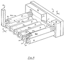
- FIGs. 1 and 2 illustrate a dynamic flood conveyor constructed in accordance with the principles of the invention and including upstanding side walls 11 and 12 and parallel support rollers 13 - 18 each having first 19 and second 60 ends rotatably mounted in one of side walls 11 and 12. Rollers 13 and 18 are the end rollers. The diameter of each roller 13-18 presently preferably equals that of the other rollers 13-18. Each roller 13-18 has a cylindrical outer surface 13A-18A. Rollers 13-18 support and transport a strip of material 25 through the dynamic flood conveyor in the direction of arrow A.
- Rollers 13-18 each turn in the direction indicated by arrows B.
- the ends 19 of each adjacent pair of support rollers 13-18 are presently equally spaced apart.
- Each end 19 is rotatably positioned in one of a series of parallel, vertical, spaced apart retainer slots 26 formed in wall 12.
- the width of a slot 26 is uniform along its length and is slightly greater than the outer diameter of a bushing 40 on an end 18.
- each end 60 is rotatably positioned in one of a series of parallel, vertical, spaced apart retainer slots 27 formed in wall 11.
- the width of slot 27 is uniform along its length and is slightly greater than the outer diameter of a bushing 40 on an end 60.
- End 60 of each roller 13-18 carries a chain sprocket 28 fixedly attached thereto.
- a moving chain 29 engages and rotates each sprocket 28 and roller 13-18.
- Wall 11 includes side dam member 30 extending therealong. End 60 of each support roller 13-18 rotatably extends through an aperture 31 formed through side dam 30. Cylindrical low friction plastic washers 32 seal the space between each roller 13-18 and walls 11 and 12.
- Elongate cylindrical lower fluid containment rollers 20-24 are interposed between and continuously contact and rotate on top of and intermediate the outer cylindrical surfaces 13A-18A of each adjacent pair of support rollers 13-18.
- lower fluid containment roller 20 is interposed between surfaces 13A and 14A of roller pair 13, 14.
- Fluid containment rollers 20-24 are rotated in the direction of arrows C by support rollers 13-18.
- Each fluid containment roller 20-24 is presently of a diameter slightly less than that which would cause the roller to protrude above a generally horizontal imaginary plane passing through substrate strip 25, and has a length less than the distance D between side wall 12 and side dam member 30.
- Each roller 20-24 substantially seals the cylindrical outer surfaces of an adjacent support roller 12-18 pair while generally not impeding the free rotation of the roller pair.
- Upper fluid containment rollers 35A and 36A are parallel to one another and are positioned above end rollers 13 and 18.
- the ends of shafts 37 of rollers 35A and 36A are each rotatably mounted in one of side walls 11 and 12.
- Cylindrical low friction plastic washers 53 and 54 seal the spaces between each roller 35, 36 and walls 11 and 12.
- One end of shaft 37 of roller 35A extends into a vertical slot 26 receiving end 19 of roller 13.
- the other end of shaft 37 of roller 35A extends into a vertical slot 27 receiving end 20 of roller 13.
- the diameter of each end of a shaft 37 is presently generally equivalent to the diameter of ends 19 and 60 of rollers 13-18.
- One end of shaft 37 of roller 35A rotatably passes through an aperture formed through side dam member 30 in the same manner as one end of shaft 37 on roller 36A does through aperture 39 in Fig. 2.
- the portions of each end 19, 20, and the ends of shafts 37 in a slot 26, 27 includes a bushing 40 secured thereto.
- One end of shaft 37 of roller 36A extends into vertical slot 26 which receives end 19 of roller 18.
- the other end of shaft 37 of roller 36A also extends into vertical slot 27 which receives end 60 of roller 18.
- End 38 of roller 36A rotatably extends through an aperture 39 formed in side dam 30.
- Rollers 35A and 36A contact rollers 13 and 18 or contact strip 25 passing over rollers 13 and 18.
- Motive power is transmitted from rollers 13 and 18 to rollers 35A, 36A and causes rollers 35A and 36A to turn in the direction indicated by arrow E.
- Disks 41 are fixedly attached to shaft 42.
- the ends of shaft 42 rotatably extend into vertical slots 26 and 27 which rotatably receive ends 19 and 60 of roller 16.
- the end of rod 42 extending into a slot 27 also rotatably passes through an aperture formed through side dam member 30 in the same manner aperture 39 is formed through member 30 for end of roller 36A.
- Disks 41 on shaft 42 contact the outer surface 16A of roller 16 or contact strip 25 traveling over roller 16.
- Motive power is transmitted from roller 16 to friction wheel 54 at the end of shaft 42 carrying disks 41 and causes disks 41 and shaft 42 to turn in the direction indicated by arrow E.
- Disks 41 prevent a strip of material 25 passing through the apparatus of Figs.
- rollers 13-18 From floating upwardly away from the uppermost portions of support rollers 13-18.
- the uppermost portions of rollers 13-18 lie in and define a horizontally oriented imaginary plane.
- strip of material 25 lies in this imaginary plane.
- the imaginary plane is, in Fig. 1, perpendicular to the plane of the paper of the drawings. Since lower fluid containment rollers 20-24 rotate in a direction which would cause rollers 20-24 to oppose the movement of strip 25 in the direction of arrow A, the diameter of rollers 20-24 is preferably small enough so that rollers 20-24 are each positioned beneath the imaginary plane intersecting the uppermost portions of rollers 13-18.
- Fluid in reservoir 43 generally is above support rollers 13-18 and lower fluid containment rollers 20-24, is between upper fluid containment rollers 35 and 36, and extends above the imaginary plane extending through the uppermost portions of rollers 13-18.
- fluid from reservoir 43 seeps between lower fluid containment rollers 2-24 and support rollers 13-18, and between upper fluid containment rollers 35A and 36A and rollers 13 and 18.
- Additional fluid 445 is introduced into reservoir 43 through at least one conduit member 44 having at least one nozzle mouth 46. positioned beneath the surface of reservoir 43. Fluid flows from nozzle mouth 46 in the directions of travel indicated by arrows F and G.
- the directions of flow F and G of fluid 45 into reservoir 43 are generally parallel to the imaginary plane intersecting the uppermost portions of rollers 13-18, are generally parallel to the planer surface of strip 25, and are generally parallel to the direction of travel A of strip 25 through the apparatus.
- Nozzle mouth 46 is presently preferably positioned above the pass line, i.e., above the upper surface of strip 25.
- the uniform laminar flow of fluid over the upper surface of strip 25 minimizes the formation of eddy currents in fluid reservoir 43 and therefore facilitates the transport of very thin substrate strips 25, and tends to eliminate "dead" areas of chemical interaction between fluid in reservoir 43 and strip 25.
- the flow rate of fluid 45 through conduit 44 into reservoir 43 is adjusted to compensate for and generally equal fluid losses from reservoir 43 during operation of the apparatus.
- a nozzle mouth 46 can also, if desired, be positioned above the surface of reservoir 43. Mouth 46 can, regardless of the position of mouth 46 above or beneath the surface of reservoir 43, be shaped and dimensioned such that fluid flowing through mouth 46 travels radially outwardly away from nozzle 44 in any selected directions(s) of travel. Further, while the direction of travel of fluid emitted from mouth 46 and flowing away from nozzle 44 is presently preferably parallel to the imaginary plane lying in material 25 passing beneath nozzle 44, mouth 46 can also be shaped and dimensioned such that fluid emitted by mouth 46 flows upwardly away from and/or downwardly toward material 25.
- the apparatus of the invention permits the use of solutions in reservoir 43 which contain a high quantity of surfactants. Solutions with a high quantity of surfactants are generally not suitable for use in spray treatment apparatus.
- rollers 35A and 36A and the ends of shaft 42 "float" in their respective slots 26 and 27 and can be readily slidably displaced upwardly away from and then downwardly toward their respective support rollers in the directions indicated by arrows H. This permits rollers 35A and 36A and disks 44 to be upwardly displaced away from their respective operatively associated support rollers when a strip of material 25 is fed through the apparatus.
- Rollers 35A and 36A are each segmented into a plurality of cylindrically shaped segments 80.
- Each segment 80 has a shape and dimension equal to the other remaining segments 80.
- Each segment 80 includes a pair of planar, spaced apart, parallel side faces 78 and 79. Faces 78 and 79 each have a circular peripheral edge and are of equal shape and dimension.
- Cylindrical aperture 81 extends through each segment 80 and interconnects faces 78 and 79.
- Each segment 80 touches at least one immediately adjoining segment 80.
- the face 78 of one segment slidably contacts the face 79 of an immediately adjoining segment.
- segments 80 are drawn in their normal adjoining relationship.
- segments 80 are drawn with a small space in between each adjoining pair of segments 80. These small spaces do not exist during use of the apparatus of the invention, and are incorporated in Fig. 3 to emphasize that each segment 80 preferably is not connected to adjoining segments 80.
- segments 80 and 81 are, for the sake of clarity, shown centered around and on shafts 37. Apertures 81 are spaced away from shafts 37. Under actual operating conditions, the weight of segments 80, the weight of shafts 37, the force W1 and W2 of the fluid in the reservoir bearing outwardly against rollers 35A and 36A, and the rotational forces acting on segments 80 cause the rollers 35A and 36A to move outwardly away from one another and downwardly against a roller 13 or 18 such that apertures 81 contact shaft 37.
- the fluid flow 45 into the flood is sufficient to compensate for fluid losses which occur through small apertures 100 and 101 (Fig. 5) between a workpiece 82 and adjacent segments 80 which are still in contact with roller 16.
- the fluid flow 45 is also sufficient to maintain fluid flowing out of the flood over weir 86 into sump 90.
- Valve 85 controls the rate at which fluid from sump 90 flows under gravity to sump 87.
- Pump 88 returns 45 fluid from sump 87 to the flood intermediate rollers 35A and 36A. Any foam which formed when fluid flowing over weir 86 flowed into sump 90 tends to remain on the surface of the fluid 83 in sump 90 when fluid 83 flows downwardly into sump 87.
- any foam in sump 87 tends to remain on the surface of fluid 84. Consequently, the weir fluid overflow system of the invention minimizes the amount of foam in liquid being returned 45 to the flood. Since the flow of fluid, indicated by arrow V in Fig. 4, is transverse the direction of the flow of fluid indicated by arrows F and G in Fig. 1, the surface fluid flow over weir 86 in the direction of arrow V tends to offset the flow of fluid in the direction of arrows F and G and stabilize the surface of the liquid in the flood.
- each segment 80 is 203,3 cm (0.75 inch) or less, and for pieces of substrate greater than 0,3175 cm (one eighth of an inch) thick is preferably 0,635 cm (0.25 inch) or less.
- shafts 37 are free floating and can be vertically displaced in vertical slots 26 and 27.
- a shaft 37 also bears down against apertures 81 of segments 80 and, along with the weight of segments 80, maintains segments against rollers 13 and 18, respectively. If a shaft 37 was not free floating, but was instead held in a fixed position, such fixed position could position the shaft 37 in the upper part of apertures 81 of a roller 35A, 36A when segments 80 were resting on a roller 13 or 18. This would permit segments 80 to be upwardly displaced until the lower parts of apertures contacted the bottom of a shaft 37.
Landscapes
- Engineering & Computer Science (AREA)
- Chemical & Material Sciences (AREA)
- Manufacturing & Machinery (AREA)
- Microelectronics & Electronic Packaging (AREA)
- Chemical Kinetics & Catalysis (AREA)
- General Chemical & Material Sciences (AREA)
- Materials Engineering (AREA)
- Mechanical Engineering (AREA)
- Metallurgy (AREA)
- Organic Chemistry (AREA)
- Rollers For Roller Conveyors For Transfer (AREA)
Claims (1)
- Dynamischer Fluidförderer zur Verarbeitung der oberen Fläche eines SchaltplatinensubstratS durch Bewegen des Substrats durch einen Fluidkörper, wobei das Substrat eine obere Oberfläche aufweist, und wobei der Förderer umfaßt:(a) ein paar nach oben stehender voneinander beabstandeter Seitenwände (11, 12);(b) im wesentlichen horizontal angeordnete, aneinander angrenzende parallele Tragrollen zum Tragen und Transportieren des Schaltplatinensubstrats, wobei die Tragrollen(i) wenigstens erste (18) und zweite (13) Endrollen umfassen,(ii) die jeweils den Raum zwischen den Seitenwänden überspannen,(iii) die jeweils erste und zweite Enden aufweisen, die jeweils drehbar in einer der Wände (11, 12) befestigt sind, und(iv) die jeweils eine zylindrische Außenfläche (18A, 13A) aufweisen, die den Raum zwischen den Seitenwänden überspannt,wobei jeder der obersten Abschnitte der zylindrischen Außenflächen der Rollen jeweils im wesentlichen in einer im wesentlichen horizontalen imaginären Ebene liegt und diese definiert;(c) Mittel zum Drehen jeder der Tragrollen (18, 13) in einer gemeinsamen Richtung;(d) obere Fluidaufnahmerollmittel (35A), die sich über die horizontale Ebene erstrecken und den Raum zwischen den Seitenwänden überspannen;(e) eine obere Fluidaufnahmerolle (36A), die von den oberen Fluidaufnahmerollmitteln (35A), die den Raum zwischen den Seitenwänden überspannen, beabstandet ist und die über und im wesentlichen parallel zu der ersten Endrolle angeordnet ist und(i) einen horizontal angeordneten Schaft (37), und(ii) ein Paar von Enden, die jeweils drehbar in einer der Seitenwände (11, 12) befestigt sind aufweist;(f) ein Fluidreservoir (43) in dem Fluidförderer, wobei das Fluidreservoir mit der Fluidaufnahmerolle (36A) und oberen Fluidaufnahmerollmitteln (35A) in Verbindung steht und sich im wesentlichen(i) über den Tragrollen,(ii) zwischen und unter Verbindung mit der Fluidaufnahmerolle (36A) und den oberen Fluidaufnahmerollmitteln (35A) und(iii) über der imaginären Ebene erstreckt; und(g) Mittel zum Einspritzen von Fluid in das Reservoir, wobei die Fluidaufnahmerolle (36A) und die oberen Fluidaufnahmerollmittel (35A) als Dämme wirken, um Fluid in dem Reservoir (43) zurückzuhalten;dadurch gekennzeichnet, daß die obere Fluidaufnahmerolle (36A) eine Vielzahl zylindrischer Segmente (80) umfaßt, die einander gleitend berühren und drehbar an dem Schaft (37) befestigt sind, wobei jedes der Segmente eine durchgängig ausgebildete Öffnung (81) aufweist, die so geformt und dimensioniert ist, daß sie den Segmenten erlaubt, relativ zu dem Schaft und der ersten Endrolle vertikal verschoben zu werden, wobei sich die Segmente von einer der Seitenwände zu der anderen der Seitenwände erstrecken und im wesentlichen parallel zu der ersten Endrolle (18) angeordnet sind und kontinuierlich wenigstens eines eines zweiten Kontaktpaares berühren, wobei das zweite Kontaktpaar(i) die zylindrische Außenfläche (18A) der ersten Endrolle (18) und(ii) die obere Oberfläche des Schaltplatinensubstrats (82), das zwischen der Fluidaufnahmerolle (36A) und der ersten Endrolle (18A) hindurchgeht,umfaßt, wobei ausgewählte einzelne der Segmente (80) in Kontakt mit der Endrolle verbleiben, wobei gleichzeitig beim Berühren der oberen Oberfläche des zwischen der Fluidaufnahmerolle (36A) und der ersten Endrolle (18) hindurchgehenden SchaltplatinensubstratS (82), während dieses sich zu den Fluidaufnahmemitteln (35A) hin bewegt, die verbleibenden anderen der Segmente (80) relativ zu den ausgewählten einzelnen Segmenten nach oben verschoben werden, und wobei die nach oben gerichtete Verschiebung der verbleibenden anderen der Fluidaufnahmerolle relativ zu den ausgewählten einzelnen der Segmente (80) der Fluidaufnahmerolle (36A) das das von dem Reservoir über die erste Endrolle (18) entweichende Fluid minimieren, wenn das Schaltplatinensubstrat (82) zwischen der Fluidaufnahmerolle (36A) und der ersten Endrolle (18) in das Reservoir (43) eintritt.
Applications Claiming Priority (2)
| Application Number | Priority Date | Filing Date | Title |
|---|---|---|---|
| US07/485,167 US5007445A (en) | 1990-02-26 | 1990-02-26 | Dynamic flood conveyor with weir |
| US485167 | 1990-02-26 |
Publications (3)
| Publication Number | Publication Date |
|---|---|
| EP0444359A2 EP0444359A2 (de) | 1991-09-04 |
| EP0444359A3 EP0444359A3 (en) | 1993-03-24 |
| EP0444359B1 true EP0444359B1 (de) | 1995-03-01 |
Family
ID=23927145
Family Applications (1)
| Application Number | Title | Priority Date | Filing Date |
|---|---|---|---|
| EP90314259A Expired - Lifetime EP0444359B1 (de) | 1990-02-26 | 1990-12-24 | Dynamischer Fluidumförderer mit Wehr |
Country Status (3)
| Country | Link |
|---|---|
| US (1) | US5007445A (de) |
| EP (1) | EP0444359B1 (de) |
| DE (1) | DE69017423T2 (de) |
Families Citing this family (16)
| Publication number | Priority date | Publication date | Assignee | Title |
|---|---|---|---|---|
| DE4121079A1 (de) * | 1991-06-26 | 1993-01-07 | Schmid Gmbh & Co Geb | Vorrichtung zum behandeln von plattenfoermigen gegenstaenden |
| US5294259A (en) * | 1992-05-18 | 1994-03-15 | International Business Machines Corporation | Fluid treatment device |
| US5378307A (en) * | 1993-04-28 | 1995-01-03 | International Business Machines Corporation | Fluid treatment apparatus |
| US5592958A (en) * | 1995-02-01 | 1997-01-14 | Coates, Asi, Inc. | Flood conveyer |
| US5837067A (en) * | 1995-06-07 | 1998-11-17 | International Business Machines Corporation | Precision fluid head transport |
| US5795625A (en) * | 1996-07-16 | 1998-08-18 | Eastman Kodak Company | Coating solution distribution apparatus |
| DE05075545T1 (de) * | 1998-05-20 | 2006-08-31 | Process Automation International Ltd., Tai Po | Vorrichtung zur Elektroplattierung |
| DE19934300C2 (de) * | 1999-07-21 | 2002-02-07 | Steag Micro Tech Gmbh | Vorrichtung zum Behandeln von Substraten |
| AT408453B (de) * | 1999-09-03 | 2001-12-27 | Andritz Ag Maschf | Verfahren zur nachbehandlung, insbesondere spülung, eines metallbandes |
| DE102008022282A1 (de) * | 2008-04-24 | 2009-10-29 | Gebr. Schmid Gmbh & Co. | Einrichtung und Verfahren zur Behandlung von Silizium-Wafern oder flachen Gegenständen |
| USD601597S1 (en) | 2008-09-03 | 2009-10-06 | P & B Construction, Inc. | Enclosed chamber, adjustable finish-applicator for flat and dimensional surfaces |
| BRPI1011369A2 (pt) | 2009-05-13 | 2016-03-15 | Atotech Deutschland Gmbh | método, estação de tratamento e montagem para tratar um material plano a ser tratado |
| CN103286032B (zh) * | 2013-05-31 | 2016-05-04 | 京东方科技集团股份有限公司 | 涂布设备及彩膜基板制作工艺 |
| CN109436693B (zh) * | 2018-10-10 | 2020-08-28 | 上海航天化工应用研究所 | 危险作业环境下防粉尘传送装置 |
| CN110420795A (zh) * | 2019-08-02 | 2019-11-08 | 马鞍山致青工业设计有限公司 | 一种快干型均匀上漆的板材加工用滚涂机 |
| CN112170118B (zh) * | 2020-09-30 | 2021-10-01 | 杭州汇家厨卫用品有限公司 | 一种用于防静电板材加工的防静电油漆擦涂设备 |
Family Cites Families (5)
| Publication number | Priority date | Publication date | Assignee | Title |
|---|---|---|---|---|
| US1455A (en) * | 1839-12-31 | Lewis r | ||
| DE3001726C2 (de) * | 1980-01-18 | 1984-08-09 | Gebr. Schmid GmbH & Co, 7290 Freudenstadt | Vorrichtung zum Behandeln einer Leiterplatte |
| JPS587830A (ja) * | 1981-07-08 | 1983-01-17 | Hitachi Ltd | 薄片状物品の洗浄方法及び装置 |
| US4591169A (en) * | 1985-06-19 | 1986-05-27 | Rca Corporation | Seal arrangement for retaining a liquid level above a strip passing through a chamber |
| US4724856A (en) * | 1986-03-17 | 1988-02-16 | Pender Don P | Dynamic flood conveyor |
-
1990
- 1990-02-26 US US07/485,167 patent/US5007445A/en not_active Expired - Fee Related
- 1990-12-24 DE DE69017423T patent/DE69017423T2/de not_active Expired - Fee Related
- 1990-12-24 EP EP90314259A patent/EP0444359B1/de not_active Expired - Lifetime
Also Published As
| Publication number | Publication date |
|---|---|
| EP0444359A3 (en) | 1993-03-24 |
| US5007445A (en) | 1991-04-16 |
| DE69017423D1 (de) | 1995-04-06 |
| DE69017423T2 (de) | 1995-09-07 |
| EP0444359A2 (de) | 1991-09-04 |
Similar Documents
| Publication | Publication Date | Title |
|---|---|---|
| US5007445A (en) | Dynamic flood conveyor with weir | |
| US4724856A (en) | Dynamic flood conveyor | |
| KR101341146B1 (ko) | 처리될 평면 재료를 처리하는 방법, 처리 스테이션 및 어셈블리 | |
| US3752054A (en) | Automatic processor for emulsion coated metal templates | |
| US3403098A (en) | Oil skimmers | |
| US3023686A (en) | Automatic film processing apparatus | |
| US4023190A (en) | Film processor | |
| CN218757334U (zh) | 一种水利工程用水闸垃圾拦截装置 | |
| KR930703630A (ko) | 사진 처리장치 | |
| US3692465A (en) | Three roll processing apparatus,and method for utilization thereof | |
| EP0495288B1 (de) | Aus Rollen bestehender Entwicklungstank | |
| US5634481A (en) | Strip treatment installation | |
| JP3735746B2 (ja) | 浮遊物掻寄装置 | |
| CN1098375C (zh) | 处理板形工件,特别是线路板的设备 | |
| US2919705A (en) | Apparatus for treating articles | |
| WO1998044389A1 (en) | An apparatus and a method for processing photographic material | |
| JP2607864Y2 (ja) | 汚泥・浮遊物掻寄装置 | |
| US5426480A (en) | Photographic film processing apparatus | |
| CN222677271U (zh) | 一种沉淀池浮渣刮除机构 | |
| JP2514249Y2 (ja) | 自動現像機内の渡りロ―ラ洗浄装置 | |
| JPS5653792A (en) | Guide for aeration tank | |
| US20110097074A1 (en) | High speed motion picture film processor | |
| JP3241154B2 (ja) | Icリードフレームの表面処理装置 | |
| DE2225637C3 (de) | Vorrichtung zur NaBbehandlung von Blattmaterial | |
| JPH0133646Y2 (de) |
Legal Events
| Date | Code | Title | Description |
|---|---|---|---|
| PUAI | Public reference made under article 153(3) epc to a published international application that has entered the european phase |
Free format text: ORIGINAL CODE: 0009012 |
|
| AK | Designated contracting states |
Kind code of ref document: A2 Designated state(s): DE FR GB IT |
|
| PUAL | Search report despatched |
Free format text: ORIGINAL CODE: 0009013 |
|
| AK | Designated contracting states |
Kind code of ref document: A3 Designated state(s): DE FR GB IT |
|
| 17P | Request for examination filed |
Effective date: 19930916 |
|
| 17Q | First examination report despatched |
Effective date: 19931029 |
|
| GRAA | (expected) grant |
Free format text: ORIGINAL CODE: 0009210 |
|
| AK | Designated contracting states |
Kind code of ref document: B1 Designated state(s): DE FR GB IT |
|
| REF | Corresponds to: |
Ref document number: 69017423 Country of ref document: DE Date of ref document: 19950406 |
|
| ITF | It: translation for a ep patent filed | ||
| ET | Fr: translation filed | ||
| PLBQ | Unpublished change to opponent data |
Free format text: ORIGINAL CODE: EPIDOS OPPO |
|
| PLBI | Opposition filed |
Free format text: ORIGINAL CODE: 0009260 |
|
| PLBF | Reply of patent proprietor to notice(s) of opposition |
Free format text: ORIGINAL CODE: EPIDOS OBSO |
|
| PLBF | Reply of patent proprietor to notice(s) of opposition |
Free format text: ORIGINAL CODE: EPIDOS OBSO |
|
| PLBF | Reply of patent proprietor to notice(s) of opposition |
Free format text: ORIGINAL CODE: EPIDOS OBSO |
|
| 26 | Opposition filed |
Opponent name: GEBR. SCHMID GMBH & CO. Effective date: 19951201 |
|
| PLBF | Reply of patent proprietor to notice(s) of opposition |
Free format text: ORIGINAL CODE: EPIDOS OBSO |
|
| PLBF | Reply of patent proprietor to notice(s) of opposition |
Free format text: ORIGINAL CODE: EPIDOS OBSO |
|
| PLBO | Opposition rejected |
Free format text: ORIGINAL CODE: EPIDOS REJO |
|
| PGFP | Annual fee paid to national office [announced via postgrant information from national office to epo] |
Ref country code: GB Payment date: 19981231 Year of fee payment: 9 Ref country code: FR Payment date: 19981231 Year of fee payment: 9 |
|
| PGFP | Annual fee paid to national office [announced via postgrant information from national office to epo] |
Ref country code: DE Payment date: 19990107 Year of fee payment: 9 |
|
| PLBN | Opposition rejected |
Free format text: ORIGINAL CODE: 0009273 |
|
| STAA | Information on the status of an ep patent application or granted ep patent |
Free format text: STATUS: OPPOSITION REJECTED |
|
| 27O | Opposition rejected |
Effective date: 19981102 |
|
| PG25 | Lapsed in a contracting state [announced via postgrant information from national office to epo] |
Ref country code: GB Free format text: LAPSE BECAUSE OF NON-PAYMENT OF DUE FEES Effective date: 19991224 |
|
| GBPC | Gb: european patent ceased through non-payment of renewal fee |
Effective date: 19991224 |
|
| PG25 | Lapsed in a contracting state [announced via postgrant information from national office to epo] |
Ref country code: FR Free format text: LAPSE BECAUSE OF NON-PAYMENT OF DUE FEES Effective date: 20000831 |
|
| PG25 | Lapsed in a contracting state [announced via postgrant information from national office to epo] |
Ref country code: DE Free format text: LAPSE BECAUSE OF NON-PAYMENT OF DUE FEES Effective date: 20001003 |
|
| REG | Reference to a national code |
Ref country code: FR Ref legal event code: ST |
|
| PG25 | Lapsed in a contracting state [announced via postgrant information from national office to epo] |
Ref country code: IT Free format text: LAPSE BECAUSE OF NON-PAYMENT OF DUE FEES;WARNING: LAPSES OF ITALIAN PATENTS WITH EFFECTIVE DATE BEFORE 2007 MAY HAVE OCCURRED AT ANY TIME BEFORE 2007. THE CORRECT EFFECTIVE DATE MAY BE DIFFERENT FROM THE ONE RECORDED. Effective date: 20051224 |