EP0444391A2 - Procédé et dispositif pour le remplissage d'espace intérieur de verre isolant en forme de départ de gaz - Google Patents
Procédé et dispositif pour le remplissage d'espace intérieur de verre isolant en forme de départ de gaz Download PDFInfo
- Publication number
- EP0444391A2 EP0444391A2 EP90890281A EP90890281A EP0444391A2 EP 0444391 A2 EP0444391 A2 EP 0444391A2 EP 90890281 A EP90890281 A EP 90890281A EP 90890281 A EP90890281 A EP 90890281A EP 0444391 A2 EP0444391 A2 EP 0444391A2
- Authority
- EP
- European Patent Office
- Prior art keywords
- insulating glass
- glass blank
- air
- gas
- interior
- Prior art date
- Legal status (The legal status is an assumption and is not a legal conclusion. Google has not performed a legal analysis and makes no representation as to the accuracy of the status listed.)
- Granted
Links
- 239000011521 glass Substances 0.000 title claims abstract description 105
- 238000000034 method Methods 0.000 title claims description 43
- 239000007789 gas Substances 0.000 claims abstract description 78
- 239000000523 sample Substances 0.000 claims abstract description 48
- 125000006850 spacer group Chemical group 0.000 claims abstract description 32
- XKRFYHLGVUSROY-UHFFFAOYSA-N Argon Chemical compound [Ar] XKRFYHLGVUSROY-UHFFFAOYSA-N 0.000 claims abstract description 27
- 239000000203 mixture Substances 0.000 claims abstract description 22
- 229910052786 argon Inorganic materials 0.000 claims abstract description 14
- 238000003825 pressing Methods 0.000 claims abstract description 12
- 238000007664 blowing Methods 0.000 claims description 3
- 238000005452 bending Methods 0.000 claims 1
- 238000004519 manufacturing process Methods 0.000 description 3
- 229910018503 SF6 Inorganic materials 0.000 description 2
- 238000010276 construction Methods 0.000 description 2
- 238000007789 sealing Methods 0.000 description 2
- SFZCNBIFKDRMGX-UHFFFAOYSA-N sulfur hexafluoride Chemical compound FS(F)(F)(F)(F)F SFZCNBIFKDRMGX-UHFFFAOYSA-N 0.000 description 2
- 229960000909 sulfur hexafluoride Drugs 0.000 description 2
- QVGXLLKOCUKJST-UHFFFAOYSA-N atomic oxygen Chemical compound [O] QVGXLLKOCUKJST-UHFFFAOYSA-N 0.000 description 1
- 230000015572 biosynthetic process Effects 0.000 description 1
- 230000001419 dependent effect Effects 0.000 description 1
- 238000005553 drilling Methods 0.000 description 1
- 239000006260 foam Substances 0.000 description 1
- 239000001301 oxygen Substances 0.000 description 1
- 229910052760 oxygen Inorganic materials 0.000 description 1
Images

Classifications
-
- E—FIXED CONSTRUCTIONS
- E06—DOORS, WINDOWS, SHUTTERS, OR ROLLER BLINDS IN GENERAL; LADDERS
- E06B—FIXED OR MOVABLE CLOSURES FOR OPENINGS IN BUILDINGS, VEHICLES, FENCES OR LIKE ENCLOSURES IN GENERAL, e.g. DOORS, WINDOWS, BLINDS, GATES
- E06B3/00—Window sashes, door leaves, or like elements for closing wall or like openings; Layout of fixed or moving closures, e.g. windows in wall or like openings; Features of rigidly-mounted outer frames relating to the mounting of wing frames
- E06B3/66—Units comprising two or more parallel glass or like panes permanently secured together
- E06B3/677—Evacuating or filling the gap between the panes ; Equilibration of inside and outside pressure; Preventing condensation in the gap between the panes; Cleaning the gap between the panes
- E06B3/6775—Evacuating or filling the gap during assembly
Definitions
- the invention relates to a method for filling the interior of insulating glass blanks with a gas other than air, in particular with argon, with a probe for supplying the gas and a probe for extracting air or air-gas mixture from the inside of the insulating glass blank Interior of the insulating glass blank are introduced.
- a gas other than air in particular with argon
- Such filling gases are, for example: argon or a so-called heavy gas, such as sulfur hexafluoride.
- a method of operation in which the gas exchange is to take place through a gap in the region of the lower horizontal leg of a spacer frame is known from DE-OS 34 02 323.
- the invention has for its object to improve the method of the type mentioned in such a way that not only the actual gas exchange takes place easily and quickly, but also that the production and subsequent closing of holes in the spacer frame is avoided without the disadvantages of the above described methods in which the gas exchange takes place via a gap in the region of the lower horizontal leg of the spacer frame.
- this object is achieved in that the insulating glass pane blank is pressed in a press after assembling the pane package, that a pane of the insulating glass pane blank is held at a distance from the spacer frame in the area of a corner, and that both probes are introduced into the interior of the insulating glass pane blank in the area of this corner.
- the preferred procedure is to compress the pane package essentially vertically and one pane in the area of one of the lower corners at a distance from Spacer frame holds - is kept open, the probes for gas exchange can be introduced without the disadvantages of the known procedures described above, even without the production of holes in the spacer frame.
- the gas exchange takes place particularly quickly and easily if the procedure is such that a gas stream which is aligned essentially parallel to the lower, horizontal leg of the spacer frame is blown into the interior of the insulating glass blank from the probe for supplying gas.
- this method of operation mixing of the supplied gas with the outflowing air or air-gas mixture is largely prevented, since the gas which is intended to replace the air in the interior of the pane widens from the side opposite the filling point to the filling side moving progressively and gradually pushing the air-gas mixture or the air towards the suction probe, compressing it.
- the procedure is such that air or air-gas mixture is introduced into the interior of the insulating glass blank withdrawn inserted probe to an extent that there is a pressure in the interior of the insulating glass blank during the gas exchange, which is higher than the pressure in the environment.
- This procedure has the advantage that special sealing measures are unnecessary and yet no air is sucked into the interior of the insulating glass blank, the resulting losses being negligible, especially if the interior of the insulating glass blank is filled with argon or a similarly cheap gas.
- the process according to the invention can be carried out in such a way that the insulating glass blank is also pressed in the area of the open corner.
- the gas introduced by one probe for example argon
- the probes are not introduced through holes, but through the open area in the corner into the interior of the insulating glass blank, they can also be used in the method according to the invention if the probes are in different directions, e.g. point away from each other, are simultaneously introduced into the interior of the insulating glass pane.
- the amount of gas used in the process according to the invention can be determined simply by continuing the gas exchange until the proportion of the air-gas mixture extracted via the one probe Air falls below a predetermined value.
- the volume of the interior of the insulating glass blank can be calculated and a quantity of gas can be introduced into the interior of the insulating glass pane that corresponds to the calculated volume by a predetermined fraction of this volume.
- the invention further relates to a device which is particularly suitable for carrying out the method according to the invention.
- the device for carrying out the method is characterized by two pressure plates which can be approximated to one another for pressing the insulating glass blank, with a probe for introducing gas into the space between the glass panes of the insulating glass blank and with a probe for extracting air or air.
- the press for example, one of the types known from DE-PS 31 30 645
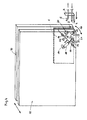
- the disk package is pressed and the cover disk is held in a lower corner 2 of the disk package, preferably the front, lower corner, at a distance from the spacer frame and / or from the spacer frame lifted off or held at a distance from the spacer frame.
- two probes 4 and 5 which are mounted close to one another on an angled support 3 and via which the gas exchange takes place, are introduced into the interior of the insulating glass blank.
- the probe 4 supplying the special gas e.g. argon
- the probe 4 supplying the special gas is aligned horizontally and blows the gas flow into the space between the glass panes at high speed parallel to the lower, horizontal leg of the spacer frame.
- the second probe 5 which is mounted on the angled support 3 and which is applied from the outside to the corner 2 of the insulating glass blank 1, optionally with the interposition of a seal (elastic foam), has an opening which is directed obliquely upwards and is used for suction of air or air-gas mixture displaced from the interior of the insulating glass blank.
- a seal elastic foam
- the gas exchange is carried out in such a way that there is always at least a small one in the interior of the insulating glass blank Overpressure prevails, so that gas can be exchanged continuously and at most excess air or gas-air mixture is displaced from the interior, which is not a problem since the filling gas, especially if it is argon, is not expensive.
- the gas flow follows the inner circumference of the spacer frame and compresses towards the center, so that air is gradually compressed in an increasingly smaller area and displaced from the interior of the insulating glass blank , as indicated in FIGS. 1 to 3 by the "front" 6 between the filling gas and the air.
- the gas filling is controlled either by measuring the residual oxygen content in the gas-air mixture drawn from the interior of the insulating glass blank, by determining the composition of the air-gas mixture in the interior of the insulating glass blank and / or by determining (calculating) the volume of the interior of the pane and Supply of a correspondingly metered amount of gas, a certain loss due to the prevailing overpressure being taken into account by the fact that the calculated volume amount by an example empirically determined fraction is increased.
- Advantages of the method according to the invention are that it is possible to work continuously and does not have to be constantly switched between blowing and suctioning.
- the drilling and subsequent closing of openings in the spacer frame through which the probes are to be inserted are omitted in the working method according to the invention.
- Another advantage is that the mixing between supplied gas and air in the interior of the insulating glass blank is kept within limits, since such mixing is limited Extent occurs.
- a press schematically indicated in Fig. 4 has two press plates 10 and 11 which are movable relative to each other, as is known per se for presses for pressing insulating glass blanks.
- the construction of the press with the plates 10 and 11 and the drive for moving the movable press plate, e.g. the plate 11 can have a construction as is known per se. Examples of known pressing devices which can be used in the present context are described in AT-PS 385 499 or in Austrian patent application A 2956/87, which was published on June 15, 1990.
- only a lower corner region 12 of the press plate 11 can be pivoted with respect to the press plate 11 and is connected to the latter via hinges 13 and 14.
- a pressure medium cylinder 15 is provided, which is connected on the one hand at 16 to the press plate 11 and on the other hand via an extension 17 projecting from the corner region 12.
- the corner region 12 can be pivoted back and forth in the direction of the double arrow 18 (FIG. 4).
- two suction heads 19 and 20 are provided in the corner region 12 of the pressure plate 11 in the exemplary embodiment shown, and can be subjected to negative pressure via lines 21, 22.
- the suction heads 19 and 20 lie against the one glass pane of the insulating glass blank 1, so that in its corner 2 by actuating the pressure cylinder 15 and pivoting the corner region 12 of the press plate 11, the one glass pane from the spacer frame 1 located between the two glass panes of the insulating glass blank 1 is lifted off.
- the probe 4 and the probe 5 are inserted into the opening thus formed, whereby the angular support 3 bears on the insulating glass blank 1 in the area of the corner 1 'thereof, as mentioned above, on the outer circumference of the insulating glass blank 1.
- the carrier 3 with the probes 4 and 5 is removed again, for which purpose an actuating device (not shown) for the holder 3 is provided, and the pressure medium cylinder 15 is actuated so that the corner region 12 of the plate 11 swings back again and thus the insulating glass blank is pressed in the area of the initially still open corner 2.
- the press is opened by moving the pressing plate 11 away from the pressing plate 10 and conveying the insulating glass blank 1 filled with gas, for example argon, from the press and, for example, to a sealing station.
- gas for example argon
Landscapes
- Engineering & Computer Science (AREA)
- Civil Engineering (AREA)
- Structural Engineering (AREA)
- Joining Of Glass To Other Materials (AREA)
- Securing Of Glass Panes Or The Like (AREA)
- Filling Or Discharging Of Gas Storage Vessels (AREA)
- Glass Compositions (AREA)
- Automobile Manufacture Line, Endless Track Vehicle, Trailer (AREA)
Applications Claiming Priority (3)
| Application Number | Priority Date | Filing Date | Title |
|---|---|---|---|
| AT473/90 | 1990-02-28 | ||
| AT47390 | 1990-02-28 | ||
| AT0047390A AT408982B (de) | 1990-02-28 | 1990-02-28 | Verfahren zum füllen des innenraumes von isolierglasscheiben mit gas |
Publications (4)
| Publication Number | Publication Date |
|---|---|
| EP0444391A2 true EP0444391A2 (fr) | 1991-09-04 |
| EP0444391A3 EP0444391A3 (en) | 1992-04-08 |
| EP0444391B1 EP0444391B1 (fr) | 1994-09-21 |
| EP0444391B2 EP0444391B2 (fr) | 2000-12-27 |
Family
ID=3491550
Family Applications (1)
| Application Number | Title | Priority Date | Filing Date |
|---|---|---|---|
| EP90890281A Expired - Lifetime EP0444391B2 (fr) | 1990-02-28 | 1990-10-15 | Procédé pour le remplissage d'espace intérieur de verre isolant en forme de départ de gaz |
Country Status (5)
| Country | Link |
|---|---|
| US (1) | US5110337A (fr) |
| EP (1) | EP0444391B2 (fr) |
| AT (2) | AT408982B (fr) |
| DE (2) | DE9014304U1 (fr) |
| ES (1) | ES2062498T5 (fr) |
Cited By (4)
| Publication number | Priority date | Publication date | Assignee | Title |
|---|---|---|---|---|
| US5413156A (en) * | 1992-12-18 | 1995-05-09 | Lisec; Peter | Process and apparatus for filling insulating glass panes with a gas other than air |
| EP0715053A2 (fr) | 1994-10-28 | 1996-06-05 | VIANELLO Fortunato - DAVANZO Nadia trading under the trading style FOR.EL. BASE DI VIANELLO & C. S.n.c. | Dispositif et procédé pour remplir automatiquement des vitrages isolants |
| US5626712A (en) * | 1994-03-24 | 1997-05-06 | Lisec; Peter | Device for filling insulating glass panes with heavy gas |
| EP0805254A3 (fr) * | 1996-04-29 | 1999-09-22 | Lenhardt Maschinenbau GmbH | Procédé pour la fabrication de vitres isolantes à écarteur thermoplastique |
Families Citing this family (23)
| Publication number | Priority date | Publication date | Assignee | Title |
|---|---|---|---|---|
| DE58900360D1 (de) * | 1988-05-04 | 1991-11-14 | Lenhardt Maschinenbau | Verfahren und vorrichtung zum fuellen von isolierglasscheiben mit einem schwergas. |
| EP0498787A3 (en) * | 1991-02-04 | 1992-10-14 | Peter Lisec | Method and device for manufacturing insulating glazing units |
| US5246042A (en) * | 1991-09-24 | 1993-09-21 | Litton Systems Canada Limited | Method of filling a suspended particle display |
| DE4212256C2 (de) * | 1992-04-11 | 1998-06-04 | Lenhardt Maschinenbau | Vorrichtung zum Zusammenbauen von zwei Isolierglasscheiben die mit einem von Luft verschiedenen Gas gefüllt sind |
| DE4231424C2 (de) * | 1992-09-19 | 1998-04-09 | Lenhardt Maschinenbau | Verfahren und Vorrichtung zum Zusammenbauen von Isolierglasscheiben, deren Glastafeln durch einen plastischen Abstandhalter auf Abstand gehalten und miteinander verklebt sind |
| DE4335673C1 (de) * | 1993-10-20 | 1995-05-11 | Lenhardt Maschinenbau | Verfahren und Vorrichtung zum Zusammenbauen von Isolierglasscheiben mit rahmenförmigen Abstandhaltern aus einer plastischen Masse |
| DE4335671A1 (de) * | 1993-10-20 | 1995-05-04 | Lenhardt Maschinenbau | Verfahren und Vorrichtung zum Zusammenbauen von Isolierglasscheiben mit rahmenförmigen Abstandhaltern aus einer plastischen Masse |
| US6068720A (en) * | 1998-07-01 | 2000-05-30 | Edge Seal Technologies, Inc. | Method of manufacturing insulating glass units |
| US20030085238A1 (en) * | 2001-11-06 | 2003-05-08 | Segro Bradley A | Apparatus for dosing liquid gas into a multipane gas unit |
| US6622456B2 (en) | 2001-11-06 | 2003-09-23 | Truseal Telenologies, Inc. | Method and apparatus for filling the inner space of insulating glass units with inert gases |
| WO2009020615A1 (fr) * | 2007-08-07 | 2009-02-12 | Hunter Douglas Inc. | Panneau de verre isolé translucide |
| US8235076B2 (en) * | 2009-02-02 | 2012-08-07 | American Air Liquide, Inc. | Method and system for optimized filling of an enclosure |
| US8627856B2 (en) * | 2010-06-28 | 2014-01-14 | Integrated Automation Systems, Llc | Continuous gas filling process and apparatus for fabrication of insulating glass units |
| GB2483249A (en) * | 2010-09-01 | 2012-03-07 | Inagas | Gas filling apparatus |
| AT510165B1 (de) * | 2010-09-23 | 2012-02-15 | Inova Lisec Technologiezentrum | Verfahren zum herstellen von mit einem von luft verschiedenen gas gefülltem isolierglas |
| US8905085B2 (en) * | 2011-09-09 | 2014-12-09 | Erdman Automation Corporation | Apparatus for edge sealing and simultaneous gas filling of insulated glass units |
| US10113354B2 (en) | 2013-12-31 | 2018-10-30 | Cardinal Ig Company | Multiple-pane insulating glazing unit assembly, gas filling, and pressing machine |
| US9951553B2 (en) | 2014-06-05 | 2018-04-24 | Erdman Automation Corporation | High speed parallel process insulated glass manufacturing line |
| US10968685B2 (en) | 2016-01-04 | 2021-04-06 | PDS IG Holding LLC | Gas filling of an insulating glass unit |
| US10253552B2 (en) | 2016-04-21 | 2019-04-09 | Erdman Automation Corporation | High speed parallel process insulated glass manufacturing line |
| US11187028B2 (en) | 2017-07-01 | 2021-11-30 | PDSD IG Holding LLC | Filling and sealing device and method for an insulated glass unit |
| US12467311B2 (en) | 2022-01-12 | 2025-11-11 | Erdman Automation Corporation | Insulated glass unit manufacturing station and assembly line with controlled heating of spacer |
| US20240109755A1 (en) * | 2022-09-29 | 2024-04-04 | Hyundai Motor Company | Duplex elevator |
Family Cites Families (21)
| Publication number | Priority date | Publication date | Assignee | Title |
|---|---|---|---|---|
| US2756467A (en) * | 1952-11-05 | 1956-07-31 | Etling Birtus Oliver | Multiple-pane glazing unit and manufacture thereof |
| LU58848A1 (fr) * | 1969-06-11 | 1971-03-09 | ||
| US3683974A (en) * | 1970-10-08 | 1972-08-15 | Ppg Industries Inc | Method for purging and filling multiple glazed units |
| US3811484A (en) * | 1971-06-14 | 1974-05-21 | E Engelbrecht | Method and apparatus for delivering a predetermined volume of a liquid |
| US4061163A (en) * | 1976-07-06 | 1977-12-06 | Gte Sylvania Incorporated | Method of filling electrochemical cells with electrolyte |
| DE2644851A1 (de) * | 1976-10-05 | 1978-04-06 | Eberhard Halle | Vorrichtung zur gasabfuellung von schalldaemmscheiben |
| AT370201B (de) * | 1977-05-18 | 1983-03-10 | Lisec Peter Glastech Ind | Vorrichtung zum zusammenstellen von mehrscheiben- isolierglas |
| SU729147A1 (ru) * | 1978-09-05 | 1980-04-25 | За витель | Способ изготовлени стеклопакетов |
| DE3025122C2 (de) * | 1980-07-03 | 1982-04-15 | DCL Glass Consult GmbH, 8000 München | Verfahren und Vorrichtung zum Befüllen einer Isolierglaseinheit mit einem Füllgas |
| AT370706B (de) * | 1981-04-03 | 1983-04-25 | Lisec Peter | Vorrichtung zum zusammenstellen von isolierglasscheiben |
| DE3117255C1 (de) * | 1981-04-30 | 1983-01-27 | DCL Glass Consult GmbH, 8000 München | Sonde zum Einleiten eines Füllgases in eine Isolierglaseinheit |
| DE3117256C2 (de) * | 1981-04-30 | 1983-01-27 | DCL Glass Consult GmbH, 8000 München | Verfahren zum Einleiten eines Füllgases in eine Isolierglaseinheit und Sonde zur Durchführung des Verfahrens |
| AT385499B (de) * | 1981-05-11 | 1988-04-11 | Lisec Peter | Vorrichtung zum pressen von isolierglas |
| AT368985B (de) * | 1981-05-26 | 1982-11-25 | Lisec Peter | Vorrichtung zum fuellen von isolierglas mit schwergas |
| US4450660A (en) * | 1982-09-29 | 1984-05-29 | Dean E Keith | Thermal barrier |
| DE3402323A1 (de) * | 1984-01-24 | 1985-08-01 | Interpane Entwicklungs- und Beratungsgesellschaft mbH & Co. KG, 3471 Lauenförde | Verfahren zum herstellen eines wenigstens aus zwei scheiben bestehenden isolierglases |
| AT393827B (de) * | 1987-01-15 | 1991-12-27 | Lisec Peter | Verfahren und vorrichtung zum fuellen einer isolierglaseinheit mit fuellgas |
| DK164274C (da) * | 1987-10-23 | 1992-10-19 | Neste Oy | Fremgangsmaade til at foere en gas eller vaeske, hvis temperatur er lavere end temperaturen i en underjordisk beholder, frem til den underjordiske beholder samt et foederoersaggregat til beholderen til brug ved udoevelse af fremgangsmaaden. |
| AT393830B (de) * | 1988-01-11 | 1991-12-27 | Lisec Peter | Vorrichtung zum fuellen von isolierglas mit sondergas |
| DE3914706A1 (de) * | 1988-05-04 | 1989-12-14 | Lenhardt Maschinenbau | Verfahren und vorrichtung zum zusammenbauen von isolierglasscheiben, die mit einem von luft verschiedenen gas gefuellt sind |
| DE58900360D1 (de) * | 1988-05-04 | 1991-11-14 | Lenhardt Maschinenbau | Verfahren und vorrichtung zum fuellen von isolierglasscheiben mit einem schwergas. |
-
1990
- 1990-02-28 AT AT0047390A patent/AT408982B/de not_active IP Right Cessation
- 1990-10-15 ES ES90890281T patent/ES2062498T5/es not_active Expired - Lifetime
- 1990-10-15 DE DE9014304U patent/DE9014304U1/de not_active Expired - Lifetime
- 1990-10-15 AT AT90890281T patent/ATE112010T1/de not_active IP Right Cessation
- 1990-10-15 EP EP90890281A patent/EP0444391B2/fr not_active Expired - Lifetime
- 1990-10-15 US US07/597,765 patent/US5110337A/en not_active Expired - Lifetime
- 1990-10-15 DE DE59007269T patent/DE59007269D1/de not_active Expired - Lifetime
Cited By (7)
| Publication number | Priority date | Publication date | Assignee | Title |
|---|---|---|---|---|
| US5413156A (en) * | 1992-12-18 | 1995-05-09 | Lisec; Peter | Process and apparatus for filling insulating glass panes with a gas other than air |
| US5476124A (en) * | 1992-12-18 | 1995-12-19 | Lisec; Peter | Process and apparatus for filling insulating glass panes with a gas other than air |
| DE4327977C2 (de) * | 1992-12-18 | 1998-11-05 | Peter Lisec | Vorrichtung zum Herstellen von mit Füllgas gefüllten Isolierglasscheiben |
| US5626712A (en) * | 1994-03-24 | 1997-05-06 | Lisec; Peter | Device for filling insulating glass panes with heavy gas |
| US5645678A (en) * | 1994-03-24 | 1997-07-08 | Lisec; Peter | Device for producing insulating glass panes filled with heavy gas |
| EP0715053A2 (fr) | 1994-10-28 | 1996-06-05 | VIANELLO Fortunato - DAVANZO Nadia trading under the trading style FOR.EL. BASE DI VIANELLO & C. S.n.c. | Dispositif et procédé pour remplir automatiquement des vitrages isolants |
| EP0805254A3 (fr) * | 1996-04-29 | 1999-09-22 | Lenhardt Maschinenbau GmbH | Procédé pour la fabrication de vitres isolantes à écarteur thermoplastique |
Also Published As
| Publication number | Publication date |
|---|---|
| ATA47390A (de) | 1992-01-15 |
| ES2062498T5 (es) | 2001-03-16 |
| ATE112010T1 (de) | 1994-10-15 |
| AT408982B (de) | 2002-04-25 |
| DE9014304U1 (de) | 1991-01-31 |
| EP0444391B1 (fr) | 1994-09-21 |
| EP0444391B2 (fr) | 2000-12-27 |
| ES2062498T3 (es) | 1994-12-16 |
| DE59007269D1 (de) | 1994-10-27 |
| EP0444391A3 (en) | 1992-04-08 |
| US5110337A (en) | 1992-05-05 |
Similar Documents
| Publication | Publication Date | Title |
|---|---|---|
| EP0444391B1 (fr) | Procédé et dispositif pour le remplissage d'espace intérieur de verre isolant en forme de départ de gaz | |
| AT393827B (de) | Verfahren und vorrichtung zum fuellen einer isolierglaseinheit mit fuellgas | |
| EP0406325B1 (fr) | Procede et dispositif pour remplir des vitres isolantes de gaz lourd | |
| EP2105383B2 (fr) | Machine d'emballage | |
| EP0023264B1 (fr) | Machine d'emballage | |
| EP0453712B1 (fr) | Dispositif pour l'évacuation et la fermeture des sachets d'emballage | |
| DE390689T1 (de) | Rotierende schneidvorrichtung. | |
| DE69505880T3 (de) | Verfahren zum Herstellen von Gussformen | |
| DE4307403A1 (de) | Verfahren und Vorrichtung zum Einrichten, Gasfüllen und Verpressen von Einzelscheiben und/oder bereits vorgefertigten Scheibenanordnungen als zwei Komponenten bei der Herstellung von Isolierglasscheiben | |
| EP0498787A2 (fr) | Procédé et dispositif pour la fabrication de vitrages isolants | |
| DE4100697A1 (de) | Verfahren und vorrichtung zum fuellen des innenraumes von isolierglasscheibenrohlingen mit gas | |
| EP0760892B1 (fr) | Procede et dispositif permettant de remplir l'espace intermediaire compris entre deux vitres d'un panneau de verre isolant | |
| DE2757886A1 (de) | Verfahren und vorrichtung zur herstellung von eckverbindungen von metallrahmen | |
| DE102008015691B3 (de) | Vorrichtung und Verfahren zum Verpacken von Produkten in Beuteln | |
| DE60004077T2 (de) | Automatische verpackungsmaschine zum siegeln von beuteln in kontrollierter atmosphäre | |
| DE60314914T2 (de) | Verfahren und einrichtung zur extraktion elektronischer komponenten aus röhren | |
| DE2122648B2 (de) | Vorrichtung zum evakuieren und verschliessen von fuellgut enthaltenden beuteln aus kunststoff in einer vakuumkammer | |
| AT399145B (de) | Verfahren und vorrichtung zum herstellen von isolierglasscheiben | |
| DE1058924B (de) | Vorrichtung zum Evakuieren und Begasen von Packungen | |
| DE881013C (de) | Vorrichtung zur Herstellung von Schreibminen und aehnlichen Erzeugnissen | |
| DE657061C (de) | Vorrichtung zum Einsetzen des Halses in den Schachtelunterteil | |
| EP0630818B1 (fr) | Procédé et dispositif pour remplir des sacs | |
| AT409128B (de) | Verfahren zum zusammenbauen von isolierglasscheiben, deren innenraum mit einem schwergas gefüllt ist | |
| DE2752184C2 (de) | Verpackungsmaschine | |
| DE9422004U1 (de) | Vorrichtung zum Einrichten, Gasfüllen und Verpressen von Einzelscheiben und/oder bereits vorgefertigten Scheibenanordnungen als zwei Komponenten bei der Herstellung von Isolierglasscheiben |
Legal Events
| Date | Code | Title | Description |
|---|---|---|---|
| PUAI | Public reference made under article 153(3) epc to a published international application that has entered the european phase |
Free format text: ORIGINAL CODE: 0009012 |
|
| AK | Designated contracting states |
Kind code of ref document: A2 Designated state(s): AT BE CH DE DK ES FR GB GR IT LI LU NL SE |
|
| PUAL | Search report despatched |
Free format text: ORIGINAL CODE: 0009013 |
|
| AK | Designated contracting states |
Kind code of ref document: A3 Designated state(s): AT BE CH DE DK ES FR GB GR IT LI LU NL SE |
|
| 17P | Request for examination filed |
Effective date: 19920409 |
|
| 17Q | First examination report despatched |
Effective date: 19930812 |
|
| GRAA | (expected) grant |
Free format text: ORIGINAL CODE: 0009210 |
|
| AK | Designated contracting states |
Kind code of ref document: B1 Designated state(s): AT BE CH DE DK ES FR GB GR IT LI LU NL SE |
|
| PG25 | Lapsed in a contracting state [announced via postgrant information from national office to epo] |
Ref country code: NL Effective date: 19940921 Ref country code: BE Effective date: 19940921 Ref country code: GR Free format text: LAPSE BECAUSE OF FAILURE TO SUBMIT A TRANSLATION OF THE DESCRIPTION OR TO PAY THE FEE WITHIN THE PRESCRIBED TIME-LIMIT Effective date: 19940921 Ref country code: DK Effective date: 19940921 |
|
| REF | Corresponds to: |
Ref document number: 112010 Country of ref document: AT Date of ref document: 19941015 Kind code of ref document: T |
|
| ET | Fr: translation filed | ||
| REF | Corresponds to: |
Ref document number: 59007269 Country of ref document: DE Date of ref document: 19941027 |
|
| PG25 | Lapsed in a contracting state [announced via postgrant information from national office to epo] |
Ref country code: LU Free format text: LAPSE BECAUSE OF NON-PAYMENT OF DUE FEES Effective date: 19941031 |
|
| GBT | Gb: translation of ep patent filed (gb section 77(6)(a)/1977) |
Effective date: 19941003 |
|
| ITF | It: translation for a ep patent filed | ||
| REG | Reference to a national code |
Ref country code: ES Ref legal event code: FG2A Ref document number: 2062498 Country of ref document: ES Kind code of ref document: T3 |
|
| PG25 | Lapsed in a contracting state [announced via postgrant information from national office to epo] |
Ref country code: SE Effective date: 19941221 |
|
| NLV1 | Nl: lapsed or annulled due to failure to fulfill the requirements of art. 29p and 29m of the patents act | ||
| PLBI | Opposition filed |
Free format text: ORIGINAL CODE: 0009260 |
|
| 26 | Opposition filed |
Opponent name: LENHARDT MASCHINENBAU GMBH Effective date: 19950621 |
|
| PLAW | Interlocutory decision in opposition |
Free format text: ORIGINAL CODE: EPIDOS IDOP |
|
| APAC | Appeal dossier modified |
Free format text: ORIGINAL CODE: EPIDOS NOAPO |
|
| APAE | Appeal reference modified |
Free format text: ORIGINAL CODE: EPIDOS REFNO |
|
| APAC | Appeal dossier modified |
Free format text: ORIGINAL CODE: EPIDOS NOAPO |
|
| APAC | Appeal dossier modified |
Free format text: ORIGINAL CODE: EPIDOS NOAPO |
|
| PLAW | Interlocutory decision in opposition |
Free format text: ORIGINAL CODE: EPIDOS IDOP |
|
| RTI2 | Title (correction) |
Free format text: METHOD FOR FILLING THE INNER SPACE OF INSULATING GLASS CLOTS WITH GAS |
|
| PUAH | Patent maintained in amended form |
Free format text: ORIGINAL CODE: 0009272 |
|
| STAA | Information on the status of an ep patent application or granted ep patent |
Free format text: STATUS: PATENT MAINTAINED AS AMENDED |
|
| 27A | Patent maintained in amended form |
Effective date: 20001227 |
|
| AK | Designated contracting states |
Kind code of ref document: B2 Designated state(s): AT BE CH DE DK ES FR GB GR IT LI LU NL SE |
|
| ITF | It: translation for a ep patent filed | ||
| REG | Reference to a national code |
Ref country code: CH Ref legal event code: AEN Free format text: AUFRECHTERHALTUNG DES PATENTES IN GEAENDERTER FORM |
|
| REG | Reference to a national code |
Ref country code: ES Ref legal event code: DC2A Kind code of ref document: T5 Effective date: 20010214 |
|
| GBTA | Gb: translation of amended ep patent filed (gb section 77(6)(b)/1977) | ||
| ET3 | Fr: translation filed ** decision concerning opposition | ||
| REG | Reference to a national code |
Ref country code: GB Ref legal event code: IF02 |
|
| PGFP | Annual fee paid to national office [announced via postgrant information from national office to epo] |
Ref country code: FR Payment date: 20041007 Year of fee payment: 15 |
|
| APAH | Appeal reference modified |
Free format text: ORIGINAL CODE: EPIDOSCREFNO |
|
| PG25 | Lapsed in a contracting state [announced via postgrant information from national office to epo] |
Ref country code: FR Free format text: LAPSE BECAUSE OF NON-PAYMENT OF DUE FEES Effective date: 20060630 |
|
| PGFP | Annual fee paid to national office [announced via postgrant information from national office to epo] |
Ref country code: CH Payment date: 20061012 Year of fee payment: 17 |
|
| PGFP | Annual fee paid to national office [announced via postgrant information from national office to epo] |
Ref country code: AT Payment date: 20061018 Year of fee payment: 17 |
|
| REG | Reference to a national code |
Ref country code: FR Ref legal event code: ST Effective date: 20060630 |
|
| PGFP | Annual fee paid to national office [announced via postgrant information from national office to epo] |
Ref country code: GB Payment date: 20061023 Year of fee payment: 17 |
|
| PGFP | Annual fee paid to national office [announced via postgrant information from national office to epo] |
Ref country code: ES Payment date: 20061030 Year of fee payment: 17 |
|
| PGFP | Annual fee paid to national office [announced via postgrant information from national office to epo] |
Ref country code: IT Payment date: 20071025 Year of fee payment: 18 |
|
| GBPC | Gb: european patent ceased through non-payment of renewal fee |
Effective date: 20071015 |
|
| REG | Reference to a national code |
Ref country code: CH Ref legal event code: PL |
|
| PG25 | Lapsed in a contracting state [announced via postgrant information from national office to epo] |
Ref country code: LI Free format text: LAPSE BECAUSE OF NON-PAYMENT OF DUE FEES Effective date: 20071031 Ref country code: CH Free format text: LAPSE BECAUSE OF NON-PAYMENT OF DUE FEES Effective date: 20071031 |
|
| PG25 | Lapsed in a contracting state [announced via postgrant information from national office to epo] |
Ref country code: AT Free format text: LAPSE BECAUSE OF NON-PAYMENT OF DUE FEES Effective date: 20071015 |
|
| PG25 | Lapsed in a contracting state [announced via postgrant information from national office to epo] |
Ref country code: GB Free format text: LAPSE BECAUSE OF NON-PAYMENT OF DUE FEES Effective date: 20071015 |
|
| REG | Reference to a national code |
Ref country code: ES Ref legal event code: FD2A Effective date: 20071016 |
|
| PG25 | Lapsed in a contracting state [announced via postgrant information from national office to epo] |
Ref country code: ES Free format text: LAPSE BECAUSE OF NON-PAYMENT OF DUE FEES Effective date: 20071016 |
|
| PG25 | Lapsed in a contracting state [announced via postgrant information from national office to epo] |
Ref country code: IT Free format text: LAPSE BECAUSE OF NON-PAYMENT OF DUE FEES Effective date: 20081015 |
|
| PGFP | Annual fee paid to national office [announced via postgrant information from national office to epo] |
Ref country code: DE Payment date: 20091026 Year of fee payment: 20 |
|
| PG25 | Lapsed in a contracting state [announced via postgrant information from national office to epo] |
Ref country code: DE Free format text: LAPSE BECAUSE OF EXPIRATION OF PROTECTION Effective date: 20101015 |