EP0444461A2 - Refrigerator or freezer - Google Patents
Refrigerator or freezer Download PDFInfo
- Publication number
- EP0444461A2 EP0444461A2 EP91101849A EP91101849A EP0444461A2 EP 0444461 A2 EP0444461 A2 EP 0444461A2 EP 91101849 A EP91101849 A EP 91101849A EP 91101849 A EP91101849 A EP 91101849A EP 0444461 A2 EP0444461 A2 EP 0444461A2
- Authority
- EP
- European Patent Office
- Prior art keywords
- wall parts
- base
- ventilation grille
- side wall
- ventilation
- Prior art date
- Legal status (The legal status is an assumption and is not a legal conclusion. Google has not performed a legal analysis and makes no representation as to the accuracy of the status listed.)
- Granted
Links
- 238000009423 ventilation Methods 0.000 claims abstract description 47
- 238000001816 cooling Methods 0.000 claims abstract description 11
- 238000005192 partition Methods 0.000 claims abstract description 4
- 238000006073 displacement reaction Methods 0.000 description 1
- 238000009434 installation Methods 0.000 description 1
- 238000000926 separation method Methods 0.000 description 1
Images
Classifications
-
- F—MECHANICAL ENGINEERING; LIGHTING; HEATING; WEAPONS; BLASTING
- F25—REFRIGERATION OR COOLING; COMBINED HEATING AND REFRIGERATION SYSTEMS; HEAT PUMP SYSTEMS; MANUFACTURE OR STORAGE OF ICE; LIQUEFACTION SOLIDIFICATION OF GASES
- F25D—REFRIGERATORS; COLD ROOMS; ICE-BOXES; COOLING OR FREEZING APPARATUS NOT OTHERWISE PROVIDED FOR
- F25D23/00—General constructional features
- F25D23/003—General constructional features for cooling refrigerating machinery
-
- F—MECHANICAL ENGINEERING; LIGHTING; HEATING; WEAPONS; BLASTING
- F25—REFRIGERATION OR COOLING; COMBINED HEATING AND REFRIGERATION SYSTEMS; HEAT PUMP SYSTEMS; MANUFACTURE OR STORAGE OF ICE; LIQUEFACTION SOLIDIFICATION OF GASES
- F25D—REFRIGERATORS; COLD ROOMS; ICE-BOXES; COOLING OR FREEZING APPARATUS NOT OTHERWISE PROVIDED FOR
- F25D23/00—General constructional features
- F25D23/10—Arrangements for mounting in particular locations, e.g. for built-in type, for corner type
-
- F—MECHANICAL ENGINEERING; LIGHTING; HEATING; WEAPONS; BLASTING
- F25—REFRIGERATION OR COOLING; COMBINED HEATING AND REFRIGERATION SYSTEMS; HEAT PUMP SYSTEMS; MANUFACTURE OR STORAGE OF ICE; LIQUEFACTION SOLIDIFICATION OF GASES
- F25D—REFRIGERATORS; COLD ROOMS; ICE-BOXES; COOLING OR FREEZING APPARATUS NOT OTHERWISE PROVIDED FOR
- F25D2323/00—General constructional features not provided for in other groups of this subclass
- F25D2323/002—Details for cooling refrigerating machinery
- F25D2323/0022—Details for cooling refrigerating machinery using multiple air flows
-
- F—MECHANICAL ENGINEERING; LIGHTING; HEATING; WEAPONS; BLASTING
- F25—REFRIGERATION OR COOLING; COMBINED HEATING AND REFRIGERATION SYSTEMS; HEAT PUMP SYSTEMS; MANUFACTURE OR STORAGE OF ICE; LIQUEFACTION SOLIDIFICATION OF GASES
- F25D—REFRIGERATORS; COLD ROOMS; ICE-BOXES; COOLING OR FREEZING APPARATUS NOT OTHERWISE PROVIDED FOR
- F25D2323/00—General constructional features not provided for in other groups of this subclass
- F25D2323/002—Details for cooling refrigerating machinery
- F25D2323/0026—Details for cooling refrigerating machinery characterised by the incoming air flow
- F25D2323/00264—Details for cooling refrigerating machinery characterised by the incoming air flow through the front bottom part
-
- F—MECHANICAL ENGINEERING; LIGHTING; HEATING; WEAPONS; BLASTING
- F25—REFRIGERATION OR COOLING; COMBINED HEATING AND REFRIGERATION SYSTEMS; HEAT PUMP SYSTEMS; MANUFACTURE OR STORAGE OF ICE; LIQUEFACTION SOLIDIFICATION OF GASES
- F25D—REFRIGERATORS; COLD ROOMS; ICE-BOXES; COOLING OR FREEZING APPARATUS NOT OTHERWISE PROVIDED FOR
- F25D2323/00—General constructional features not provided for in other groups of this subclass
- F25D2323/002—Details for cooling refrigerating machinery
- F25D2323/0027—Details for cooling refrigerating machinery characterised by the out-flowing air
- F25D2323/00274—Details for cooling refrigerating machinery characterised by the out-flowing air from the front bottom
-
- F—MECHANICAL ENGINEERING; LIGHTING; HEATING; WEAPONS; BLASTING
- F25—REFRIGERATION OR COOLING; COMBINED HEATING AND REFRIGERATION SYSTEMS; HEAT PUMP SYSTEMS; MANUFACTURE OR STORAGE OF ICE; LIQUEFACTION SOLIDIFICATION OF GASES
- F25D—REFRIGERATORS; COLD ROOMS; ICE-BOXES; COOLING OR FREEZING APPARATUS NOT OTHERWISE PROVIDED FOR
- F25D2500/00—Problems to be solved
- F25D2500/02—Geometry problems
Definitions
- the invention relates to a built-in refrigerator or freezer, in which a recessed base is arranged below a front door, which forms a ventilation duct for a compressor, condenser and fan-containing cooling unit between the floor surface and an upper partition, this ventilation duct having a front adjustable ventilation grille is covered, and in which the base is designed to adapt to different base heights and to a different base recess.
- Such an arrangement enables the cooling device to be installed directly on the wall, which cannot be carried out when a finned condenser is attached to the rear wall because of the required flow gap. Since it is necessary to adapt the base to different base heights and to a different base recess for installation in a kitchen unit, technical measures must be taken at the same time in order to be able to adjust the height and depth of the ventilation grille covering the front inlet and outlet openings of the ventilation duct. This is the only way to cleanly fit the cooling unit into a kitchen unit.
- a cooling device of the type described above is shown in DE-GM 82 10 690.
- a ventilation duct is formed in the base that springs back relative to the front door and is covered on the front side with a cover having a ventilation grille.
- edge strips can be separated from the rectangular ventilation grille at prepared separation points, so that starting from a maximum height, a gradual adjustment to the base height set in each case is possible.
- the setting once made can no longer be undone in the sense of increasing the base height to be covered.
- the ventilation grille is held on flange-like side wall parts, which can be moved horizontally and tightened in elongated hole connections. Adjusting the elongated hole connections results in the return adjustment.
- an air duct in the base interior of a refrigerator is also known, in which the cooling air is supplied and blown out through profile parts via a raised appliance base.
- the cooling air flows in a deflection flow between a right and left portion of the front profile parts, which are optionally provided with cut-off panels.
- the previously known designs do not allow exact air routing regardless of the position of the ventilation grille, and moreover the technical training for adapting the ventilation grille to different base heights and to a different base recess is complex or not sufficiently flexible.
- the invention is based on the task of designing a refrigerator or freezer of the type described at the outset in such a way that an exact air flow is ensured in every position of the ventilation grille.
- the adjustment of the ventilation grille, in particular the height adjustment should be able to be carried out in a particularly simple manner.
- the ventilation grille is held on two side wall parts, which are displaceable with respect to fixed inner wall parts and form with them a main air duct, in which the condenser is arranged, that the fan is arranged at the outlet of the main air duct, and that between the Side wall parts or inner wall parts and the base inner wall surfaces two partial flow channels are formed, in which partial flows opposite to the flow in the main air duct are guided, whereby at least one compressor is arranged in the flow region of the partial flow channels.
- the air flow can, however, advantageously also take place in the opposite direction, if appropriate.
- the ventilation grille is designed such that it can be adjusted in height in stages to adapt to different base heights on the two displaceable side wall parts.
- Such height adjustability can advantageously be achieved in that the ventilation grille is composed of a plurality of superimposed web parts with an angular cross-section, which rest on adapted rectangular projections of the outer side wall parts. All that is required to adjust the height is to insert the ventilation grille at the appropriate height, the position being appropriately secured by one or more screw connections.
- the side wall parts carrying the ventilation grille can expediently be displaceable and lockable in the known manner in elongated hole connections in relation to the fixed inner wall parts in order to adapt the base recess.
- An advantageous embodiment can provide that one compressor each is arranged in the region of the two partial flow channels.
- a ventilation grille 1 consisting of several angular webs can be seen, which is held on two strip-shaped side wall parts 2, 3.
- the side wall parts 2, 3 are connected to the fixed inner wall parts 5, 6 via the elongated hole connections 4 which can be seen in FIGS. 2 and 3 and form in connection with the upper base partition 7 and the bottom part 8 a main air duct 9, which in the exemplary embodiment shown is designed as an inflow duct is.
- the inflow occurs from the front in the central area of the ventilation grille 1.
- a finned condenser 10 is arranged in the main air duct 9.
- a fan 11 is used for the forced ventilation of the finned condenser 10, which stimulates the forced movement of the main air flow.
- Partial flow channels 14, 15 are formed between the side wall parts 2, 3 or the fixed inner wall parts 5, 6 and the lateral base inner wall surfaces 12, 13, in which the cooling air flows in the opposite direction to the main air duct 9 and through the two outer areas of the ventilation grille in the direction of the arrow again after Front is delivered.
- a compressor 16, 17 is arranged in each case in the deflection flow area of the partial flows 14, 15.
- Floor adjustment screws 18 are used to adjust the device or base height.
- the two side wall parts 2, 3 are inserted in the elongated hole connections 4 at their rear end stop, and the ventilation grille 1 is placed on the rectangular projections 19 in its uppermost position.
- This setting corresponds to maximum recess and minimum base height.
- the ventilation grille 1 has, as can be seen in the detail view according to FIG. 4, support parts 20 to which a plurality of superimposed web parts 21 with an angular cross section are fastened.
- the web parts 21 are placed on the adapted rectangular projections 19 of the side wall parts 2, 3 and expediently secured with respect to them by retaining screws 22.
- FIG. 3 shows the side wall parts 2, 3 in the pulled-out position with a minimal base recess at the front end stop of the elongated hole connections 4. Since in this exemplary embodiment an approximately maximum base height is specified by adjusting the floor adjustment screws 18, the ventilation grille 1 has been suspended so deeply on the rectangular projections 19 that a cover of the front of the base is almost reached to the floor support.
Landscapes
- Engineering & Computer Science (AREA)
- Chemical & Material Sciences (AREA)
- Combustion & Propulsion (AREA)
- Physics & Mathematics (AREA)
- Mechanical Engineering (AREA)
- Thermal Sciences (AREA)
- General Engineering & Computer Science (AREA)
- Cold Air Circulating Systems And Constructional Details In Refrigerators (AREA)
- Air-Flow Control Members (AREA)
Abstract
Ein einbaubarer Kühl- oder Gefrierschrank, bei dem unterhalb einer Fronttür ein zurückgesetzter Sockel angeordnet ist, der zwischen Bodenfläche und einer oberen Sockeltrennwand einen Belüftungskanal für ein Kompressor, Verflüssiger und Ventilator enthaltendes Kühlaggregat bildet, wobei dieser Belüftungskanal frontseitig mit einem verstellbaren Lüftungsgitter abgedeckt ist, und bei dem ferner der Sockel zur Anpassung an unterschiedliche Sockelhöhen sowie an einen unterschiedlichen Sockelrücksprung ausgebildet ist, soll hinsichtlich der Luftführung und der Anpassungsfähigkeit des Lüftungsgitters verbessert werden. Dies wird erfindungsgemäß dadurch erreicht, daß das Lüftungsgitter (1) an zwei Seitenwandteilen (2,3) gehaltert ist, welche gegenüber feststehenden Innenwandteilen (5,6) verschiebbar sind und mit diesen einen Hauptluftführungskanal (9) bilden, in dem der Verflüssiger (10) angeordnet ist, daß der Ventilator (11) am Auslaß des Hauptluftführungskanals (9) angeordnet ist, und daß zwischen den Seitenwandteilen (2,3) bzw. den Innenwandteilen (5,6) und den Sockelinnenwandflächen (12,13) zwei Teilströmungskanäle (14,15) gebildet werden, in denen zur Strömung im Hauptluftführungskanal (9) entgegengerichtete Teilströme geführt werden, wobei mindestens ein Kompressor (16,17) im Strömungsbereich der Teilströmungskanäle (14,15) angeordnet ist.
Description
Die Erfindung betrifft einen in eine Küchenzeile einbaubaren Kühl- oder Gefrierschrank, bei dem unterhalb einer Fronttür ein zurückgesetzter Sockel angeordnet ist, der zwischen Bodenfläche und einer oberen Sockeltrennwand einen Belüftungskanal für ein Kompressor, Verflüssiger und Ventilator enthaltendes Kühlaggregat bildet, wobei dieser Belüftungskanal frontseitig mit einem verstellbaren Lüftungsgitter abgedeckt ist, und bei dem ferner der Sockel zur Anpassung an unterschiedliche Sockelhöhen sowie an einen unterschiedlichen Sockelrücksprung ausgebildet ist.The invention relates to a built-in refrigerator or freezer, in which a recessed base is arranged below a front door, which forms a ventilation duct for a compressor, condenser and fan-containing cooling unit between the floor surface and an upper partition, this ventilation duct having a front adjustable ventilation grille is covered, and in which the base is designed to adapt to different base heights and to a different base recess.
Bei einfachen bzw. kombinierten Kühl- und Gefrierschränken sind Ausführungen bekannt, bei denen das Kühlaggregat vollständig im Sockel angeordnet ist, wobei im Sockelinnenraum ein Belüftungskanal eines mit einem Belüftungsventilator zwangsbelüfteten Verflüssigers gebildet ist.In simple or combined refrigerators and freezers, designs are known in which the cooling unit is arranged entirely in the base, an ventilation duct of a condenser which is forced-ventilated by a ventilation fan being formed in the interior of the base.
Eine solche Anordnung ermöglicht die direkte Wandaufstellung des Kühlgerätes, welche bei einer Anbringung eines Lamellenverflüssigers an der Rückwand wegen des erforderlichen Strömungsspaltes nicht durchgeführt werden kann. Da zum Einbau in eine Küchenzeile eine Anpassung des Sockels an unterschiedliche Sockelhöhen sowie an einen unterschiedlichen Sockelrücksprung erforderlich ist, müssen gleichzeitig technische Maßnahmen getroffen werden, um das die frontseitigen Ein- und Auslaßöffnungen des Belüftungskanals abdeckende Lüftungsgitter entsprechend nach Höhe und Tiefe verstellen zu können. Nur dadurch kann eine saubere Einpassung des Kühlgerätes in eine Küchenzeile durchgeführt werden.Such an arrangement enables the cooling device to be installed directly on the wall, which cannot be carried out when a finned condenser is attached to the rear wall because of the required flow gap. Since it is necessary to adapt the base to different base heights and to a different base recess for installation in a kitchen unit, technical measures must be taken at the same time in order to be able to adjust the height and depth of the ventilation grille covering the front inlet and outlet openings of the ventilation duct. This is the only way to cleanly fit the cooling unit into a kitchen unit.
Ein Kühlgerät der eingangs beschriebenen Art ist in der DE-GM 82 10 690 dargestellt. In dem gegenüber der frontseitigen Tür zurückspringenden Sockel ist ein Belüftungskanal ausgebildet und vorderseitig mit einer ein Lüftungsgitter aufweisenden Blende abgedeckt. Zur Höhenanpassung an die jeweils gewünschte Sockelhöhe können von dem rechteckigen Lüftungsgitter Randstreifen an vorbereiteten Trennstellen abgetrennt werden, so daß ausgehend von einer Maximalhöhe eine stufenweise Anpassung an die jeweils eingestellte Sockelhöhe möglich ist. Die einmal getroffene Einstellung läßt sich jedoch im Sinne einer Vergrößerung der abzudeckenden Sockelhöhe nicht mehr rückgängig machen. Zur Anpassung an unterschiedlichen Sockelrücksprung ist das Lüftungsgitter an flanschartigen Seitenwandteilen gehaltert, welche in Langlochverbindungen horizontal verschiebbar und festspannbar sind. Durch die Verstellung der Langlochverbindungen ergibt sich die Rücksprunganpassung.A cooling device of the type described above is shown in DE-GM 82 10 690. A ventilation duct is formed in the base that springs back relative to the front door and is covered on the front side with a cover having a ventilation grille. To adjust the height to the desired base height, edge strips can be separated from the rectangular ventilation grille at prepared separation points, so that starting from a maximum height, a gradual adjustment to the base height set in each case is possible. However, the setting once made can no longer be undone in the sense of increasing the base height to be covered. To adapt to different plinth recesses, the ventilation grille is held on flange-like side wall parts, which can be moved horizontally and tightened in elongated hole connections. Adjusting the elongated hole connections results in the return adjustment.
Aus der EP-A 0 190 794 ist ferner eine Luftführung im Sockelinnenraum eines Kühlschrankes bekannt, bei der die Kühlluft über einen hochgezogenen Gerätesockel durch Profilteile zugeführt und ausgeblasen wird. Die Kühlluft strömt dabei in einer Umlenkströmung zwischen einem rechten und linken Teilbereich der vorderseitigen Profilteile, die gegebenenfalls mit ablängbaren Blenden versehen sind.From EP-A 0 190 794, an air duct in the base interior of a refrigerator is also known, in which the cooling air is supplied and blown out through profile parts via a raised appliance base. The cooling air flows in a deflection flow between a right and left portion of the front profile parts, which are optionally provided with cut-off panels.
Die vorbekannten Ausführungen ermöglichen keine exakte Luftführung unabhängig von der Lage des Belüftungsgitters, und außerdem sind die technischen Ausbildungen zur Anpassung des Lüftungsgitters an unterschiedliche Sockelhöhen sowie an einen unterschiedlichen Sockelrücksprung aufwendig bzw. nicht genügend flexibel. Die Erfindung geht von der Aufgabenstellung aus, einen Kühl- oder Gefrierschrank der eingangs beschriebenen Art so auszubilden, daß eine exakte Luftführung in jeder Lage des Lüftungsgitters gewährleistet wird. Außerdem soll die Verstellung des Lüftungsgitters, insbesondere die Höhenanpassung, in besonders einfacher Weise ausführbar sein.The previously known designs do not allow exact air routing regardless of the position of the ventilation grille, and moreover the technical training for adapting the ventilation grille to different base heights and to a different base recess is complex or not sufficiently flexible. The invention is based on the task of designing a refrigerator or freezer of the type described at the outset in such a way that an exact air flow is ensured in every position of the ventilation grille. In addition, the adjustment of the ventilation grille, in particular the height adjustment, should be able to be carried out in a particularly simple manner.
Die Lösung dieser Aufgabenstellung erfolgt dadurch, daß das Lüftungsgitter an zwei Seitenwandteilen gehaltert ist, welche gegenüber feststehenden Innenwandteilen verschiebbar sind und mit diesen einen Hauptluftführungskanal bilden, in dem der Verflüssiger angeordnet ist, daß der Ventilator am Auslaß des Hauptluftführungskanals angeordnet ist, und daß zwischen den Seitenwandteilen bzw. Innenwandteilen und den Sockelinnenwandflächen zwei Teilströmungskanäle gebildet werden, in denen zur Strömung im Hauptluftführungskanal entgegengerichtete Teilströme geführt werden, wobei mindestens ein Kompressor im Strömungsbereich der Teilströmungskanäle angeordnet ist.The solution to this problem is achieved in that the ventilation grille is held on two side wall parts, which are displaceable with respect to fixed inner wall parts and form with them a main air duct, in which the condenser is arranged, that the fan is arranged at the outlet of the main air duct, and that between the Side wall parts or inner wall parts and the base inner wall surfaces two partial flow channels are formed, in which partial flows opposite to the flow in the main air duct are guided, whereby at least one compressor is arranged in the flow region of the partial flow channels.
Durch eine derartige Ausbildung, bei der im Sockelinnenraum liegende Seitenwandteile, welche das Lüftungsgitter haltern, zusammen mit feststehenden Innenwandteilen einen zentralen Hauptluftführungskanal bilden, entsteht eine exakte stabile Luftführung, die auch vom Verstellen des Lüftungsgitters, sowohl in der Höhe als auch in der Tiefe, im wesentlichen unbeeinträchtigt bleibt.Such a design, in which side wall parts located in the base of the base, which hold the ventilation grille, together with fixed inner wall parts, form a central main air duct, results in an exact, stable air duct, which can also be adjusted by adjusting the ventilation grille, both in height and in depth remains essentially unaffected.
Zweckmäßig erscheint eine Ausbildung, bei der die Kühlluft durch den mittleren Hauptluftführungskanal über das Lüftungsgitter angesaugt und von den beiden äußeren Teilstromungskanälen wieder nach außen durch das Lüftungsgitter abgeführt wird. Die Luftführung kann jedoch gegebenenfalls vorteilhaft auch in Gegenrichtung erfolgen.A design appears expedient in which the cooling air is sucked in through the central main air duct through the ventilation grille and is discharged again from the two outer partial flow ducts to the outside through the ventilation grille. The air flow can, however, advantageously also take place in the opposite direction, if appropriate.
Bei einer solchen Ausbildung kann es ferner zweckmäßig sein, daß das Lüftungsgitter zur Anpassung an unterschiedliche Sockelhöhen an den beiden verschiebbaren Seitenwandteilen stufenweise höhenverstellbar ausgebildet ist. Eine solche Höhenverstellbarkeit kann vorteilhaft dadurch erreicht werden, daß das Lüftungsgitter rahmenartig aus mehreren übereinanderliegenden Stegteilen mit Winkelquerschnitt zusammengesetzt ist, welche auf angepaßten Rechteckvorsprüngen der äußeren Seitenwandteile aufliegen. Zur Hohenanpassung ist lediglich ein Einlegen des Lüftungsgitters in der entsprechenden Höhenstufe erforderlich, wobei die Lage zweckmäßig durch ein oder mehrere Schraubenverbindungen gesichert wird.With such a design, it may also be expedient that the ventilation grille is designed such that it can be adjusted in height in stages to adapt to different base heights on the two displaceable side wall parts. Such height adjustability can advantageously be achieved in that the ventilation grille is composed of a plurality of superimposed web parts with an angular cross-section, which rest on adapted rectangular projections of the outer side wall parts. All that is required to adjust the height is to insert the ventilation grille at the appropriate height, the position being appropriately secured by one or more screw connections.
Die das Lüftungsgitter tragenden Seitenwandteile können gegenüber den feststehenden Innenwandteilen zur Anpassung des Sockelrücksprungs zweckmäßig in der vorbekannten Weise in Langlochverbindungen verschiebbar und feststellbar sein.The side wall parts carrying the ventilation grille can expediently be displaceable and lockable in the known manner in elongated hole connections in relation to the fixed inner wall parts in order to adapt the base recess.
Eine vorteilhafte Ausbildung kann vorsehen, daß im Bereich der beiden Teilströmungskanäle je ein Kompressor angeordnet ist.An advantageous embodiment can provide that one compressor each is arranged in the region of the two partial flow channels.
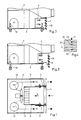
Die Erfindung soll nachfolgend anhand einer Zeichnung näher erläutert werden. Es zeigen:
- Fig. 1
- eine Draufsicht auf den Sockelinnenraum,
- Fig. 2
- eine Ausschnittsdarstellung in Seitenansicht mit eingestelltem maximalem Sockelrücksprung und minimaler Sockelhöhe,
- Fig. 3
- eine Ansicht entsprechend Fig. 2 mit eingestelltem minimalem Sockelrücksprung und maximaler Sockelhöhe,
- Fig. 4
- eine Vorderansicht der Anbringung des Lüftungsgitters in Ausschnittsdarstellung.
- Fig. 1
- a plan view of the interior of the base,
- Fig. 2
- a sectional view in side view with set maximum base recess and minimum base height,
- Fig. 3
- 2 with a set minimal base recess and maximum base height,
- Fig. 4
- a front view of the attachment of the ventilation grille in a sectional view.
In der Draufsicht nach Fig. 1 ist ein aus mehreren Winkelstegen bestehendes Lüftungsgitter 1 erkennbar, welches an zwei streifenförmigen Seitenwandteilen 2,3 gehaltert ist.In the plan view according to FIG. 1, a ventilation grille 1 consisting of several angular webs can be seen, which is held on two strip-shaped
Die Seitenwandteile 2,3 sind über die in den Figuren 2 und 3 erkennbaren Langlochverbindungen 4 mit jeweils feststehenden Innenwandteilen 5,6 verbunden und bilden in Verbindung mit der oberen Sockeltrennwand 7 und dem Bodenteil 8 einen Hauptluftführungskanal 9, welcher in dem gezeigten Ausführungsbeispiel als Zuströmkanal ausgebildet ist. Der Zustrom erfolgt dabei von der Frontseite im Mittelbereich des Lüftungsgitters 1.The
Im dem Hauptluftführungskanal 9 ist ein Lamellenverflüssiger 10 angeordnet.A
Zur Zwangsbelüftung des Lamellenverflüssigers 10 dient ein Ventilator 11, welcher die Zwangsbewegung der Hauptluftströmung anfacht.A
Zwischen den Seitenwandteilen 2,3 bzw. den feststehenden Innenwandteilen 5,6 und den seitlichen Sockelinnenwandflächen 12,13 werden Teilströmungskanäle 14,15 gebildet, in denen die Kühlluft in Gegenrichtung zum Hauptluftführungskanal 9 strömt und durch die beiden Außenbereiche des Lüftungsgitters in Pfeilrichtung wieder nach der Vorderseite abgegeben wird.
Im Umlenkströmungsbereich der Teilströme 14,15 sind je ein Kompressor 16,17 angeordnet. Zur Einstellung der Geräte- bzw. Sockelhöhe dienen Bodeneinstellschrauben 18.A
In Fig. 2 und 3 ist die Rücksprung- und Höhenanpassung des Sockels bzw. des Lüftungsgitters dargestellt.2 and 3, the return and height adjustment of the base or the ventilation grille is shown.
Bei der Ausführung nach Fig. 2 sind die beiden Seitenwandteile 2,3 in den Langlochverbindungen 4 an ihren rückwärtigen Endanschlag eingeschoben, und das Lüftungsgitter 1 ist auf die Rechteckvorsprünge 19 in seiner obersten Lageposition aufgelegt. Diese Einstellung entspricht maximalem Rücksprung und minimaler Sockelhöhe.In the embodiment according to FIG. 2, the two
Das Lüftungsgitter 1 weist dabei, wie in der Ausschnittsdarstellung nach Fig. 4 erkennbar, Trageteile 20 auf, an denen mehrere übereinanderliegende Stegteile 21 mit Winkelquerschnitt befestigt sind. Die Stegteile 21 werden auf die angepaßten Rechteckvorsprünge 19 der Seitenwandteile 2,3 aufgelegt und zweckmäßig durch Halteschrauben 22 gegenüber diesen gesichert.The ventilation grille 1 has, as can be seen in the detail view according to FIG. 4, support
Fig. 3 zeigt die Seitenwandteile 2,3 in der herausgezogenen Position mit minimalem Sockelrücksprung am vorderen Endanschlag der Langlochverbindungen 4. Da in diesem Ausführungsbeispiel eine annähernd maximale Sockelhöhe durch Einstellung der Bodeneinstellschrauben 18 vorgegeben ist, wurde das Lüftungsgitter 1 auf den Rechteckvorsprüngen 19 so tief eingehängt, daß eine Abdeckung der Sockelvorderseite nahezu bis zur Bodenauflage erreicht wird.3 shows the
Zwischen den beiden Extremlagen sind entsprechende Zwischenstellungen möglich, die bei der Horizontalverschiebung des an den Seitenwandteilen 2,3 gehalterten Lüftungsgitters 1 kontinuierlich erfolgen kann, während die Höheneinstellung stufenförmig, jeweils um die Abstandshöhe eines Rechteckvorsprungs 19, möglich ist. Die Einstellung des Lüftungsgitters hinsichtlich Höhe und Rücksprung läßt die Strömungsverhältnisse im Hauptluftführungskanal 9 und in den beiden ihn seitlich umgebenden Teilströmungskanälen 14,15 im wesentlichen unbeeinflußt.Between the two extreme positions, corresponding intermediate positions are possible, which can take place continuously during the horizontal displacement of the ventilation grille 1 held on the
Claims (5)
Applications Claiming Priority (2)
| Application Number | Priority Date | Filing Date | Title |
|---|---|---|---|
| DE9002083U | 1990-02-22 | ||
| DE9002083U DE9002083U1 (en) | 1990-02-22 | 1990-02-22 | Refrigerator or freezer |
Publications (3)
| Publication Number | Publication Date |
|---|---|
| EP0444461A2 true EP0444461A2 (en) | 1991-09-04 |
| EP0444461A3 EP0444461A3 (en) | 1992-02-12 |
| EP0444461B1 EP0444461B1 (en) | 1994-04-13 |
Family
ID=6851267
Family Applications (1)
| Application Number | Title | Priority Date | Filing Date |
|---|---|---|---|
| EP91101849A Expired - Lifetime EP0444461B1 (en) | 1990-02-22 | 1991-02-09 | Refrigerator or freezer |
Country Status (3)
| Country | Link |
|---|---|
| US (1) | US5083443A (en) |
| EP (1) | EP0444461B1 (en) |
| DE (1) | DE9002083U1 (en) |
Cited By (7)
| Publication number | Priority date | Publication date | Assignee | Title |
|---|---|---|---|---|
| EP0568809A1 (en) * | 1992-05-08 | 1993-11-10 | Liebherr-Hausgeräte Gmbh | Refrigerator and/or freezer with a base compartment |
| GB2333585A (en) * | 1998-01-23 | 1999-07-28 | Electrolux Zanussi Elettrodome | A base for a refrigerator |
| WO2009013121A2 (en) | 2007-07-24 | 2009-01-29 | BSH Bosch und Siemens Hausgeräte GmbH | Refrigerator |
| EP2292993A2 (en) | 2009-09-03 | 2011-03-09 | Liebherr-Hausgeräte Ochsenhausen GmbH | Substructure group element for a fridge and/or freezer, fridge and/or freezer and method for assembling same |
| DE102009056424A1 (en) | 2009-09-03 | 2011-03-10 | Liebherr-Hausgeräte Ochsenhausen GmbH | Subassembly element for a refrigerator and / or freezer, assembly and refrigerator and / or freezer |
| DE102009056423A1 (en) | 2009-09-03 | 2011-03-10 | Liebherr-Hausgeräte Ochsenhausen GmbH | Subassembly element for a refrigerator and / or freezer and refrigerator and / or freezer |
| DE102009060077A1 (en) * | 2009-11-18 | 2011-05-19 | Liebherr-Hausgeräte Lienz Gmbh | Subassembly element for a refrigerator and / or freezer and refrigerator and / or freezer |
Families Citing this family (11)
| Publication number | Priority date | Publication date | Assignee | Title |
|---|---|---|---|---|
| US5251461A (en) * | 1992-09-18 | 1993-10-12 | Carrier Corporation | Grille for packaged terminal air conditioner |
| US5428973A (en) * | 1992-11-13 | 1995-07-04 | Kabushiki Kaisha Toshiba | Refrigerator with meandering air duct for wire and tube condenser |
| USD379467S (en) * | 1995-12-22 | 1997-05-27 | White Consolidated Industries, Inc. | Refrigerator grille |
| US6543250B1 (en) | 2001-11-27 | 2003-04-08 | Dometic Corporation | Installation template for a mobile refrigerator |
| DE10207281B4 (en) * | 2002-02-21 | 2006-11-09 | BSH Bosch und Siemens Hausgeräte GmbH | Standing domestic appliance |
| KR100539528B1 (en) * | 2002-07-24 | 2005-12-30 | 엘지전자 주식회사 | built-in type refrigerator |
| KR101726223B1 (en) * | 2010-09-16 | 2017-04-12 | 엘지전자 주식회사 | Refrigerator |
| US20120067075A1 (en) * | 2010-09-16 | 2012-03-22 | Lg Electronics Inc. | Refrigerator |
| US20130255305A1 (en) * | 2012-03-28 | 2013-10-03 | Brian S. Kim | Air duct device for refrigerator |
| KR102103951B1 (en) * | 2012-07-06 | 2020-04-24 | 삼성전자주식회사 | Refrigerator |
| CN115540471B (en) * | 2021-06-30 | 2025-10-03 | 青岛海尔电冰箱有限公司 | Refrigerator door assembly, refrigerator and integrated cabinet |
Family Cites Families (6)
| Publication number | Priority date | Publication date | Assignee | Title |
|---|---|---|---|---|
| DE2458981C2 (en) * | 1974-12-13 | 1985-04-18 | Bosch-Siemens Hausgeräte GmbH, 7000 Stuttgart | Refrigerated cabinets, especially no-frost refrigerators |
| DE2625202C3 (en) * | 1976-06-04 | 1983-12-15 | Bosch-Siemens Hausgeräte GmbH, 7000 Stuttgart | Household appliance, e.g. dishwasher, with a base recess on the front |
| CH637527A5 (en) * | 1979-06-19 | 1983-08-15 | Koch Ag | Ice-making appliance |
| DE8210690U1 (en) * | 1982-04-15 | 1982-06-24 | Bosch-Siemens Hausgeräte GmbH, 7000 Stuttgart | Built-in device, especially a refrigerator or freezer that can be built into a kitchen unit |
| US4821530A (en) * | 1988-05-13 | 1989-04-18 | Ledbetter Ricky G | Air-conditioning refrigerator |
| DE8906719U1 (en) * | 1989-06-01 | 1989-07-13 | Bosch-Siemens Hausgeräte GmbH, 8000 München | Cooling appliance, in particular a refrigerator or freezer that can be inserted into a built-in kitchen unit equipped with a base |
-
1990
- 1990-02-22 DE DE9002083U patent/DE9002083U1/en not_active Expired - Lifetime
-
1991
- 1991-02-09 EP EP91101849A patent/EP0444461B1/en not_active Expired - Lifetime
- 1991-02-20 US US07/657,820 patent/US5083443A/en not_active Expired - Fee Related
Cited By (13)
| Publication number | Priority date | Publication date | Assignee | Title |
|---|---|---|---|---|
| EP0568809A1 (en) * | 1992-05-08 | 1993-11-10 | Liebherr-Hausgeräte Gmbh | Refrigerator and/or freezer with a base compartment |
| GB2333585A (en) * | 1998-01-23 | 1999-07-28 | Electrolux Zanussi Elettrodome | A base for a refrigerator |
| GB2333585B (en) * | 1998-01-23 | 2001-09-12 | Electrolux Zanussi Elettrodome | Refrigerating appliance with improved air flow arrangement |
| WO2009013121A2 (en) | 2007-07-24 | 2009-01-29 | BSH Bosch und Siemens Hausgeräte GmbH | Refrigerator |
| WO2009013121A3 (en) * | 2007-07-24 | 2009-05-28 | Bsh Bosch Siemens Hausgeraete | Refrigerator |
| DE102009056424A1 (en) | 2009-09-03 | 2011-03-10 | Liebherr-Hausgeräte Ochsenhausen GmbH | Subassembly element for a refrigerator and / or freezer, assembly and refrigerator and / or freezer |
| EP2292993A2 (en) | 2009-09-03 | 2011-03-09 | Liebherr-Hausgeräte Ochsenhausen GmbH | Substructure group element for a fridge and/or freezer, fridge and/or freezer and method for assembling same |
| DE102009056426A1 (en) | 2009-09-03 | 2011-03-10 | Liebherr-Hausgeräte Ochsenhausen GmbH | Sub-assembly element for a refrigerator and / or freezer, refrigerator and / or freezer and method for mounting a refrigerator and / or freezer |
| DE102009056423A1 (en) | 2009-09-03 | 2011-03-10 | Liebherr-Hausgeräte Ochsenhausen GmbH | Subassembly element for a refrigerator and / or freezer and refrigerator and / or freezer |
| EP2317259A2 (en) | 2009-09-03 | 2011-05-04 | Liebherr-Hausgeräte Ochsenhausen GmbH | Substructure group element for a fridge and/or freezer and fridge and/or freezer |
| EP2317258A2 (en) | 2009-09-03 | 2011-05-04 | Liebherr-Hausgeräte Ochsenhausen GmbH | Substructure group element for a fridge and/or freezer, assembly and fridge and/or freezer |
| US9115926B2 (en) | 2009-09-03 | 2015-08-25 | Liebherr-Hausgerate Ochsenhausen Gmbh | Subassembly for a refrigerating and/or freezing apparatus, refrigerating and/or freezing apparatus and process for assembly of a refrigerating and/or freezing apparatus |
| DE102009060077A1 (en) * | 2009-11-18 | 2011-05-19 | Liebherr-Hausgeräte Lienz Gmbh | Subassembly element for a refrigerator and / or freezer and refrigerator and / or freezer |
Also Published As
| Publication number | Publication date |
|---|---|
| US5083443A (en) | 1992-01-28 |
| EP0444461A3 (en) | 1992-02-12 |
| EP0444461B1 (en) | 1994-04-13 |
| DE9002083U1 (en) | 1990-04-19 |
Similar Documents
| Publication | Publication Date | Title |
|---|---|---|
| EP0444461B1 (en) | Refrigerator or freezer | |
| EP1155269A1 (en) | Refrigeration unit for fitting in a furniture recess | |
| EP0271706B1 (en) | Nozzle for the aeration of windows | |
| WO1982003114A1 (en) | Air conditionned room and method for using same | |
| DE8210690U1 (en) | Built-in device, especially a refrigerator or freezer that can be built into a kitchen unit | |
| DE1501232A1 (en) | Air distributor for refrigerated counters | |
| EP0379188A2 (en) | Device for aeration and deaeration | |
| DE2138539C3 (en) | Air outlet device | |
| EP4118388A1 (en) | Refrigeration appliance having an air distributor | |
| AT391016B (en) | VENTILATION DEVICE FOR INSTALLATION IN WINDOWS AND / OR IN OTHER WALL OPENINGS OF BUILDINGS | |
| DE4210279A1 (en) | Displacement air outlet for ventilation and air conditioning systems | |
| EP0659367B1 (en) | Household appliance for mounting in a kitchen unit | |
| EP0609727A1 (en) | Fan casing for the arrangement in a passage opening | |
| DD299449B5 (en) | K} hlger {t, in particular in a fitted kitchens equipped with a base K} hl or freezer | |
| DE2105769A1 (en) | Slot fan for installation in building ceilings | |
| EP2185875B1 (en) | Refrigerator | |
| EP0803684A2 (en) | Multiple-plate radiator | |
| DE4429144A1 (en) | Slot outlet esp. in housing or shaft | |
| DE102008054995A1 (en) | Household refrigerator, has air filter that is arranged in area of inlet and/or outlet opening, and circulating device e.g. exhaust unit or blower unit, provided in cooling channel for supplying or exhausting air | |
| DE3236980C2 (en) | Refrigerated counter | |
| DE1105587B (en) | Air duct for ventilation systems | |
| DE3347227C2 (en) | ||
| DE69309746T2 (en) | Fan | |
| DE10008598B4 (en) | jet | |
| DE1604159C3 (en) | Device for shielding a room, in particular a car wash |
Legal Events
| Date | Code | Title | Description |
|---|---|---|---|
| PUAI | Public reference made under article 153(3) epc to a published international application that has entered the european phase |
Free format text: ORIGINAL CODE: 0009012 |
|
| AK | Designated contracting states |
Kind code of ref document: A2 Designated state(s): FR IT SE |
|
| PUAL | Search report despatched |
Free format text: ORIGINAL CODE: 0009013 |
|
| AK | Designated contracting states |
Kind code of ref document: A3 Designated state(s): FR IT SE |
|
| 17P | Request for examination filed |
Effective date: 19920320 |
|
| 17Q | First examination report despatched |
Effective date: 19930715 |
|
| GRAA | (expected) grant |
Free format text: ORIGINAL CODE: 0009210 |
|
| ITF | It: translation for a ep patent filed | ||
| AK | Designated contracting states |
Kind code of ref document: B1 Designated state(s): FR IT SE |
|
| ET | Fr: translation filed | ||
| EAL | Se: european patent in force in sweden |
Ref document number: 91101849.7 |
|
| PLBE | No opposition filed within time limit |
Free format text: ORIGINAL CODE: 0009261 |
|
| STAA | Information on the status of an ep patent application or granted ep patent |
Free format text: STATUS: NO OPPOSITION FILED WITHIN TIME LIMIT |
|
| 26N | No opposition filed | ||
| PGFP | Annual fee paid to national office [announced via postgrant information from national office to epo] |
Ref country code: FR Payment date: 20040218 Year of fee payment: 14 |
|
| PGFP | Annual fee paid to national office [announced via postgrant information from national office to epo] |
Ref country code: SE Payment date: 20040227 Year of fee payment: 14 |
|
| PG25 | Lapsed in a contracting state [announced via postgrant information from national office to epo] |
Ref country code: IT Free format text: LAPSE BECAUSE OF NON-PAYMENT OF DUE FEES;WARNING: LAPSES OF ITALIAN PATENTS WITH EFFECTIVE DATE BEFORE 2007 MAY HAVE OCCURRED AT ANY TIME BEFORE 2007. THE CORRECT EFFECTIVE DATE MAY BE DIFFERENT FROM THE ONE RECORDED. Effective date: 20050209 |
|
| PG25 | Lapsed in a contracting state [announced via postgrant information from national office to epo] |
Ref country code: SE Free format text: LAPSE BECAUSE OF NON-PAYMENT OF DUE FEES Effective date: 20050210 |
|
| EUG | Se: european patent has lapsed | ||
| PG25 | Lapsed in a contracting state [announced via postgrant information from national office to epo] |
Ref country code: FR Free format text: LAPSE BECAUSE OF NON-PAYMENT OF DUE FEES Effective date: 20051031 |
|
| REG | Reference to a national code |
Ref country code: FR Ref legal event code: ST Effective date: 20051031 |