EP0444467A1 - A city refuse collector vehicle - Google Patents
A city refuse collector vehicle Download PDFInfo
- Publication number
- EP0444467A1 EP0444467A1 EP91101931A EP91101931A EP0444467A1 EP 0444467 A1 EP0444467 A1 EP 0444467A1 EP 91101931 A EP91101931 A EP 91101931A EP 91101931 A EP91101931 A EP 91101931A EP 0444467 A1 EP0444467 A1 EP 0444467A1
- Authority
- EP
- European Patent Office
- Prior art keywords
- shaft
- gear wheel
- drive
- fixed
- endothermic engine
- Prior art date
- Legal status (The legal status is an assumption and is not a legal conclusion. Google has not performed a legal analysis and makes no representation as to the accuracy of the status listed.)
- Withdrawn
Links
Images
Classifications
-
- B—PERFORMING OPERATIONS; TRANSPORTING
- B60—VEHICLES IN GENERAL
- B60K—ARRANGEMENT OR MOUNTING OF PROPULSION UNITS OR OF TRANSMISSIONS IN VEHICLES; ARRANGEMENT OR MOUNTING OF PLURAL DIVERSE PRIME-MOVERS IN VEHICLES; AUXILIARY DRIVES FOR VEHICLES; INSTRUMENTATION OR DASHBOARDS FOR VEHICLES; ARRANGEMENTS IN CONNECTION WITH COOLING, AIR INTAKE, GAS EXHAUST OR FUEL SUPPLY OF PROPULSION UNITS IN VEHICLES
- B60K6/00—Arrangement or mounting of plural diverse prime-movers for mutual or common propulsion, e.g. hybrid propulsion systems comprising electric motors and internal combustion engines
- B60K6/20—Arrangement or mounting of plural diverse prime-movers for mutual or common propulsion, e.g. hybrid propulsion systems comprising electric motors and internal combustion engines the prime-movers consisting of electric motors and internal combustion engines, e.g. HEVs
- B60K6/22—Arrangement or mounting of plural diverse prime-movers for mutual or common propulsion, e.g. hybrid propulsion systems comprising electric motors and internal combustion engines the prime-movers consisting of electric motors and internal combustion engines, e.g. HEVs characterised by apparatus, components or means specially adapted for HEVs
- B60K6/36—Arrangement or mounting of plural diverse prime-movers for mutual or common propulsion, e.g. hybrid propulsion systems comprising electric motors and internal combustion engines the prime-movers consisting of electric motors and internal combustion engines, e.g. HEVs characterised by apparatus, components or means specially adapted for HEVs characterised by the transmission gearings
-
- B—PERFORMING OPERATIONS; TRANSPORTING
- B60—VEHICLES IN GENERAL
- B60K—ARRANGEMENT OR MOUNTING OF PROPULSION UNITS OR OF TRANSMISSIONS IN VEHICLES; ARRANGEMENT OR MOUNTING OF PLURAL DIVERSE PRIME-MOVERS IN VEHICLES; AUXILIARY DRIVES FOR VEHICLES; INSTRUMENTATION OR DASHBOARDS FOR VEHICLES; ARRANGEMENTS IN CONNECTION WITH COOLING, AIR INTAKE, GAS EXHAUST OR FUEL SUPPLY OF PROPULSION UNITS IN VEHICLES
- B60K6/00—Arrangement or mounting of plural diverse prime-movers for mutual or common propulsion, e.g. hybrid propulsion systems comprising electric motors and internal combustion engines
- B60K6/20—Arrangement or mounting of plural diverse prime-movers for mutual or common propulsion, e.g. hybrid propulsion systems comprising electric motors and internal combustion engines the prime-movers consisting of electric motors and internal combustion engines, e.g. HEVs
- B60K6/42—Arrangement or mounting of plural diverse prime-movers for mutual or common propulsion, e.g. hybrid propulsion systems comprising electric motors and internal combustion engines the prime-movers consisting of electric motors and internal combustion engines, e.g. HEVs characterised by the architecture of the hybrid electric vehicle
- B60K6/48—Parallel type
-
- B—PERFORMING OPERATIONS; TRANSPORTING
- B65—CONVEYING; PACKING; STORING; HANDLING THIN OR FILAMENTARY MATERIAL
- B65F—GATHERING OR REMOVAL OF DOMESTIC OR LIKE REFUSE
- B65F3/00—Vehicles particularly adapted for collecting refuse
-
- F—MECHANICAL ENGINEERING; LIGHTING; HEATING; WEAPONS; BLASTING
- F02—COMBUSTION ENGINES; HOT-GAS OR COMBUSTION-PRODUCT ENGINE PLANTS
- F02B—INTERNAL-COMBUSTION PISTON ENGINES; COMBUSTION ENGINES IN GENERAL
- F02B3/00—Engines characterised by air compression and subsequent fuel addition
- F02B3/06—Engines characterised by air compression and subsequent fuel addition with compression ignition
-
- Y—GENERAL TAGGING OF NEW TECHNOLOGICAL DEVELOPMENTS; GENERAL TAGGING OF CROSS-SECTIONAL TECHNOLOGIES SPANNING OVER SEVERAL SECTIONS OF THE IPC; TECHNICAL SUBJECTS COVERED BY FORMER USPC CROSS-REFERENCE ART COLLECTIONS [XRACs] AND DIGESTS
- Y02—TECHNOLOGIES OR APPLICATIONS FOR MITIGATION OR ADAPTATION AGAINST CLIMATE CHANGE
- Y02T—CLIMATE CHANGE MITIGATION TECHNOLOGIES RELATED TO TRANSPORTATION
- Y02T10/00—Road transport of goods or passengers
- Y02T10/60—Other road transportation technologies with climate change mitigation effect
- Y02T10/62—Hybrid vehicles
Definitions
- the invention concerns a city refuse collector vehicle.
- Collector vehicles which collect the refuses contained in caissons spread in a city area and move them to an authorized discharge area.
- the power required for driving said collector vehicles and some service devices is generally supplied from an endothermic engine, still more generally from a Diesel engine.
- Collector vehicles are also known wherein said power is supplied from an electric motor fed from batteries as well as wherein power for service devices is supplied from an outer power source available at each station along the vehicle path.
- This present invention obviates all said drawbacks while completely settles the problem of collecting refuses, compacting them in the collector vehicle, moving them to a discharge area and discharging them.
- the invented collector vehicle comprises all parts provided in a conventional collector vehicle, in particular an endothermic engine, a gearbox, a clutch and service devices and, as claimed, comprises a selective mechanical transmission assembly that provides for the drive action alternatively from a first motor means or from a second motor means, to driver's choice, said first motor means being said conventional endothermic engine and said second motor means being a direct current electric motor fed from an onboard battery and provided with its own clutch, this electric motor being adapted to carry out the alternative work of battery recharging.
- said selective mechanical transmission assembly comprises: a first gear wheel on an axially fixed shaft which receives the drive from said endothermic engine, on one side, and is connected with drive transmission means to the driving wheels, on the other side; a second gear wheel on an axially fixed shaft which gear meshes said first gear wheel; a third gear wheel on an axially sliding shaft under the control of a first coupling means actuated by a driver in order to mesh or disengage said second gear wheel, the latter shaft being connected with a second transmission means to drive said electric motor; a fourth gear wheel on an axially sliding shaft under the control of a second coupling means actuated by said driver in order to mesh or disengage said second gear wheel, the latter shaft being connected with a compressor which recharges the compressed air reservoirs and with a pump which actuates the power steering.
- said selective mechanical transmission assembly is adapted alternatively to: a) be connected with said endothermic engine and disconnected with said third gear wheel (so, disconnected with the electric motor) and transmit the drive from the endothermic engine to the driving wheels; b) be disconnected with the endothermic engine, have said third gear wheel meshing said second gear wheel and receive the drive from said electric motor, so transmitting drive to a propeller shaft and driving wheels.
- said selective mechanical transmission assembly is able to transmit the drive from the endothermic engine to said electric motor so that the latter is made to rotate to work as a generator that charges the batteries which feed the electric motor. This stage takes place when the driver keeps the electric motor idle, the endothermic engine alive, the latter coupled with said first gear wheel and said third gear wheel meshing said second gear wheel.
- the main advantages afforded by the invention reside in that all the work the collector vehicle carries out in the city may be supplied from the electric motor, which avoids pollution, and the distance from the city to the discharge area may be covered using the endothermic engine at a convenient velocity.
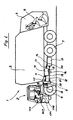
- Fig. 1 shows a refuse collector 1 and conventional parts thereof as: a driver's cab 2, a refuse loading caisson 3, a rear caisson 4 which cantains service devices 5 for handling refuse caissons and refuses themselves , steering wheels 6, driving wheels 7, a Diesel engine 8 with its clutch 9 and a gear box 10 having the drive input means 11 connected with a first propeller shaft 12 for receiving the drive, having the drive output means 13 connected with a second propeller shaft 14 for transmitting the drive to the driving wheels 7 and having a third transmission means 15 for actuating a hydraulic pump 16 which supplies power for actuating the service devices 5.
- the refuse collector comprises a direct current motor 17 (d.c. motor) which is fed from a onboard electric battery 18.
- a fourth propeller shaft 19 has an end connected with said d.c. motor 17, through an electromagnetic clutch 20, and the other end connected with said selective mechanical transmission assembly 21 which is diagrammatically detailed in Fig. 2.
- CJ shows Cardan joints connecting a shaft with its respective shaft or means;
- VCH shows a handle for controlling the velocity of the d.c. motor 17;
- ECP shows a driver's pedal for controlling the electromagnetic clutch;
- CP1 shows a push button for controlling by pneumatic means the first coupling means 22 (see Fig. 2) and
- CP2 shows a push button for controlling by pneumatic means the second coupling means 23 (see Fig. 2), all these control means being conveniently located in the driver's cab.
- the coupling means 22 (only diagrammatically shown) with the electric motor is disconnected by pneumatic means and reconnected by a spring
- the second coupling means 23 (only diagrammatically shown) in connected by pneumatic means and disconnected by a spring.
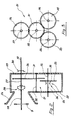
- Fig. 2 shows a cup 24 which receives a clutch 9 of the Diesel engine 8 and is associated to a case 25 containing said selective mechanical transmission assembly 21 composed by: a first gear wheel 26 whose axially fixed shaft 27 is coupled through a third coupling means 29 with the output clutch shaft 28, at one side, and is connected with said first propeller shaft 12 at the other side through a flange 30 which transmits the drive to the gear box 10; an axially fixed shaft 32 carrying a second gear wheel 31 meshing said first gear wheel 26; a third gear wheel 33 on a shaft 34 sliding axially under the control of a second coupling means 22 to mesh or disengage said second gear wheel 31, the shaft 34 for said third gear wheel 33 being connected with the fourth propeller shaft 19 which actuates the d.c.
- shaft 36 may be connected with an assembly for transmitting the drive to said compressor and said pump, as well as that one end of shaft 36 may be connected with said compressor and the other end with said pump.
- Fig. 3 shows the relative position of the four gear wheels 26, 31, 33, 35 and respective shafts 27, 32, 34, and 36, all these wheels and shafts being part of the selective mechanical transmission assembly 21.
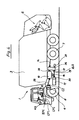
- Fig. 4 shows the selective mechanical transmission assembly 21 located between said gear box 10 and shaft 14 which transmits the drive to the drive wheels 7 instead of being located between the clutch of the endothermic engine 8 and the gear box 10, as in the embodiment of Fig. 1.
- a pump 16A is provided for actuating the service devices, which pump is connected with the left end of shaft 36, while a pump 37, for actuating the power steering, is connected with the right end of same shaft 36 in said selective mechanical transmission assembly 21. Substantially, all those parts are visible that are shown and described with reference to Fig.
Landscapes
- Engineering & Computer Science (AREA)
- Mechanical Engineering (AREA)
- Chemical & Material Sciences (AREA)
- Combustion & Propulsion (AREA)
- Transportation (AREA)
- Auxiliary Drives, Propulsion Controls, And Safety Devices (AREA)
Applications Claiming Priority (2)
| Application Number | Priority Date | Filing Date | Title |
|---|---|---|---|
| IT19405A IT1239074B (it) | 1990-02-19 | 1990-02-19 | Autocompattatore per rifiuti urbani |
| IT1940590 | 1990-02-19 |
Publications (1)
| Publication Number | Publication Date |
|---|---|
| EP0444467A1 true EP0444467A1 (en) | 1991-09-04 |
Family
ID=11157467
Family Applications (1)
| Application Number | Title | Priority Date | Filing Date |
|---|---|---|---|
| EP91101931A Withdrawn EP0444467A1 (en) | 1990-02-19 | 1991-02-12 | A city refuse collector vehicle |
Country Status (2)
| Country | Link |
|---|---|
| EP (1) | EP0444467A1 (it) |
| IT (1) | IT1239074B (it) |
Cited By (9)
| Publication number | Priority date | Publication date | Assignee | Title |
|---|---|---|---|---|
| FR2699127A1 (fr) * | 1992-12-11 | 1994-06-17 | Semat | Dispositif de changement de mode de fonctionnement pour un véhicule bimode thermique/électrique et véhicle bimode comportant un tel dispositif. |
| GB2324772A (en) * | 1995-09-29 | 1998-11-04 | Fuji Heavy Ind Ltd | Vehicle with hybrid propulsion system |
| US6644427B2 (en) * | 2001-04-06 | 2003-11-11 | Ise Research Corporation | System and method for providing parallel power in a hybrid-electric vehicle |
| EP1203683A3 (en) * | 2000-11-03 | 2004-02-25 | Shenzhen Minghua Environmental Protection Vehicle Co., Ltd. | Hybrid electric environmental protection automobile |
| WO2006037041A1 (en) * | 2004-09-27 | 2006-04-06 | Oshkosh Truck Corporation | Engine and generator orientation within a hybrid vehicle |
| DE202007002769U1 (de) * | 2007-01-22 | 2008-05-29 | Faun Umwelttechnik Gmbh & Co. Kg | Drehtrommelantrieb |
| ES2302457A1 (es) * | 2006-12-20 | 2008-07-01 | Avia Ingenieria Y Diseño S.L. | Bastidor para camiones polivalente. |
| ITTO20100573A1 (it) * | 2010-07-02 | 2012-01-03 | Giletta Spa | Unita' di spargimento per materiale antighiaccio e relativo veicolo |
| EP2537695A1 (en) * | 2011-06-20 | 2012-12-26 | AISIN AI Co., Ltd. | Drive unit for hybrid vehicle |
Citations (4)
| Publication number | Priority date | Publication date | Assignee | Title |
|---|---|---|---|---|
| DE2029763A1 (de) * | 1969-06-17 | 1970-12-23 | The Warner & Swasey Company, Cleveland, Ohio (V.St.A.) | Fahrzeug zur Handhabung von Materialien |
| DE2345018A1 (de) * | 1972-09-27 | 1974-04-04 | Saviem | Fahrzeugtransmission |
| DE2805594A1 (de) * | 1978-02-10 | 1979-08-16 | Daimler Benz Ag | Von einer brennkraftmaschine antreibbares fahrzeug mit einer hydraulischen hubvorrichtung |
| EP0248178A1 (de) * | 1986-06-06 | 1987-12-09 | MAN Nutzfahrzeuge Aktiengesellschaft | Kraftfahrzeug mit einer Antriebseinrichtung für eine Hinterachse |
-
1990
- 1990-02-19 IT IT19405A patent/IT1239074B/it active IP Right Grant
-
1991
- 1991-02-12 EP EP91101931A patent/EP0444467A1/en not_active Withdrawn
Patent Citations (4)
| Publication number | Priority date | Publication date | Assignee | Title |
|---|---|---|---|---|
| DE2029763A1 (de) * | 1969-06-17 | 1970-12-23 | The Warner & Swasey Company, Cleveland, Ohio (V.St.A.) | Fahrzeug zur Handhabung von Materialien |
| DE2345018A1 (de) * | 1972-09-27 | 1974-04-04 | Saviem | Fahrzeugtransmission |
| DE2805594A1 (de) * | 1978-02-10 | 1979-08-16 | Daimler Benz Ag | Von einer brennkraftmaschine antreibbares fahrzeug mit einer hydraulischen hubvorrichtung |
| EP0248178A1 (de) * | 1986-06-06 | 1987-12-09 | MAN Nutzfahrzeuge Aktiengesellschaft | Kraftfahrzeug mit einer Antriebseinrichtung für eine Hinterachse |
Cited By (17)
| Publication number | Priority date | Publication date | Assignee | Title |
|---|---|---|---|---|
| FR2699127A1 (fr) * | 1992-12-11 | 1994-06-17 | Semat | Dispositif de changement de mode de fonctionnement pour un véhicule bimode thermique/électrique et véhicle bimode comportant un tel dispositif. |
| GB2324772A (en) * | 1995-09-29 | 1998-11-04 | Fuji Heavy Ind Ltd | Vehicle with hybrid propulsion system |
| GB2324772B (en) * | 1995-09-29 | 1999-03-17 | Fuji Heavy Ind Ltd | Drive unit for hybrid vehicle |
| EP1203683A3 (en) * | 2000-11-03 | 2004-02-25 | Shenzhen Minghua Environmental Protection Vehicle Co., Ltd. | Hybrid electric environmental protection automobile |
| US6644427B2 (en) * | 2001-04-06 | 2003-11-11 | Ise Research Corporation | System and method for providing parallel power in a hybrid-electric vehicle |
| US7419021B2 (en) | 2004-09-27 | 2008-09-02 | Oshkosh Truck Corporation | Engine and generator orientation within a hybrid vehicle |
| WO2006037041A1 (en) * | 2004-09-27 | 2006-04-06 | Oshkosh Truck Corporation | Engine and generator orientation within a hybrid vehicle |
| ES2302457A1 (es) * | 2006-12-20 | 2008-07-01 | Avia Ingenieria Y Diseño S.L. | Bastidor para camiones polivalente. |
| ES2302457B1 (es) * | 2006-12-20 | 2009-08-17 | Avia Ingenieria Y Diseño S.L. | Bastidor para camiones polivalente. |
| DE202007002769U1 (de) * | 2007-01-22 | 2008-05-29 | Faun Umwelttechnik Gmbh & Co. Kg | Drehtrommelantrieb |
| ITTO20100573A1 (it) * | 2010-07-02 | 2012-01-03 | Giletta Spa | Unita' di spargimento per materiale antighiaccio e relativo veicolo |
| WO2012001508A1 (en) * | 2010-07-02 | 2012-01-05 | Giletta S.P.A. | Spreader unit for a de-icing material and respective vehicle |
| RU2572761C2 (ru) * | 2010-07-02 | 2016-01-20 | Джилетта С.П.А. | Распределительный блок для материала для борьбы с обледенением и соответствующее транспортное средство |
| US9284703B2 (en) | 2010-07-02 | 2016-03-15 | Giletta S.P.A. | Spreader unit for de-icing material and respective vehicle |
| EP2537695A1 (en) * | 2011-06-20 | 2012-12-26 | AISIN AI Co., Ltd. | Drive unit for hybrid vehicle |
| JP2013001330A (ja) * | 2011-06-20 | 2013-01-07 | Aisin Ai Co Ltd | ハイブリッド車用駆動装置 |
| US8534162B2 (en) | 2011-06-20 | 2013-09-17 | Aisin Ai Co., Ltd. | Drive unit for hybrid vehicle |
Also Published As
| Publication number | Publication date |
|---|---|
| IT1239074B (it) | 1993-09-21 |
| IT9019405A0 (it) | 1990-02-19 |
| IT9019405A1 (it) | 1991-08-19 |
Similar Documents
| Publication | Publication Date | Title |
|---|---|---|
| AU721389B2 (en) | Drive system for hybrid electric vehicle | |
| US4199037A (en) | Electric automobile | |
| US6857985B2 (en) | Hybrid vehicle system | |
| CN101052542B (zh) | 具有动力取力机构驱动车辆附件的混合车辆动力系统 | |
| EP1373758B1 (en) | Transfer case for hybrid vehicle | |
| US7255187B2 (en) | Axle assembly with parallel drive system for electric hybrid vehicles | |
| EP0812717A3 (en) | Control system for hybrid vehicles | |
| US6658852B2 (en) | Motor vehicle drive | |
| US7743859B2 (en) | Hybrid drivetrains for trailers | |
| EP0510582A2 (en) | Vehicle powerplant featuring thermal and electrical drive means | |
| US8672066B2 (en) | Agricultural vehicle and method of operation | |
| US5147003A (en) | Composite road vehicle with electric and thermal propulsion means | |
| US5224563A (en) | Energy regenerating mechanism of an automobile | |
| US4222450A (en) | Electrical drive for automobile | |
| EP0444467A1 (en) | A city refuse collector vehicle | |
| JPH11506517A (ja) | ハイブリッド電気車両用エネルギー分配方法 | |
| EP1400386A2 (en) | Hybrid vehicle | |
| EP1236603A3 (en) | A driving apparatus for controlling gear shifting in a hybrid vehicle | |
| US20120273285A1 (en) | Method of converting, storing and utilizing potential energy at a worksite and system using the same | |
| EP1431618A3 (en) | Transmission for wheel type working vehicle | |
| GB1584278A (en) | Omnibuses | |
| EP0347142A1 (en) | Road-sweeping vehicle | |
| US8056661B2 (en) | Motor vehicle with system for conditioning power take-off enablement on an engine compartment being closed | |
| WO2004069573A1 (en) | Hybrid vehicle with auxilliary generator | |
| EP0458005B1 (en) | Energy regenerating mechanism of an elektric automobile |
Legal Events
| Date | Code | Title | Description |
|---|---|---|---|
| PUAI | Public reference made under article 153(3) epc to a published international application that has entered the european phase |
Free format text: ORIGINAL CODE: 0009012 |
|
| AK | Designated contracting states |
Kind code of ref document: A1 Designated state(s): BE CH DE DK ES FR GB LI LU NL |
|
| 17P | Request for examination filed |
Effective date: 19920212 |
|
| 17Q | First examination report despatched |
Effective date: 19920515 |
|
| STAA | Information on the status of an ep patent application or granted ep patent |
Free format text: STATUS: THE APPLICATION IS DEEMED TO BE WITHDRAWN |
|
| 18D | Application deemed to be withdrawn |
Effective date: 19930304 |