EP0444480B1 - Procédé pour le soudage par coulée intermédiaire de rails recuits de microperlitisation - Google Patents
Procédé pour le soudage par coulée intermédiaire de rails recuits de microperlitisation Download PDFInfo
- Publication number
- EP0444480B1 EP0444480B1 EP91102086A EP91102086A EP0444480B1 EP 0444480 B1 EP0444480 B1 EP 0444480B1 EP 91102086 A EP91102086 A EP 91102086A EP 91102086 A EP91102086 A EP 91102086A EP 0444480 B1 EP0444480 B1 EP 0444480B1
- Authority
- EP
- European Patent Office
- Prior art keywords
- rail
- rails
- welding
- hardness
- heat
- Prior art date
- Legal status (The legal status is an assumption and is not a legal conclusion. Google has not performed a legal analysis and makes no representation as to the accuracy of the status listed.)
- Expired - Lifetime
Links
- 238000003466 welding Methods 0.000 title claims abstract description 31
- 238000000034 method Methods 0.000 title claims abstract description 22
- 230000008569 process Effects 0.000 title abstract description 10
- 238000005266 casting Methods 0.000 claims abstract description 32
- 229910000831 Steel Inorganic materials 0.000 claims abstract description 22
- 239000010959 steel Substances 0.000 claims abstract description 22
- 239000002826 coolant Substances 0.000 claims abstract description 14
- 238000001816 cooling Methods 0.000 claims description 17
- 229910052751 metal Inorganic materials 0.000 claims description 4
- 239000002184 metal Substances 0.000 claims description 4
- 238000007711 solidification Methods 0.000 claims description 2
- 230000008023 solidification Effects 0.000 claims description 2
- 239000000463 material Substances 0.000 abstract 1
- 238000007789 sealing Methods 0.000 abstract 1
- 239000000203 mixture Substances 0.000 description 9
- 239000000126 substance Substances 0.000 description 6
- 230000015572 biosynthetic process Effects 0.000 description 5
- 238000009826 distribution Methods 0.000 description 5
- 238000010438 heat treatment Methods 0.000 description 5
- 238000002844 melting Methods 0.000 description 4
- 230000008018 melting Effects 0.000 description 4
- 229910001562 pearlite Inorganic materials 0.000 description 4
- 238000005096 rolling process Methods 0.000 description 4
- 229910052799 carbon Inorganic materials 0.000 description 3
- 230000007423 decrease Effects 0.000 description 3
- XLYOFNOQVPJJNP-UHFFFAOYSA-N water Substances O XLYOFNOQVPJJNP-UHFFFAOYSA-N 0.000 description 3
- 229910045601 alloy Inorganic materials 0.000 description 2
- 239000000956 alloy Substances 0.000 description 2
- 230000002349 favourable effect Effects 0.000 description 2
- 229910052748 manganese Inorganic materials 0.000 description 2
- 239000011572 manganese Substances 0.000 description 2
- 230000009466 transformation Effects 0.000 description 2
- 230000007704 transition Effects 0.000 description 2
- 229910052720 vanadium Inorganic materials 0.000 description 2
- OKTJSMMVPCPJKN-UHFFFAOYSA-N Carbon Chemical compound [C] OKTJSMMVPCPJKN-UHFFFAOYSA-N 0.000 description 1
- VYZAMTAEIAYCRO-UHFFFAOYSA-N Chromium Chemical compound [Cr] VYZAMTAEIAYCRO-UHFFFAOYSA-N 0.000 description 1
- 229910001208 Crucible steel Inorganic materials 0.000 description 1
- PWHULOQIROXLJO-UHFFFAOYSA-N Manganese Chemical compound [Mn] PWHULOQIROXLJO-UHFFFAOYSA-N 0.000 description 1
- 239000000654 additive Substances 0.000 description 1
- 238000005275 alloying Methods 0.000 description 1
- 238000007133 aluminothermic reaction Methods 0.000 description 1
- 238000000137 annealing Methods 0.000 description 1
- 239000011324 bead Substances 0.000 description 1
- 238000005452 bending Methods 0.000 description 1
- 229910052804 chromium Inorganic materials 0.000 description 1
- 238000010276 construction Methods 0.000 description 1
- 230000003247 decreasing effect Effects 0.000 description 1
- 238000005516 engineering process Methods 0.000 description 1
- 230000004927 fusion Effects 0.000 description 1
- 230000006872 improvement Effects 0.000 description 1
- 230000007246 mechanism Effects 0.000 description 1
- 239000011541 reaction mixture Substances 0.000 description 1
- 238000010079 rubber tapping Methods 0.000 description 1
- 238000010008 shearing Methods 0.000 description 1
- 239000000161 steel melt Substances 0.000 description 1
- LEONUFNNVUYDNQ-UHFFFAOYSA-N vanadium atom Chemical compound [V] LEONUFNNVUYDNQ-UHFFFAOYSA-N 0.000 description 1
Images

Classifications
-
- B—PERFORMING OPERATIONS; TRANSPORTING
- B23—MACHINE TOOLS; METAL-WORKING NOT OTHERWISE PROVIDED FOR
- B23K—SOLDERING OR UNSOLDERING; WELDING; CLADDING OR PLATING BY SOLDERING OR WELDING; CUTTING BY APPLYING HEAT LOCALLY, e.g. FLAME CUTTING; WORKING BY LASER BEAM
- B23K23/00—Alumino-thermic welding
-
- E—FIXED CONSTRUCTIONS
- E01—CONSTRUCTION OF ROADS, RAILWAYS, OR BRIDGES
- E01B—PERMANENT WAY; PERMANENT-WAY TOOLS; MACHINES FOR MAKING RAILWAYS OF ALL KINDS
- E01B11/00—Rail joints
- E01B11/44—Non-dismountable rail joints; Welded joints
- E01B11/50—Joints made by electric welding
-
- E—FIXED CONSTRUCTIONS
- E01—CONSTRUCTION OF ROADS, RAILWAYS, OR BRIDGES
- E01B—PERMANENT WAY; PERMANENT-WAY TOOLS; MACHINES FOR MAKING RAILWAYS OF ALL KINDS
- E01B11/00—Rail joints
- E01B11/44—Non-dismountable rail joints; Welded joints
- E01B11/52—Joints made by alumino-thermal welding
-
- B—PERFORMING OPERATIONS; TRANSPORTING
- B23—MACHINE TOOLS; METAL-WORKING NOT OTHERWISE PROVIDED FOR
- B23K—SOLDERING OR UNSOLDERING; WELDING; CLADDING OR PLATING BY SOLDERING OR WELDING; CUTTING BY APPLYING HEAT LOCALLY, e.g. FLAME CUTTING; WORKING BY LASER BEAM
- B23K2101/00—Articles made by soldering, welding or cutting
- B23K2101/26—Railway- or like rails
Definitions
- the invention relates to a method for intermediate casting welding of fine-pearlized rails by pouring aluminothermally produced steel into a casting mold surrounding the two rail ends and cooling the two rail ends adjacent to the casting mold with a coolant.
- the wear of a rail is essentially determined by the rail strength or hardness for a given load during operation.
- the railways in their continuously welded tracks mostly use natural hard rails with a minimum tensile strength of 900 N / mm2.
- the alloy elements carbon and manganese are available to the rail manufacturer to achieve rail strength.
- the naturally hard special quality additionally alloyed with chrome and / or vanadium, with a minimum tensile strength of 1100 N / mm2 is used.
- the present invention relates to the improvement of the hardness profile in aluminothermally generated welds in the head region of this type of rail.
- the aluminothermic welding process leads to a characteristic formation of the welding area in the form of an intermediate casting area, which consists of aluminothermally produced steel and dissolved rail steel and is located centrally in the originally existing welding gap between the two rail ends, as well as a heat affected zone to the right and left of the weld seam .
- Fig. 1 shows these areas using a longitudinal section through the plane of symmetry of a finely pearlized (head-hardened) rail in a schematic representation.
- 1 is the intermediate casting area, consisting of aluminothermally produced steel and melted rail steel. Bounded by the melting lines 2, the heat influence zones 3 adjoin on both sides, which merge into the area of the heat-unaffected rail steel 4.
- 5 denotes the finely pearlized rail head area.
- the hardness and thus the strength of the weld seam and thus also its wear resistance can be influenced very precisely by the freely selectable chemical composition of the alumino-thermal steel for a given cooling rate of the weld.
- the hardness of the intermediate casting area is therefore not a problem for rail welding from the point of view of wear.
- the conditions are different within the two heat affected zones.
- the given chemical composition of the rail and the cooling rate of the weld jointly determine the hardness distribution. Seen in the longitudinal direction of the rail, the hardness within the heat-affected zones decreases continuously with increasing distance from the center of the weld seam, until a minimum value is passed at the border of the heat-affected zone to the heat-unaffected rail steel.
- the so-called soft annealing zone in front is the wear resistance also decreases with decreasing hardness, increased wear can be expected during driving, especially in the heat affected zones.
- the low hardness within the heat affected zones is due to metal-physical causes.
- the rail steel is austenitized, while in the part of the heat affected zones further away from the weld seam a maximum temperature in the rail of 600 to 700 ° C. is reached.
- different microstructures separate in the heat affected zones: at the melting line, ie at the transition between the intermediate casting area and heat affected zones, eg a coarse-grained, hard pearlite, at the transition from the heat affected zone to the unaffected rail steel, ie at the end of the heat affected zones, a molded, spherical pearlite.
- the hardness distribution within the heat-affected zones depends on the chemical composition of the rail steel.
- the alloying elements C, Mn, V, Cr and others influence the hardness level via the transformation behavior of the rail steel and / or via the carbide formation.
- the hardness of the rail which is not influenced by heat, is also only controlled by these two mechanisms, namely during cooling after the rolling process.
- the difference between the hardness of the unaffected rail and the hardness curve in the heat affected zones is always approximately the same regardless of the rail steel analysis a. From a technical point of view, the difference is tolerable for such aluminothermic welds.
- the respective hardness curve is shown on the running surface in the longitudinal direction of the rail.
- I corresponds to the hardness curve of a weld of finely pearlized (head-hardened) rails and II the hardness curve of a weld of naturally hard rails with a minimum tensile strength of 900 N / mm2.
- the driving mirror of the finely pearlized rails will be subject to a relatively greater wear in the area of the heat affected zones compared to the weld metal and the unaffected rails than is the case when welding naturally hard rails. For this reason, increased demands must be placed on welding technology for fine pearlized rails.
- This type of rail welding requires a preheating time of around 6 to 10 minutes for the rail ends to be welded, which are surrounded by the mold halves.
- the method according to DE-PS 21 61 134 is characterized in that the rail ends to be welded are preheated to a temperature between a minimum of 300 ° C and a maximum of 700 ° C within a period of a maximum of 2 minutes, the weight of the aluminothermic mixture being 0, 15 to 0.25 parts by weight of the meter weight of the rails to be welded. This process is referred to as a short preheating welding process.
- the steep temperature gradient in the longitudinal direction of the rails associated with the short preheating results in a smaller expansion of the heat affected zones compared to methods with normal preheating.
- the decrease in hardness in the heat-affected zones is accordingly limited to a smaller area, as seen in the longitudinal direction of the rails, which has a favorable effect on the wear behavior during operation. For this reason, this method is particularly preferred for the purposes of the present invention.
- the formation of the intermediate casting area and the heat affected zones of such a weld can be influenced by modifying the mold design. For example, a greater resolution of the rail ends and thus a larger intermediate casting area - seen in the longitudinal direction of the rail - in a layer that is not too thick can be forced under the running surface. This results in an approximation of the melting line to the heat-unaffected rail in the driving surface area, which is solely decisive for the wear of the rail and the weld.
- the formation of the intermediate casting area and the heat-affected zones can be kept unchanged in the entire remaining rail cross-section, so that the outer boundary of the heat-affected zones is "held" on the running surface. becomes. In this case, the heat affected zones are advantageously reduced on the driving surface.
- the hardness curve in the heat affected zones can also be improved in a known manner by additional heat treatment of the rail in the welding area.
- Such a heat treatment regardless of whether an aluminothermic welding process or a flash butt weld has been carried out - is usually carried out when the weld has cooled to ambient temperature or at least to a temperature below 700 ° C, i.e. to a temperature at which the austenite-pearlite transformation is complete.
- the weld is austenitized again with a suitable gas burner device and then cooled down accelerated by exposure to compressed air or a compressed air / water mixture or an equivalent cooling medium.
- this method has the disadvantage that it is difficult to carry out in the laid track and, moreover, an expensive outlay on equipment is required which has to be transported to the construction site.
- the French patent FR-A-2 266 570 relates to a method for the aluminothermic welding of railroad tracks, characterized in that after the cast steel is poured into the mold, the rail parts on both sides of the mold are cooled as close as possible to the welding line, whereby the coolant is sprayed water or water mixed with air.
- a device is shown which is placed on the rail mold after the intermediate casting has been carried out in order to cool the rail parts adjacent to the welding mold.
- the French patent FR-A-2 123 862 relates to a similar method, the rail areas adjacent to the welding area being cooled again after the aluminothermic welding has taken place.
- the cooling chambers can be attached to both sides of the actual welding form, or the cooling chambers can consist of cavities which are arranged in the form itself on both sides of the melting chamber for the welding metal.
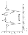
- FIG. 2 shows the hardness curve of a welding point without application of coolant (_._._._._) and with application of coolant (x-x-x-x-x).
- the welding was carried out with fine pearlized UIC 60 rails.
- the method according to DE-PS 21 61 134 was used.
- the preheating time was 2 minutes.
- the aluminothermic reaction mixture was mixed with alloy additives in such a quantity and quantity that the hardness of the intermediate casting area corresponded to that of the finely pearlized rail in the initial state. Compressed air was applied to the rail ends in the immediate vicinity of the mold halves immediately after the aluminothermally produced steel melt had been poured in and was maintained for 4 minutes.
- this is achieved in that after the solidification of the aluminothermally produced steel and the shearing off of the protruding weld metal and the casting mold halves, the cooling on the surface of the rail head, including the intermediate casting area, is continued, while the rail web and the rail foot are not cooled in the intermediate casting area.
- Compressed air is preferably used as the coolant.
- an aluminothermic mixture with less addition of hardness-increasing elements can be used, since the application of coolant to the intermediate casting area and the rapid cooling it brings about result in hardening.
- a softer, more ductile steel is then desirably present, since there was no cooling at these points. This is a very desirable and particularly advantageous result, since the rail foot, which is subjected to bending stress due to the wheel load, and also the rail web can better withstand the dynamic stress in the track.
Landscapes
- Engineering & Computer Science (AREA)
- Mechanical Engineering (AREA)
- Architecture (AREA)
- Civil Engineering (AREA)
- Structural Engineering (AREA)
- Butt Welding And Welding Of Specific Article (AREA)
- Heat Treatment Of Articles (AREA)
- Machines For Laying And Maintaining Railways (AREA)
- Rear-View Mirror Devices That Are Mounted On The Exterior Of The Vehicle (AREA)
- Joining Of Building Structures In Genera (AREA)
Claims (2)
- Procédé pour le soudage par coulée intermédiaire de rails traités par recuit de microperlitisation, par versement d'acier obtenu par aluminothermie dans un moule entourant les deux extrémités des rails et refroidissement des deux extrémités des rails contiguës au moule par un agent réfrigérant, caractérisé en ce qu'après la solidification de l'acier obtenu par aluminothermie et le cisaillement du métal de soudage qui dépasse et des moitiés du moule, le refroidissement se poursuit à la surface du champignon de rail avec intégration de la zone de la coulée intermédiaire, tandis que l'âme et le patin du rail ne sont, dans la zone de coulée intermédiaire, pas refroidis.
- Procédé selon la revendication 1, caractérisé en ce que l'agent réfrigérant est de l'air comprimé.
Priority Applications (1)
| Application Number | Priority Date | Filing Date | Title |
|---|---|---|---|
| AT91102086T ATE96481T1 (de) | 1990-02-27 | 1991-02-14 | Verfahren zur zwischengussschweissung feinperlitisierter schienen. |
Applications Claiming Priority (2)
| Application Number | Priority Date | Filing Date | Title |
|---|---|---|---|
| DE4006071A DE4006071A1 (de) | 1990-02-27 | 1990-02-27 | Verfahren zur zwischengussschweissung feinperlitisierter schienen |
| DE4006071 | 1990-02-27 |
Publications (2)
| Publication Number | Publication Date |
|---|---|
| EP0444480A1 EP0444480A1 (fr) | 1991-09-04 |
| EP0444480B1 true EP0444480B1 (fr) | 1993-10-27 |
Family
ID=6401019
Family Applications (1)
| Application Number | Title | Priority Date | Filing Date |
|---|---|---|---|
| EP91102086A Expired - Lifetime EP0444480B1 (fr) | 1990-02-27 | 1991-02-14 | Procédé pour le soudage par coulée intermédiaire de rails recuits de microperlitisation |
Country Status (6)
| Country | Link |
|---|---|
| US (1) | US5078200A (fr) |
| EP (1) | EP0444480B1 (fr) |
| AT (1) | ATE96481T1 (fr) |
| AU (1) | AU636958B2 (fr) |
| DE (2) | DE4006071A1 (fr) |
| ES (1) | ES2046807T3 (fr) |
Families Citing this family (14)
| Publication number | Priority date | Publication date | Assignee | Title |
|---|---|---|---|---|
| US5419484A (en) * | 1993-04-19 | 1995-05-30 | Radulescu; Stefam R. | Apparatus and process for aluminothermic welding |
| DE4319165C1 (de) * | 1993-06-09 | 1994-08-18 | Elektro Thermit Gmbh | Verfahren zur Zwischengußschweißung feinperlitisierter Schienen |
| DE4319416C1 (de) * | 1993-06-11 | 1994-09-29 | Elektro Thermit Gmbh | Verfahren zum Hochrichten von in der Fahrfläche tiefliegenden Schienenverbindungsschweißungen im Gleis von Eisenbahnen |
| RU2119854C1 (ru) * | 1997-11-25 | 1998-10-10 | Карабанов Владимир Иосифович | Способ алюминотермитной сварки рельсов |
| RU2124424C1 (ru) * | 1998-03-05 | 1999-01-10 | Карабанов Владимир Иосифович | Способ ремонта рельсов |
| RU2191099C2 (ru) * | 1999-07-14 | 2002-10-20 | Открытое акционерное общество "АВТОВАЗ" | Способ дугоконтактной приварки крепежных деталей |
| CA2631923C (fr) * | 2007-05-21 | 2015-07-07 | Truth Hardware Corporation | Mecanisme de verrouillage multipoint |
| CA2681067C (fr) * | 2008-10-03 | 2015-04-14 | Truth Hardware Corporation | Serrure a mortaiser multipoint de porte coulissante avec verrous |
| CA2708912C (fr) * | 2009-06-30 | 2013-02-19 | Truth Hardware Corporation | Mecanisme de verrrouilage a mortaise a points multiples pour porte battante |
| CN105317290B (zh) | 2014-06-20 | 2019-04-19 | 真理五金制品公司 | 锁组件、滑动门组件以及锁致动器组件 |
| NO343484B1 (no) * | 2016-10-28 | 2019-03-25 | Snapwelder As | Fremgangsmåte og konstruksjon til å sammenføye to legemer, samt emne for bruk derved |
| FR3072041B1 (fr) * | 2017-10-09 | 2019-11-29 | Railtech International | Ensemble de moulage pour la soudure aluminothermique de rails et procede de soudure aluminothermique de rails |
| DE102018006415A1 (de) | 2018-08-15 | 2020-02-20 | Goldschmidt Thermit Gmbh | Verfahren zum Abdichten einer Gießform für aluminothermische Schienenschweißungen |
| CN111331041B (zh) * | 2020-03-09 | 2021-06-01 | 燕山大学 | 一种分合式仿形电磁感应加热装置 |
Family Cites Families (12)
| Publication number | Priority date | Publication date | Assignee | Title |
|---|---|---|---|---|
| DE572591C (de) * | 1933-03-18 | Aluminothermische Und Elek Sch | Selbstdichtende Sandform fuer aluminothermische Schienenschweissungen | |
| US2150045A (en) * | 1935-01-05 | 1939-03-07 | Ahlert Wilhelm | Process of welding metals |
| FR816818A (fr) * | 1936-04-22 | 1937-08-18 | Perfectionnement aux traitements thermiques des soudures des rails | |
| FR817911A (fr) * | 1936-05-18 | 1937-09-14 | Laminoirs Hauts Fourneaux Forg | Procédé et dispositif pour souder des rails traités thermiquement |
| DE1201156B (de) * | 1963-10-08 | 1965-09-16 | Elektro Thermit Gmbh | Giessform fuer die aluminothermische Schienen-schweissung |
| FR2123862A5 (en) * | 1971-02-03 | 1972-09-15 | Boutet Camille | Aluminothermic welding - of railway rails |
| DE2208692C3 (de) * | 1972-02-24 | 1974-12-12 | Elektro-Thermit Gmbh, 4300 Essen | Verfahren zur Herstellung aluminothermischerSchienenverbindungssch weißungen |
| US3942579A (en) * | 1973-01-29 | 1976-03-09 | Elektro-Thermit Gmbh. | Process for the aluminothermic welding of rails |
| FR2266570A1 (en) * | 1974-04-03 | 1975-10-31 | Boutet Camille | Aluminothermic welding of railway rails - by spraying coolant onto rails immediately after welding |
| DE2825139C2 (de) * | 1978-06-08 | 1986-10-30 | Elektro-Thermit Gmbh, 4300 Essen | Verfahren zur Durchführung aluminothermischer Schienenverbindungsschweißungen sowie mehrteilige Gießform zur Durchführung des Verfahrens |
| DE2837986C2 (de) * | 1978-08-31 | 1984-04-12 | Elektro-Thermit Gmbh, 4300 Essen | Gießform zur aluminothermischen Schienenverbindungsschweißung |
| AT383072B (de) * | 1985-07-18 | 1987-05-11 | Voest Alpine Ag | Verfahren zur verbindung von aus austenitischem manganhartstahlguss bestehenden herzstuecken mit aus kohlenstoffstahl bestehenden schienen |
-
1990
- 1990-02-27 DE DE4006071A patent/DE4006071A1/de not_active Withdrawn
-
1991
- 1991-02-06 US US07/651,584 patent/US5078200A/en not_active Expired - Fee Related
- 1991-02-14 ES ES199191102086T patent/ES2046807T3/es not_active Expired - Lifetime
- 1991-02-14 EP EP91102086A patent/EP0444480B1/fr not_active Expired - Lifetime
- 1991-02-14 DE DE91102086T patent/DE59100512D1/de not_active Expired - Fee Related
- 1991-02-14 AT AT91102086T patent/ATE96481T1/de active
- 1991-02-26 AU AU71905/91A patent/AU636958B2/en not_active Ceased
Also Published As
| Publication number | Publication date |
|---|---|
| US5078200A (en) | 1992-01-07 |
| AU7190591A (en) | 1991-08-29 |
| DE59100512D1 (de) | 1993-12-02 |
| AU636958B2 (en) | 1993-05-13 |
| ES2046807T3 (es) | 1994-02-01 |
| ATE96481T1 (de) | 1993-11-15 |
| EP0444480A1 (fr) | 1991-09-04 |
| DE4006071A1 (de) | 1991-08-29 |
Similar Documents
| Publication | Publication Date | Title |
|---|---|---|
| DE69523149T2 (de) | Perlitschiene mit hoher abriebfestigkeit und verfahren zu deren herstellung | |
| EP0444480B1 (fr) | Procédé pour le soudage par coulée intermédiaire de rails recuits de microperlitisation | |
| DE69429685T2 (de) | Verfahren zum Herstellen hochfester bainitischer Stahlschienen mit verbesserter Beständigkeit gegen Ermüdungsschäden durch Rollkontakt | |
| DE69427189T3 (de) | Hochfeste, abriebsresistente schiene mit perlitstruktur und verfahren zu deren herstellung | |
| AT395122B (de) | Verfahren zur verbindung von aus manganhartstahlguss bestehenden weichenteilen bzw. manganstahlschienen mit einer schiene aus kohlenstoffstahl | |
| DE2834282C3 (de) | Verfahren zur Verbindung von aus austenitischen Manganhartstahlguß bestehenden Herzstücken mit aus Kohlenstoffstahl bestehenden Schienen | |
| DE2439338C2 (de) | Verfahren zur Wärmebehandlung von Schienen aus der Walzhitze | |
| DE2919156A1 (de) | Verfahren zur herstellung von hochwertigen schienen mit hoher schweissbarkeit | |
| DE2722631C3 (de) | Verfahren zur Herstellung eines Weichen- oder Kreuzungsteiles sowie nach dem Verfahren hergestellter Weichen- oder Kreuzungsteil | |
| DE2227043A1 (de) | Einteiliger ring aus einstueckigem metall unterschiedlicher zusammensetzung und verfahren zu seiner herstellung | |
| DE2825139A1 (de) | Verfahren zur durchfuehrung aluminothermischer schienenverbindungsschweissungen sowie mehrteilige giessform zur durchfuehrung des verfahrens | |
| DE69409524T2 (de) | Schienen | |
| DE102020100520A1 (de) | LASER-SCHWEIßEN VON STAHL ZU KUGELGRAPHITGUSS | |
| DE3640131C2 (fr) | ||
| DE2651946A1 (de) | Verfahren zum aufbringen eines abriebbestaendigen zusammengesetzten ueberzugs auf einen gegenstand | |
| DE4319165C1 (de) | Verfahren zur Zwischengußschweißung feinperlitisierter Schienen | |
| DE2952079C2 (de) | Verfahren zur Herstellung einer Schweißverbindung | |
| EP0628374B1 (fr) | Méthode de soudage par coulée intermédiaire de rails recuits de microperlitisation | |
| EP0058450A1 (fr) | Alliage à base de fer pour le soudage de pièces de fonte à graphite sphéroidal | |
| DE1964751B2 (de) | Lichtbogen-SchweiBverfahren mit hoher Kerbschlagzähigkeit in der Nahtübergangszone und Elektrode hierfür | |
| WO2009043068A1 (fr) | Pièce intermédiaire pour assembler des corps façonnés en acier au manganèse avec de l'acier au carbone, et procédé pour assembler des pièces moulées en acier austénitique au manganèse avec des rails standard | |
| EP1392929B2 (fr) | Coeur de croisement pour aiguillages et son procede de realisation | |
| WO2019166571A1 (fr) | Tête de lance de soufflage à protection contre l'usure des bords des ouvertures de sortie de buses | |
| CH681603A5 (fr) | ||
| DE631389C (de) | Schweissen von Eisenbahn- oder Strassenbahnschienen o. dgl. |
Legal Events
| Date | Code | Title | Description |
|---|---|---|---|
| PUAI | Public reference made under article 153(3) epc to a published international application that has entered the european phase |
Free format text: ORIGINAL CODE: 0009012 |
|
| 17P | Request for examination filed |
Effective date: 19910222 |
|
| AK | Designated contracting states |
Kind code of ref document: A1 Designated state(s): AT BE CH DE ES FR GB IT LI NL SE |
|
| 17Q | First examination report despatched |
Effective date: 19920821 |
|
| ITF | It: translation for a ep patent filed | ||
| GRAA | (expected) grant |
Free format text: ORIGINAL CODE: 0009210 |
|
| AK | Designated contracting states |
Kind code of ref document: B1 Designated state(s): AT BE CH DE ES FR GB IT LI NL SE |
|
| REF | Corresponds to: |
Ref document number: 96481 Country of ref document: AT Date of ref document: 19931115 Kind code of ref document: T |
|
| REF | Corresponds to: |
Ref document number: 59100512 Country of ref document: DE Date of ref document: 19931202 |
|
| ET | Fr: translation filed | ||
| GBT | Gb: translation of ep patent filed (gb section 77(6)(a)/1977) |
Effective date: 19931111 |
|
| REG | Reference to a national code |
Ref country code: ES Ref legal event code: FG2A Ref document number: 2046807 Country of ref document: ES Kind code of ref document: T3 |
|
| PLBE | No opposition filed within time limit |
Free format text: ORIGINAL CODE: 0009261 |
|
| STAA | Information on the status of an ep patent application or granted ep patent |
Free format text: STATUS: NO OPPOSITION FILED WITHIN TIME LIMIT |
|
| 26N | No opposition filed | ||
| EAL | Se: european patent in force in sweden |
Ref document number: 91102086.5 |
|
| PGFP | Annual fee paid to national office [announced via postgrant information from national office to epo] |
Ref country code: NL Payment date: 19970227 Year of fee payment: 7 |
|
| PGFP | Annual fee paid to national office [announced via postgrant information from national office to epo] |
Ref country code: BE Payment date: 19970410 Year of fee payment: 7 |
|
| PGFP | Annual fee paid to national office [announced via postgrant information from national office to epo] |
Ref country code: ES Payment date: 19980226 Year of fee payment: 8 |
|
| PG25 | Lapsed in a contracting state [announced via postgrant information from national office to epo] |
Ref country code: BE Free format text: LAPSE BECAUSE OF NON-PAYMENT OF DUE FEES Effective date: 19980228 |
|
| BERE | Be: lapsed |
Owner name: ELEKTRO-THERMIT G.M.B.H. Effective date: 19980228 |
|
| PG25 | Lapsed in a contracting state [announced via postgrant information from national office to epo] |
Ref country code: NL Free format text: LAPSE BECAUSE OF NON-PAYMENT OF DUE FEES Effective date: 19980901 |
|
| NLV4 | Nl: lapsed or anulled due to non-payment of the annual fee |
Effective date: 19980901 |
|
| PG25 | Lapsed in a contracting state [announced via postgrant information from national office to epo] |
Ref country code: ES Free format text: LAPSE BECAUSE OF NON-PAYMENT OF DUE FEES Effective date: 19990215 |
|
| PGFP | Annual fee paid to national office [announced via postgrant information from national office to epo] |
Ref country code: DE Payment date: 19991231 Year of fee payment: 10 |
|
| PGFP | Annual fee paid to national office [announced via postgrant information from national office to epo] |
Ref country code: SE Payment date: 20000207 Year of fee payment: 10 |
|
| PGFP | Annual fee paid to national office [announced via postgrant information from national office to epo] |
Ref country code: FR Payment date: 20000210 Year of fee payment: 10 |
|
| PGFP | Annual fee paid to national office [announced via postgrant information from national office to epo] |
Ref country code: AT Payment date: 20000211 Year of fee payment: 10 |
|
| PGFP | Annual fee paid to national office [announced via postgrant information from national office to epo] |
Ref country code: CH Payment date: 20000214 Year of fee payment: 10 |
|
| PG25 | Lapsed in a contracting state [announced via postgrant information from national office to epo] |
Ref country code: AT Free format text: LAPSE BECAUSE OF NON-PAYMENT OF DUE FEES Effective date: 20010214 |
|
| PG25 | Lapsed in a contracting state [announced via postgrant information from national office to epo] |
Ref country code: SE Free format text: LAPSE BECAUSE OF NON-PAYMENT OF DUE FEES Effective date: 20010215 |
|
| PG25 | Lapsed in a contracting state [announced via postgrant information from national office to epo] |
Ref country code: LI Free format text: LAPSE BECAUSE OF NON-PAYMENT OF DUE FEES Effective date: 20010228 Ref country code: CH Free format text: LAPSE BECAUSE OF NON-PAYMENT OF DUE FEES Effective date: 20010228 |
|
| REG | Reference to a national code |
Ref country code: ES Ref legal event code: FD2A Effective date: 20010503 |
|
| REG | Reference to a national code |
Ref country code: CH Ref legal event code: PL |
|
| EUG | Se: european patent has lapsed |
Ref document number: 91102086.5 |
|
| PG25 | Lapsed in a contracting state [announced via postgrant information from national office to epo] |
Ref country code: FR Free format text: LAPSE BECAUSE OF NON-PAYMENT OF DUE FEES Effective date: 20011031 |
|
| REG | Reference to a national code |
Ref country code: FR Ref legal event code: ST |
|
| PG25 | Lapsed in a contracting state [announced via postgrant information from national office to epo] |
Ref country code: DE Free format text: LAPSE BECAUSE OF NON-PAYMENT OF DUE FEES Effective date: 20011201 |
|
| REG | Reference to a national code |
Ref country code: GB Ref legal event code: IF02 |
|
| PGFP | Annual fee paid to national office [announced via postgrant information from national office to epo] |
Ref country code: GB Payment date: 20020213 Year of fee payment: 12 |
|
| PG25 | Lapsed in a contracting state [announced via postgrant information from national office to epo] |
Ref country code: GB Free format text: LAPSE BECAUSE OF NON-PAYMENT OF DUE FEES Effective date: 20030214 |
|
| GBPC | Gb: european patent ceased through non-payment of renewal fee | ||
| PG25 | Lapsed in a contracting state [announced via postgrant information from national office to epo] |
Ref country code: IT Free format text: LAPSE BECAUSE OF NON-PAYMENT OF DUE FEES Effective date: 20050214 |