EP0444609A2 - Integriertes geräumiges Gehäuse für eine funkenerosive Vorrichtung - Google Patents
Integriertes geräumiges Gehäuse für eine funkenerosive Vorrichtung Download PDFInfo
- Publication number
- EP0444609A2 EP0444609A2 EP91102821A EP91102821A EP0444609A2 EP 0444609 A2 EP0444609 A2 EP 0444609A2 EP 91102821 A EP91102821 A EP 91102821A EP 91102821 A EP91102821 A EP 91102821A EP 0444609 A2 EP0444609 A2 EP 0444609A2
- Authority
- EP
- European Patent Office
- Prior art keywords
- electrode
- circuit means
- isolation diodes
- housing
- power
- Prior art date
- Legal status (The legal status is an assumption and is not a legal conclusion. Google has not performed a legal analysis and makes no representation as to the accuracy of the status listed.)
- Withdrawn
Links
Images
Classifications
-
- B—PERFORMING OPERATIONS; TRANSPORTING
- B23—MACHINE TOOLS; METAL-WORKING NOT OTHERWISE PROVIDED FOR
- B23H—WORKING OF METAL BY THE ACTION OF A HIGH CONCENTRATION OF ELECTRIC CURRENT ON A WORKPIECE USING AN ELECTRODE WHICH TAKES THE PLACE OF A TOOL; SUCH WORKING COMBINED WITH OTHER FORMS OF WORKING OF METAL
- B23H1/00—Electrical discharge machining, i.e. removing metal with a series of rapidly recurring electrical discharges between an electrode and a workpiece in the presence of a fluid dielectric
-
- B—PERFORMING OPERATIONS; TRANSPORTING
- B23—MACHINE TOOLS; METAL-WORKING NOT OTHERWISE PROVIDED FOR
- B23H—WORKING OF METAL BY THE ACTION OF A HIGH CONCENTRATION OF ELECTRIC CURRENT ON A WORKPIECE USING AN ELECTRODE WHICH TAKES THE PLACE OF A TOOL; SUCH WORKING COMBINED WITH OTHER FORMS OF WORKING OF METAL
- B23H7/00—Processes or apparatus applicable to both electrical discharge machining and electrochemical machining
- B23H7/02—Wire-cutting
- B23H7/04—Apparatus for supplying current to working gap; Electric circuits specially adapted therefor
Definitions
- the present invention relates to apparatus used for the electroerosive working of workpieces. More particularly, the invention relates to packaging of electrical componentry in an integrated gapbox in close relation to the working gap for providing the generation of desired machining pulses to the wire and workpiece.
- the gapbox of the present invention is relatively simple in construction, and is simple to install while being effective in operation.
- Electro-erosive working methods are largely based on empirical findings and hypotheses, because there has hitherto been no conclusive physical description of the discharge processes in the work gap.
- a problem is also caused by vibrations formed as a result of electromagnetic, electrostatic, as well as mechanical or hydraulic effects.
- the power modules comprising generators and switching circuitry, used to provide the desired machining pulses to the wire and workpiece.
- the time control of the discharge process takes place by the controlled switching on or off of the generator with the use of a plurality of power switching circuits placed in parallel relation to the wire electrode for generating selectable pulse shapes for the discharge current.
- a clock may provide clock pulses at a predetermined frequency, and this pulse train is used as a time pattern of trigger pulses to be supplied to the switching circuits as from stored instructions. Desired profiles of pulses may be set as well. In this manner, the erosion process may be readily controlled. Examples of such cutting methods and processes may be found in U.S. Patents 3,928,163 and 4,655,888.
- Disturbances of the erosion process may occur, however, in the distribution of the discharge signals along signal-carrying media to the workpiece.
- Transmission line disturbances in the signal-carrying media can create undesirable effects in the machining process. For example, during the transmission of pulses supplied to the wire, inductive effects as well as distributed capacitive effects in the discharge signal leads tend to distort the desired waveform.
- irregular switching of the plurality of switching circuits may cause undesirable machining pulses which result in less accurate machining or even damage to the switching circuitry.
- the switching circuitry and isolation diodes normally are placed in a power control cabinet having their outputs connected to cabling leading from a location distant from the working area and working gap.
- the lead length from the outputs of the isolation diodes to the wire electrode cause a transmission line effect wherein collapsing magnetic fields in the wiring create voltage spikes relative to multiples of the length of wire.
- the p-n junctions of the isolation diodes tend to dissipate energy caused by these transient voltage spikes which reduces the energy applied to the working gap. Accordingly, use of such machining pulse circuitry in known arrangements generates great amounts of heat.
- the componentry is susceptible to performance degradation and frequent breakdowns due to this effect.
- a further object of the present invention is to provide an arrangement for cooling the heat dissipating componentry of power delivering circuitry in the machining apparatus.
- a still further object of the present invention is to provide a cleaner machining pulse with a faster rise and fall time and with less of a tendency to drive the voltage on the wire to undesired voltage levels.
- An additional object of the present invention is to provide a packaging arrangement that saves space and eliminates wiring and plumbing complications of previous designs.
- an integrated gap box for housing electrical componentry in close relation to the work gap defined by the tool electrode and the workpiece.
- the gapbox provides a large conductive area in contact with the electrical componentry for a power delivering path to the wire electrode. In this way, inductive effects and resistivity between the power delivering circuitry and the workpiece is diminished.
- the invention also makes it possible to provide a cooling mechanism with the use of the fluid medium supplied to the working gap by the normal fluid delivery means of the system.
- a threaded bore is formed in the gapbox as an integral part of the fluid delivery means which cools the heat dissipating circuitry housed in the gapbox.
- an apparatus used for the electroerosive working of a conductive workpiece by a machine tool electrode in an electroerosive machining plant having power delivering circuit means including at least one power switching circuit means coupled with the tool electrode via at least one current grating means for protecting the switching circuit means comprises: an electrical housing for said at least one current grating means positioned in close relation to the tool electrode said housing having an electrically conducting portion in contact with said a least one current grating means for providing a power delivering path to the tool electrode.
- a gapbox integrated in an electro-erosion machinetool having a translatable filamentary erosion electrode supplied by power delivering circuit means comprising a plurality of power switching circuit means, each switching circuit means having an output connected to the input of a respective one of a plurality of isolation diodes for protecting the switching circuit means, and spaced first and second electrode guide and fluid delivery means, said first electrode guide and fluid delivery means having a first outlet for discharging fluid in a direction generally along said electrode
- said gapbox comprising: an electrically conductive housing member having an intermediate portion in electrical contact with the outputs of said isolation diodes and an end portion having a surface in electrical contact with said first electrode guide for providing a conductive path for said power delivering circuit means, said housing member having a longitudinal bore defined therein for providing fluid to said fluid delivery means and to transfer heat from said isolation diodes to said fluid.
- the present invention relates to a packaging arrangement in an electroerosive machining apparatus wherein an integrated gapbox for housing electrical componentry is placed in close relation to the working gap and wire.
- the gapbox provides a housing for isolation diodes which comprise a portion of the power supplying circuitry that supplies the desired waveform of pulses to the wire electrode.
- the gapbox provides a relatively large electrically conductive area of relatively short length to reduce the resistivity of the path of the pulses to the wire electrode and to reduce the transmission and inductive losses otherwise present in known cabling arrangements.
- Another important feature of the invention provides a cooling mechanism for the electrical componentry in the gapbox.
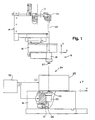
- Fig. 1 shows an electroerosive machining apparatus 8 including an integrated gapbox 10 according to the invention.
- the electroerosive machining apparatus 8 includes a column (not shown) which supports an upper arm 14 and a lower arm 16.
- the upper and lower arms 14, 16 support upper and lower wire guide assemblies 18 and 20.
- the wire guide assemblies support a wire electrode 22 for manipulation of the wire electrode 22 to cut a workpiece 25.
- the wire electrode 22 is positioned in a working zone or area 24 wherein a working gap of approximately .003 inches is provided between the wire electrode 22 and the workpiece 25.
- the wire electrode 22 continuously moves axially through the working zone 24 and is maintained under tension between upper and lower pulleys 26 and 28.
- An upper nozzle portion 27 and a lower nozzle portion 29 attached to the wire guide assemblies 18 and 20, respectively, provide outlet parts through which a dielectric liquid, such as deionized water or oil, flows along the wire electrode 22 and into the working zone 24 and working gap.
- a dielectric liquid such as deionized water or oil
- the pattern of the cut path for the workpiece is determined by a diagrammatically indicated X, Y, U, V, and Z-coordinate control, preferably a numerical control.
- the upper guide assembly 18 and the lower guide assembly 20 are shown with wire 22 in a portion of the overall EDM machine 8 in Figure 1. It will be understood that the upper guide arm 14 travels in the u-v axis by means of a u-v axis assembly 15. The u-v axis assembly permits translation of the upper guide 18 in the u and v horizontal axes.
- the lower guide arm 16 is operatively connected for translation of the lower guide 20 in the x and y horizontal axes.
- the wire 22 is fed horizontally and then vertically along an upper bracket assembly 17. Both the upper bracket assembly 17 and lower guide arm 16 include portions which are not shown in the drawings. In this way, the coordinate axes of the workpiece are driven in relation to the wire electrode 22.
- Power delivering circuitry 32 supplies a stream of pulses to the wire 22 for electrically eroding the workpiece.
- the positive pole (+) of the power delivering circuitry 32 is connected to one connecting point of the workpiece, and in the circuitry of the upper and lower wire guide assemblies 18 and 20.
- the negative pole (-) of the power delivering circuitry 32 is led to the wire electrode 22.
- the polarity can be reversed, as is known in the art, for particular machining operations.
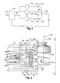
- Fig. 2 therein is shown a simplified electrical schematic of the circuitry that supplies a desired waveform of pulses to the wire electrode 22 according to the present invention.
- three phase power is applied to voltage generating circuitry 34 on a line 36 which provides a direct voltage output at a line 38.
- the voltage generated at line 38 will typically be 80 volts dc for some applications, however, other voltages could just as easily be used.
- n-switching circuits 40a through 40n are arranged in parallel to provide a clean pulse train from the output line 38 of the voltage generating circuitry 34.
- eight switching circuits are used to generate negative pulses with respect to ground.
- Each output of the switching circuits 40a through 40n are supplied on the lines 43a through 43n to the anode of respective isolation diodes 42a through 42n for circuit protection. It has been found that use of isolation diodes 42a through 42n prevent undesired switching disturbances of the switching circuits which may cause an altered pulse train or even damage the system.
- the switching circuits 40a through 40n as well as the isolation diodes 42a through 42n are placed in a remote electrical cabinet.
- Supply cabling is then provided from the output of the isolation diodes 42a through 42n to the wire electrode 22.
- Such wiring creates secondary inductive effects as well as transmission line losses.
- signal reflections in the switching circuitry and secondary cabling create distortions in the desired machining pulse as well as component failures.
- the componentry dissipates heat due to the transition of relatively high operating currents and voltages.
- the remote cabinet may become overheated and cause damage or failure of the system.
- preventative measures such as reducing the frequency of the pulse train must be taken which adversely effect the speed of the machining operation.
- the gapbox 10 provides a housing for the isolation diodes 42a through 42n positioned closely adjacent to the working gap and wire 22 as well as an electrically conducting surface for the output of the isolation diodes 42a through 42n.
- the gapbox 10 comprises an electrically conductive member 46 having an end portion 48 and an intermediate portion 50.
- An insulative plate 52 fabricated of nonconductive material such as G-10 phenolic is mounted adjacent the intermediate portion 50 and is in communication with an endplate 54 of the lower arm 16.
- Coaxial cables transmit the signal pulses from the outputs of the switching circuits to the gapbox 10 and are placed within the lower arm 16. It will be appreciated that four cables are supplied to the gapbox 10.
- the cables 56, 58 and 60 include terminus assemblies 56t, 58t and 60t to terminate the outer jackets of the cables into the endplate 54 of the gapbox 10 as will be well known to those skilled in the art.
- a pair of screws 63 and 65 are received within openings formed in the conductive member 46, insulative plate 52, and endplate 54 to secure the gapbox 10 to the lower arm 16.
- insulative bushings 67 and 69 preferably fabricated of G-10 phenolic are fitted over the screws 63 and 65.
- the lower wire guide assembly 20 is similarly secured to the gapbox conductive member 46 with the use of positioning screws (not shown).
- Electrically conductive elements 57, 59 and 61 corresponding to the coaxial cables 56, 58 and 60 are in electrical contact with a pair of diode subassemblies 64 and 66.
- the diode subassembly 64 comprises two electrically conductive end portions 68 and 70 which comprise slots 72 and 74 to receive clamping screws (now shown) to mate with respective cable terminating conductive elements 57 and 59.
- Intermediate portions 76 and 78 of the diode subassembly 64 house the isolation diodes 42a, 42b, 42c and 42d, respectively, with the anode of the diodes in contact with the conductive elements 57 and 59 of the signal-carrying cables 56 and 58.
- the cathodes of the isolation diodes 42a-42d are contacted with an electrically conductive center block 80, which is preferably fabricated of copper.
- the center block 80 is formed with an aperture 82 for receiving a screw to electrically connect the center block 80 with the intermediate portion 50 of the gapbox conductive member 46.
- the diode subassembly 66 is constructed and operates in exactly the same manner.
- the end portion 48 of gapbox conductive member 46 is engaged in electrical contact with the lower wire guide assembly 20 to form a contacting surface area 84.
- the gapbox conductive member 46 as well as the lower wire guide assembly 20 are preferably fabricated of stainless steel. Although stainless steel is not characterized by a particularly high conductivity, the large surface area and minimum transmission distance ensures an electrical path with minimized resistance.
- the current carrying path of the wire guide assembly 20 houses and is in electrical contact with a carbide contact 86 which electrically engages the wire electrode 22. It will be appreciated that such an arrangement minimizes any transmission line losses and losses due to reflection of the pulse signals in the switching circuitry inasmuch as the pulse signals appearing at the output of the isolation diodes are carried over a minimized conductive path.
- electrical machining pulses are provided in a predetermined waveform to the conductive end portions 68 and 70 of the diode subassemblies 64 and 66 from the switching circuits 40a through 40n via the coaxial cables 56, 58 and 60. Since the machining pulses have negative polarity in the preferred embodiment, the isolation diodes 42a through 42n electrically conduct the machining pulse signals. These signals appear at the electrically conductive center block 80 and traverse the path provided by the electrically conductive member 46 of the gapbox 10 and the lower wire guide assembly 20. The insulative plate 52 prevents conduction of the high voltage electrical pulses through the lower arm 16. In this way, the machining pulses are provided to the carbide contact 86 and the wire electrode 22 over a conductive path having a large area and minimized length. Of course, this will diminish the resistive loss in the machining pulse signal.
- the lead length in this manner eliminates the transmission line effect cause by collapsing magnetic fields in the leads.
- the normally present transient voltage spikes which tend to cause energy dissipated across the isolation diode junctions are either eliminated or substantially reduced. Accordingly, a greater amount of energy is provided to the working gap and wire electrode 22.
- the operating frequency of pulses supplied to the wire electrode 22 may be greatly increased to increase the cutting speed of the machining apparatus 8.
- the machining pulse width in one application may be reduced from four microseconds, which is the pulse width corresponding to a normal operating frequency, to three microseconds. More importantly, the amplitude of the machining pulses provided to the wire electrode may be increased.
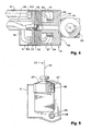
- Figs. 3 and 4 also show a flush conduit 88 which provides a passageway for the dielectric liquid to the wire guide and flushing assembly 20, which discharges the fluid to the working gap 24 (shown in Fig. 1).
- the flush conduit 88 likewise includes a terminus assembly 90 which provides a seal for the conduit 88 to the endplate 54 of the lower arm 16.
- a bore 92 is formed in the insulation plate 52 and gapbox intermediate section 50 and end section 48 and passes through to the wire guide assembly 20 for flushing the working gap and workpiece.
- this arrangement provides a cooling mechanism for the isolation diodes 42a through 42d or other electrical componentry in the gapbox 10.
- the bore 92 is threaded for a greater heat exchange surface area.
- This arrangement minimizes the performance degradation of the electrical componentry by effectively removing heat generated during operation. It has been found that by so cooling the isolation diodes 42a through 42d, the diode junction temperature is cooled to maintain the junction voltage of the diodes at an acceptable operating junction voltage. Accordingly, a higher current tolerance is achieved to operate the system more reliably and efficiently.
- the switching circuits 40a through 40n themselves may be placed within the gapbox 10 with appropriate modification to the system to provide control lines to the switching circuits. By so doing, a cooling mechanism is provided for the switching circuits.
- a cooling mechanism is provided for the switching circuits.
- an elimination of AC waveforms over any significant distance is provided in this arrangement since the switching circuits in the gapbox 10 are supplied with DC voltages.
- fiber optic control may be provided to the gapbox 10 for control of the switching circuitry in the above-mentioned alternative embodiment.
- Such control eliminates any other capacitive, inductive, or electromagnetic effects of the cabling to the wire electrode 22.
- another contemplated location of the gapbox 10 is adjacent the upper wire assembly 18. It will thus be understood that the features preferably utilized together in the advantageous assembly described herein is just one example of the invention.
Landscapes
- Engineering & Computer Science (AREA)
- Mechanical Engineering (AREA)
- Chemical & Material Sciences (AREA)
- Chemical Kinetics & Catalysis (AREA)
- Electrochemistry (AREA)
- Electrical Discharge Machining, Electrochemical Machining, And Combined Machining (AREA)
Applications Claiming Priority (2)
| Application Number | Priority Date | Filing Date | Title |
|---|---|---|---|
| US48517690A | 1990-02-26 | 1990-02-26 | |
| US485176 | 1990-02-26 |
Publications (2)
| Publication Number | Publication Date |
|---|---|
| EP0444609A2 true EP0444609A2 (de) | 1991-09-04 |
| EP0444609A3 EP0444609A3 (en) | 1992-02-26 |
Family
ID=23927187
Family Applications (1)
| Application Number | Title | Priority Date | Filing Date |
|---|---|---|---|
| EP19910102821 Withdrawn EP0444609A3 (en) | 1990-02-26 | 1991-02-26 | Integrated gapbox for electroerosive machining apparatus |
Country Status (4)
| Country | Link |
|---|---|
| EP (1) | EP0444609A3 (de) |
| JP (1) | JPH04226834A (de) |
| KR (1) | KR910021280A (de) |
| CN (1) | CN1055684A (de) |
Families Citing this family (4)
| Publication number | Priority date | Publication date | Assignee | Title |
|---|---|---|---|---|
| JPH1041386A (ja) * | 1996-07-24 | 1998-02-13 | Mitsubishi Electric Corp | 半導体装置の製造方法 |
| JP5031073B2 (ja) * | 2010-07-21 | 2012-09-19 | 株式会社ソディック | ワイヤカット放電加工装置の加工用電源装置 |
| ES2660512T3 (es) * | 2013-08-29 | 2018-03-22 | Agie Charmilles Sa | Máquina de electroerosión por hilo |
| CN108608080B (zh) * | 2016-12-12 | 2020-03-17 | 财团法人金属工业研究发展中心 | 感应式电化学加工装置及其加工方法 |
Family Cites Families (2)
| Publication number | Priority date | Publication date | Assignee | Title |
|---|---|---|---|---|
| DE1515288A1 (de) * | 1964-04-22 | 1969-10-09 | Tsni Lab Elek Tscheskoi Obrabo | Verfahren und Einrichtung zur Funkenerosionsbearbeitung von Werkstuecken |
| US4598189A (en) * | 1984-03-28 | 1986-07-01 | Inoue-Japax Research Incorporated | Automatic wire-threading with a tubular electrode in a TW-E machine |
-
1991
- 1991-02-26 JP JP3114216A patent/JPH04226834A/ja active Pending
- 1991-02-26 EP EP19910102821 patent/EP0444609A3/en not_active Withdrawn
- 1991-02-26 CN CN91101963A patent/CN1055684A/zh active Pending
- 1991-02-26 KR KR1019910003105A patent/KR910021280A/ko not_active Ceased
Also Published As
| Publication number | Publication date |
|---|---|
| JPH04226834A (ja) | 1992-08-17 |
| EP0444609A3 (en) | 1992-02-26 |
| KR910021280A (ko) | 1991-12-20 |
| CN1055684A (zh) | 1991-10-30 |
Similar Documents
| Publication | Publication Date | Title |
|---|---|---|
| EP1932611B1 (de) | Adaptive Spindelanordnung zur Elektroerosionsbearbeitung auf einer CNC-Werkzeugmaschine | |
| US5166489A (en) | Integrated gapbox for electroerosive machining apparatus | |
| CN1065796C (zh) | 放电加工机用电源系统 | |
| EP0698440B1 (de) | Stromversorgungssystem für funkenerosionmaschine | |
| CN1314508C (zh) | 用于对工件进行电腐蚀材料加工的方法和装置 | |
| US3740519A (en) | Electrode for electro-erosion machining electrode | |
| EP0444609A2 (de) | Integriertes geräumiges Gehäuse für eine funkenerosive Vorrichtung | |
| US6140600A (en) | Electric discharge machining apparatus | |
| US4628172A (en) | Gap energizing system for TW electroerosion | |
| US2835784A (en) | Spark machining apparatus | |
| US6552291B1 (en) | Wire electric discharge machine | |
| US4491713A (en) | Power and sensing cable arrangement for electrical discharge machining assembly | |
| JP3731786B2 (ja) | ワイヤ放電加工装置 | |
| EP0137751B1 (de) | Schaltungs-Anordnungen für elektro-erosive Bearbeitung | |
| JP3519150B2 (ja) | 放電加工用回路装置及び放電加工装置 | |
| US4335294A (en) | EDM Method and apparatus having a gap discharge circuit constructed with limited stray capacitances | |
| JP2012024865A (ja) | ワイヤカット放電加工装置の加工用電源装置 | |
| US3558843A (en) | Means for and method of electrical machining with a heated electrode | |
| GB2248032A (en) | An electric discharge machine for simultaneously machining a plurality of workpieces | |
| JPS6094221A (ja) | ワイヤカツト放電加工機におけるワイヤ電極冷却装置 | |
| JP2696388B2 (ja) | 放電加工用電源装置 | |
| KR100322324B1 (ko) | 전기방전가공기용전원시스템 | |
| JPH0459092B2 (de) | ||
| EP0180195A2 (de) | Drahtelektrodenentladungsbearbeitungsgerät | |
| HK1008817B (en) | Power supply system for an electric discharge machine |
Legal Events
| Date | Code | Title | Description |
|---|---|---|---|
| PUAI | Public reference made under article 153(3) epc to a published international application that has entered the european phase |
Free format text: ORIGINAL CODE: 0009012 |
|
| AK | Designated contracting states |
Kind code of ref document: A2 Designated state(s): CH DE FR GB IT LI LU SE |
|
| PUAL | Search report despatched |
Free format text: ORIGINAL CODE: 0009013 |
|
| AK | Designated contracting states |
Kind code of ref document: A3 Designated state(s): CH DE FR GB IT LI LU SE |
|
| 17P | Request for examination filed |
Effective date: 19920803 |
|
| 17Q | First examination report despatched |
Effective date: 19930401 |
|
| STAA | Information on the status of an ep patent application or granted ep patent |
Free format text: STATUS: THE APPLICATION IS DEEMED TO BE WITHDRAWN |
|
| 18D | Application deemed to be withdrawn |
Effective date: 19930812 |