EP0444722A1 - Vorrichtung zum Befestigen entfernbarer Elemente an einer Maschine - Google Patents
Vorrichtung zum Befestigen entfernbarer Elemente an einer Maschine Download PDFInfo
- Publication number
- EP0444722A1 EP0444722A1 EP91200139A EP91200139A EP0444722A1 EP 0444722 A1 EP0444722 A1 EP 0444722A1 EP 91200139 A EP91200139 A EP 91200139A EP 91200139 A EP91200139 A EP 91200139A EP 0444722 A1 EP0444722 A1 EP 0444722A1
- Authority
- EP
- European Patent Office
- Prior art keywords
- arm
- support
- fastening
- hinge point
- opened
- Prior art date
- Legal status (The legal status is an assumption and is not a legal conclusion. Google has not performed a legal analysis and makes no representation as to the accuracy of the status listed.)
- Withdrawn
Links
- 230000033001 locomotion Effects 0.000 claims description 8
- 230000000284 resting effect Effects 0.000 claims 1
- 238000009941 weaving Methods 0.000 description 19
- 239000004744 fabric Substances 0.000 description 6
- 230000003466 anti-cipated effect Effects 0.000 description 3
- 230000007704 transition Effects 0.000 description 3
- 230000005484 gravity Effects 0.000 description 2
- 229910000639 Spring steel Inorganic materials 0.000 description 1
- 230000001154 acute effect Effects 0.000 description 1
- 238000005452 bending Methods 0.000 description 1
- 239000000463 material Substances 0.000 description 1
- 239000004576 sand Substances 0.000 description 1
- 239000004753 textile Substances 0.000 description 1
- 230000009466 transformation Effects 0.000 description 1
Images





Classifications
-
- B—PERFORMING OPERATIONS; TRANSPORTING
- B65—CONVEYING; PACKING; STORING; HANDLING THIN OR FILAMENTARY MATERIAL
- B65H—HANDLING THIN OR FILAMENTARY MATERIAL, e.g. SHEETS, WEBS, CABLES
- B65H19/00—Changing the web roll
- B65H19/10—Changing the web roll in unwinding mechanisms or in connection with unwinding operations
- B65H19/12—Lifting, transporting, or inserting the web roll; Removing empty core
- B65H19/126—Lifting, transporting, or inserting the web roll; Removing empty core with both-ends supporting arrangements
-
- D—TEXTILES; PAPER
- D03—WEAVING
- D03J—AUXILIARY WEAVING APPARATUS; WEAVERS' TOOLS; SHUTTLES
- D03J1/00—Auxiliary apparatus combined with or associated with looms
- D03J1/001—Cloth or warp beam replacement
-
- B—PERFORMING OPERATIONS; TRANSPORTING
- B65—CONVEYING; PACKING; STORING; HANDLING THIN OR FILAMENTARY MATERIAL
- B65H—HANDLING THIN OR FILAMENTARY MATERIAL, e.g. SHEETS, WEBS, CABLES
- B65H2301/00—Handling processes for sheets or webs
- B65H2301/40—Type of handling process
- B65H2301/41—Winding, unwinding
- B65H2301/417—Handling or changing web rolls
- B65H2301/4171—Handling web roll
- B65H2301/4173—Handling web roll by central portion, e.g. gripping central portion
Definitions
- This invention concerns a device for attaching removable elements to a machine.
- the device can be applied to all kinds of machines, but it is meant in the first place for attaching elements in textile machines, such as the attaching of beams, for example warp beams or cloth beams, warp stop motions, harness guides and similar in weaving machines.
- the known devices of the type mentioned above also have the disadvantage that they are not suitable for automatically applying, respectively removing, a beam from its seating.
- the present invention concerns a device for attaching removable elements to machines, such as a warp beam or a cloth beam in weaving machines, which does not have the disadvantages mentioned above, in other words, which is provided of fastenings which can be opened and closed manually or automatically without the use of tools.
- the invention particularly concerns a device whereby the fastenings can be automatically opened and closed when applying and removing the removable element by means of a transporting machine.
- Transporting machines for transporting removable elements, in particular for supplying full warp beams and empty cloth beams, and for removing empty warp beams and full cloth beams from the weaving machines, are generally known. A number of examples are described in the US 3 675 686, WO 88 09405 and DE 3 708 598.
- the invention concerns a device for attaching removable elements to a machine, consisting of two parts which form a detachable seating for a removable element and a fastening which operates in conjunction with these parts, characterized in that this fastening essentially consists of a support fixed to the first of the parts mentioned above; a first arm which is attached to the second part of the parts mentioned above by means of a first hinge point; a second arm which is attached to the first arm by means of a second hinge point, at a certain distance from the first hinge point, and which has a part to which the second arm can clutch behind the support; and means which allow the second arm to move freely along the support mentioned above when the seating is opened.
- the invention has the advantage that, when the seating is opened, the fastening does not hamper the seating in its opening, as a result of which the device is very suitable for attaching removable elements which must be automatically applied to and removed from the machine.
- the device according the invention also makes use of a transporting machine which can operate in conjunction with a fastening and which offers the advantage that an exact positioning of the transporting machine in relation to the fastening is not necessary.
- Fig. 1 shows a schematic representation of a weaving machine 1 and a transporting machine 2 for applying and/or removing an element, in this case a warp beam 3.
- the warp beam 3 hereby has, as is known, fastening parts, in this case shaft ends 4, which are each attached in a device, in this case a bearing 5, on either side in the frame of the weaving machine 1 respectively.
- the above-mentioned transporting machine 2 consists, as is known, of a movable frame 6 which can be moved through the weaving room by means of a controlled drive 7, such as a motor.
- this machine has two arms 8, provided with recesses 9, in which the beam can be applied.
- the arms 8 can be moved both horizontally and vertically by means of drives 10 and 11, which for example consist of drive cylinders.
- the drives 7, 10 and 11 are controlled by means of a control unit 12.
- the weaving machine 1 has, as is shown in figs. 2 and 3, guides 13 over which the warp beam 3 can be rolled into the bearings 5.
- the guides 13 In order to anticipate deviations in the positioning of the transporting machine 2 in relation to the weaving machine 1, on the one hand the guides 13 have been provided with bevels 14 and 15 near their free ends at their inside and upper surface, and on the other hand positioning rings 16 have been applied on the warp beam 3.
- the devices 5 essentially consist of two parts which are to be interconnected by means of a fastening 17, and which form a seating for the above-mentioned element, in this case the warp beam 3, whereby at least one part is movable, such that the seating can be opened and closed.
- the first part consists of a bearing block 18 and the second part of a hingeable bearing lid 19 operating in conjunction with it.
- the fastenings 17 each essentially consist of a support 21 attached to the first part, in this case to the frame 20 of the weaving machine 1; a first arm 22 which is attached to the free end of the second part, in this case the bearing lid 19, by means of a first hinge point 23; a second arm 24 which is attached to the first arm 22 by means of a second hinge point 25, at a distance L1 from the first hinge point 23, as indicated in fig. 6, and which has a part 26 to which the second arm 24 can clutch behind the support 21.
- the first arm 22 also has a stop 27 which operates in conjunction with the frame 20, for example with the upper surface of one of the guides 13.
- the whole has been arranged such that in the situation whereby the second arm 24 clutches behind the support 21, the first hinge point 23 is situated between the support 21 and the second hinge point 25, whereby, as will be further described below, the whole passes a dead centre by the movement of the second hinge point 25, as a result of which the bearing lid 19 in its closed position is clamped to the bearing block 18, and whereby the stop 27 mentioned above keeps the whole in a taut situation, and this in a position whereby the first hinge point 23 is situated just over the dead centre.
- the bearing lid 19 is attached to the frame 20 in a rotatable manner by means of a hinge point 28.
- the stop 27 mentioned above preferably consists of an adjusting bolt which is screwed into a projection 29 on the first arm 22, and which operates in conjunction with the upper surface of the guide 13 concerned.
- the support 21 mentioned above protrudes sideways from the guide 13 concerned. As is shown in fig. 4, the position of the support 21 can be adjusted, as it is applied eccentrically to a rotary cylinder 30 in the frame 20, which can be fixed in a desired angle position by means of a clamping screw 31.
- the above-mentioned part 26 of the second arm 24 has a recess, with an upper surface 32 and a lateral surface 33, whereby the upper surface 32 makes contact with the bottom side of the support 21, and the lateral surface 33 with the side of this support 21.
- the fastening 17 also has means which allow the second arm 24, when the fastening 17 is opened, to be detached from the support 21 such that when the bearing lid 19 is opened, the second arm 24 can move freely along the support 21 mentioned above.
- These means consist of a stop 34, which, as is shown in fig. 4, is formed of an adjusting bolt which makes up part of the second arm 24. The stop 34 is moved such that it makes contact with the bearing lid 19. The function of this stop 34 is further explained in this description.
- the device also has means which allow the first arm 22 to be turned round the first hinge point 23 in either one or the other direction, in order to get the whole across the above-mentioned dead centre in either one of the other direction.
- these means consist of supporting planes 36 and 37 on which a pressure can be exerted.
- the first supporting plane 36 is situated along the side of the first arm 22, near the second hinge point 25, while the second supporting plane 37 is formed by the upper surface of a second projection 38 on the first arm 22.
- the projections 29 and 38 may form a whole, however.
- hinge points 23 and 25 can be formed in various ways. As is shown in fig. 5, the first arm 22 can be turned round a shaft 39 which extends between two flanges 40 of the bearing lid 19. The second hinge point 25 is made such that the second arm 24 hangs sideways next to the guide 13 concerned.
- fastenings 17 are made identical along both sides of the weaving machine.
- Fig. 4 shows the device in the situation whereby the warp beam 3 is located in the device 5, and the fastening 17 is in its locked position.
- the clamping operation of the fastening 17 is shown schematically in figs. 6 to 8.
- the arms 22 and 24 are in a position whereby the upper surface 32 of the part 26 just makes contact with the support 21, without however providing a clamping force.
- the distance L2 between the second hinge point 25 and the support 21 is shorter than the sum of the above-mentioned distance L1 between the two hinge points 23 and 25, and the distance L3 between the hinge point 23 and the support 21.
- the straight line X going through the hinge points 23 and 25 hereby is at an angle M in relation to the straight line Y going through the hinge point 23 and the support 21.
- the second arm 24 is made flexible such that it can be transformed flexibly. In the embodiment shown this is realized because it is made in a U-shape and out of spring steel, whereby the second hinge point 25 and the part 26 are situated near the ends of the legs 41 and 42 of the U-shape.
- the second arm 24 hereby has a length L4 between the second hinge point 25 and the support 21, which is greater than the above-mentioned length L2.
- press elements such as taps 43, which operate in conjunction with the supporting planes 36 and 37 of the fastenings 17, have been applied to the sides of the arms 8.
- the arms 8 are presented to the weaving machine by moving them to the warp beam 3 according to a direction V.
- the arms 8 are hereby located on such a height that the erect parts 44, which bound the recesses 9 at the front ends of the arms 8, can pass underneath the shaft ends 4.
- the taps 43 are hereby located at the height of the respective supporting planes 36.
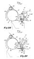
- the further moving of the arms 8 of the transporting machine 2 according to the direction V results in the first arm 22 of each of the fastenings 17 turning further round the first hinge point 23, in particular as shown in fig. 12.
- the second hinge point 25 hereby exerts a force on the second arm 24. Due to the fact that the stop 34 is in contact with the bearing lid 19 and the fact that the stop 34, in relation to the hinge point 25, is situated opposite the hinge point 23, the arms 24 will turn round their hinge points 25 according to arrow A.
- the lateral surfaces 33 of the part 26 are hereby detached from the supports 21.
- the stop 34 hereby causes the fastenings 17 to open, this because of the movement of the arms 8, and is transferred to the arms 24 through the arms 22 and the hinge points 25. It is clear that to this end the above-mentioned means, in particular the stop 34, must be situated such that the arm 24 is turned in a direction opposite to that of the arm 22.
- first hinge point 23 means are provided which ensure that the first arm 22 turns with a certain friction in relation to the bearing lid 19, with the aim to prevent the second arm 24 from turning back by its own weight in the opposite sense of arrow A.
- these means consist for example of clamping elements which are situated between the flanges 40 and the first arm 22, which are formed, for example, of O-rings 45.
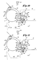
- the arms 8 from the situation in fig. 12 are moved vertically upward until the bottom sides 46 of the recesses 9 are situated at a short distance underneath the shaft ends 4. Then, as shown in fig. 14, the arms 8 are moved back into the transporting machine 2, as indicated by arrow W. As a result, the warp beam 3 is pulled out of the bowl-shaped bearing blocks 18 and subsequently rolled off over the guides 13. As is also shown in fig. 14, the bearing lids 19 hereby tilt open automatically, whereby the stops 35 prevent the arms 24 of the respective fastenings 17 to drop.
- warp beam 3 eventually rests on the bottom sides 46 of the arms 8 when the warp beam 3 rolls off the bevels 15.
- the transporting machine 2 can then remove the empty warp beam 3.
- the bearing lid 19 is held up in its opened position by holding means which in the embodiment shown consist of a clamp 47, for example formed by a U-shaped leaf spring which is fixed to the frame 20.
- holding means can also consist of a permanent magnet or other holding means.
- the arms 8 of the transporting machine 2 are hereby situated at almost the same height as shown in fig. 14.
- the shaft ends 4 hereby each press onto a stop 49 at the respective fastenings 17, fixed to the bearing lid 19, as a result of which the latter is detached from the clamp 47 and drops, while the warp beam 3 rolls into the bearing blocks 18.
- the stop 49 is situated in relation to the bearing lid 19 such that the bearing lid 19 already drops before the tap 43 comes in the environment of the bearing lid 19, and naturally such that this stop 49 does not impede the warp beam 3 when the bearing lid 19 is closed.
- a situation is created as shown in fig. 16.
- the taps 43 come into contact with the supporting planes 37, resulting in the first arms 22 turning round the first hinge points 23, such that the stops 34 of the fastenings 17 are detached from the bearing lids 19.
- the arms 24 turn round their hinge points 25, this under the influence of their own weight, as a result of which the lateral surfaces 33 of their parts 26 make contact with the supports 21, as shown in fig. 17.
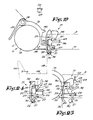
- the stop 34 does not necessarily need to be attached to the second arm 24, but can also make up part of the bearing lid 19, as is shown in fig. 19.
- the distance between the stop 34 and the first hinge point 23 must be greater than the distance between the two hinge points 23 and 25, or in other words, the stop 34 must be situated opposite the first hinge point 23 in relation to the second hinge point 25, such that the second arm 24 is moved in the opposite sense of the first arm 22 due to the movement of the arms 8 of the transporting machine 2.
- Fig. 20 shows a variant whereby the stop 34 consists of a tap which is attached to the bearing lid 19 and which clutches to an opening 50 in the second arm 24.
- the stop 34 is hereby situated in almost the same place as in the embodiment of fig. 19.
- Figs. 21 and 22 show yet another embodiment, whereby the stop 34 consists of an arm which can be rotated round a hinge point 51 in relation to the bearing lid 19, and which is pressed against the upper surface 53 of the second arm 24 by means of a spring 52, and which can operate in conjunction with a projection 54 applied to this arm 24.
- Fig. 21 shows the situation corresponding to the situation in fig. 12. The free end of the stop 34 is hereby pressed into a recess 55 in the above-mentioned upper surface 53.
- the latter has the advantage that the arms 22 and 24 are held in this position and can only be released from this position by an external force, because on the one hand the contact point of the stop 34 is situated in the recess 55, and on the other hand the second hinge point 25 is situated left of the connecting line between the above-mentioned contact point and the first hinge point 23. It is clear from fig. 21 that the stop 35 and the O-rings 45 are now redundant.
- Fig. 22 shows another position corresponding to that of fig. 17.
- the hingeable stop 34 acts on the upper surface 53 of the second arm 24 such that this arm 24 is forced toward the support 21.
- This force which, supplementary to the influence of the weight of the second arm 24, forces the above-mentioned part 26 of this arm 24 toward the support 21, has the advantage that the transition to the situation in fig. 22 is executed faster than if carried out under the influence of gravity alone.
- the stop 34 is situated such that the part 26 moves away from the support 21 faster than the tap 43 of the arm 8 moves. This can be obtained by an appropriate mechanical advantage of lever of the second arm 24, in particular because the distance of the hinge point 25 to the stop 34 is made smaller than the distance to the part 26. This has the advantage that a small move of the tap 43 results in a large move of the part 26, which is necessary in order for this part 26 to pass along the support 21 when the bearing lid 19 is opened.
- the supporting planes 36 and 37 can to this end be formed by means which have a certain flexibility.
- these supporting planes 36 and 37 are formed by the free ends of a profile 56 which is attached to the first arm 22 and which consists for example of a bent leaf spring or similar. Tolerance deviations of the positioning of the transporting machine 2 as the taps 43 make contact with the supporting planes 36 or 37 are anticipated by the bending of the flanges of the profile 56.
- the supporting planes 36 and 37 make up part of the arms 57 and 58 which are attached to the first arm 22 by means of a hinge point 59 and which are supported by the relatively rigid springs 60 and 61.
- the arms 57 and 58 are in their free situation in the position as shown in fig. 24. Tolerance deviations of the positioning of the transporting machine 2 are in this case anticipated by pressing the spring 60 or 61.
- the press elements in other words the taps 43, are made in a flexibly transformable, for example bendable, material such that the tolerance deviations of the positioning of the transporting machine 2 are anticipated by the transformation of these taps 43.
- the taps 43 are supported in a flexible manner by means of springs 62 and 63 according to two directions, in order to anticipate the above-mentioned tolerance deviations.
- the first arm 22 of each of the fastenings 17 may be equipped with a grip 64 for manually opening and fastening this fastening 17.
- the grip 64 When the fastening 17 is opened, the grip 64 is pressed into a clamp 65, which is made analogous to the clamp 47, but is attached to the bearing lid 19 concerned. As a result it is possible to lift the bearing lid 19 by this grip 64.
- one or more springs 66 can be applied between the first arm 22 and the second arm 24, which pull these arms together, in particular pull the second arm 24 to the support 21.
- This has the advantage that the part 26 moves faster to the support 21 during the transition between the positions in figs. 16 and 17. This is particularly advantageous in the case of manual operation. It must be borne in mind that during the transition of the position according to fig. 12 to the position of fig. 14, the arms 22 and 24 remain separated, such that the part 26 can pass along the support 21. In the embodiment shown in fig. 26 this is obtained by the above-mentioned clamp 65. This could also be obtained by creating a sufficiently great friction in the first hinge point 23, for example by means of the above-mentioned O-rings 45. These O-rings, however, are not necessary in the embodiment in fig. 26.
- the device 5 described above can also be applied for attaching a cloth beam, a sand beam, a back rest beam, a warp stop motion, harness guides or other components on the frame of a weaving machine.
- the fastening parts do not necessarily consist of cylindrical shaft ends 4, but may also have another shape.
- the parts 18 and 19 are in that case made in an appropriate form. In fig. 27 an example is shown whereby the shaft ends in have two flat faces 67 and 68.
- the part 26 to which the second arm 24 clutches behind the support 21 is situated between the seating of the removable element and the support 21.
- this part 26 can also be situated at the side of the support 21 which is turned away from the seating of the removable element. This means that the support 21 is situated between the seating and the second arm 24.
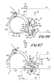
- FIG. 28 shows the fastening 17 in its closed position.
- the part 26 clutches behind the support 21 and the whole is in a taut situation, analogous to the embodiments mentioned above.
- the whole remains in a taut position, as the turning of the first arm 22 is prevented by means of a stop 27 which in this case is applied to the bearing lid 19.
- the whole can be pulled over a dead centre, for example by exerting a pressure on the first arm 22 by means of the tap 43 mentioned above.
- the whole then takes a position as shown in fig. 29, whereby the first arm 22 operates in conjunction with a clamp 65 which is attached to the bearing lid 19.
- the centre of gravity Z of the whole in the example shown is situated in relation to the first hinge point 23 such that the first arm 22 is inclined to turn to the bearing lid 19.
- the clamp 65 is not necessarily provided.
- means which allow the second arm 24 to be detached from the support 21 when the fastening 17 is opened, and which consist of stopping means which for example are formed by the shaft end of the first hinge point 23 and the side 69 of the second arm 24 facing it.
- stopping means which for example are formed by the shaft end of the first hinge point 23 and the side 69 of the second arm 24 facing it.
- these stopping means are situated such that they make contact as the tap 43 is pressed when the fastening 17 is opened, such that the part 26 is removed from the support 21 not only at its upper surface 32 but also at its lateral surface 33.
- the part 26 of the support 21 is removed such that the second arm 24 can move freely along the above-mentioned support 21 when the seating is opened.
- this is obtained because the above-mentioned stopping means are situated between the second hinge point 25 and the above-mentioned part 26, and because the cooperation of the stopping means make the second arm 24 turn round the first hinge point 23, as it were.
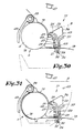
- Figs. 30 and 31 show a variant of the embodiment according to figs. 28 and 29, whereby the above-mentioned stopping means are made such that, as shown in fig. 30, at the moment the fastening 17 is pulled loose, these stopping means do not yet operate in conjunction with each other, and that the second arm 24 still rests against the support 21 with the lateral surface 33.
- the part 26 of the second arm 24 only comes off the support 21 after the bearing lid 19 has already turned over a short distance as the stopping means come into contact with each other.
- the stopping means are hereby situated such that the second arm 24 can move freely along the above-mentioned support 21 when the seating is opened.
- the stopping means are also situated between the second hinge point 25 and the part 26, such that these only come into contact with each other as soon as the bearing lid 19 is already partly opened, as a result of which these stopping means allow the part 26 of the second arm 24 to move freely along the above-mentioned support 21 as the seating is opened further.
- the straight line connecting the lateral surface 33 with the second hinge point 25 and the upper surface 32 form an acute angle.
Landscapes
- Engineering & Computer Science (AREA)
- Textile Engineering (AREA)
- Looms (AREA)
Applications Claiming Priority (4)
| Application Number | Priority Date | Filing Date | Title |
|---|---|---|---|
| BE9000222 | 1990-02-27 | ||
| BE9000222 | 1990-02-27 | ||
| BE9000539 | 1990-05-22 | ||
| BE9000539 | 1990-05-22 |
Publications (1)
| Publication Number | Publication Date |
|---|---|
| EP0444722A1 true EP0444722A1 (de) | 1991-09-04 |
Family
ID=25662515
Family Applications (1)
| Application Number | Title | Priority Date | Filing Date |
|---|---|---|---|
| EP91200139A Withdrawn EP0444722A1 (de) | 1990-02-27 | 1991-01-24 | Vorrichtung zum Befestigen entfernbarer Elemente an einer Maschine |
Country Status (1)
| Country | Link |
|---|---|
| EP (1) | EP0444722A1 (de) |
Cited By (1)
| Publication number | Priority date | Publication date | Assignee | Title |
|---|---|---|---|---|
| CN114192573A (zh) * | 2021-12-31 | 2022-03-18 | 梓兰特线(厦门)科技有限公司 | 一种恒定张力的张力机及异形金属线材生产线 |
Citations (6)
| Publication number | Priority date | Publication date | Assignee | Title |
|---|---|---|---|---|
| US1803286A (en) * | 1929-04-10 | 1931-04-28 | Draper Corp | Cloth roll for looms |
| GB769302A (en) * | 1952-04-17 | 1957-03-06 | Thomas Holt Ltd | Improvements in or relating to beaming machines |
| DE1098457B (de) * | 1954-03-17 | 1961-01-26 | Albert Juergens Fa | Warenaufwickelvorrichtung fuer Webstuehle |
| US3938671A (en) * | 1974-08-13 | 1976-02-17 | Burlington Industries, Inc. | Method and apparatus for handling large fabric rolls for slitting |
| DE2501319A1 (de) * | 1975-01-15 | 1976-07-22 | Salzgitter Peine Stahlwerke | Abrollmaschine fuer stranggut |
| EP0387189A1 (de) * | 1989-03-10 | 1990-09-12 | GebràDer Sulzer Aktiengesellschaft | Webmaschine mit elastischem Riegelelement für das Warenbaumlager |
-
1991
- 1991-01-24 EP EP91200139A patent/EP0444722A1/de not_active Withdrawn
Patent Citations (6)
| Publication number | Priority date | Publication date | Assignee | Title |
|---|---|---|---|---|
| US1803286A (en) * | 1929-04-10 | 1931-04-28 | Draper Corp | Cloth roll for looms |
| GB769302A (en) * | 1952-04-17 | 1957-03-06 | Thomas Holt Ltd | Improvements in or relating to beaming machines |
| DE1098457B (de) * | 1954-03-17 | 1961-01-26 | Albert Juergens Fa | Warenaufwickelvorrichtung fuer Webstuehle |
| US3938671A (en) * | 1974-08-13 | 1976-02-17 | Burlington Industries, Inc. | Method and apparatus for handling large fabric rolls for slitting |
| DE2501319A1 (de) * | 1975-01-15 | 1976-07-22 | Salzgitter Peine Stahlwerke | Abrollmaschine fuer stranggut |
| EP0387189A1 (de) * | 1989-03-10 | 1990-09-12 | GebràDer Sulzer Aktiengesellschaft | Webmaschine mit elastischem Riegelelement für das Warenbaumlager |
Cited By (1)
| Publication number | Priority date | Publication date | Assignee | Title |
|---|---|---|---|---|
| CN114192573A (zh) * | 2021-12-31 | 2022-03-18 | 梓兰特线(厦门)科技有限公司 | 一种恒定张力的张力机及异形金属线材生产线 |
Similar Documents
| Publication | Publication Date | Title |
|---|---|---|
| US6202252B1 (en) | Doctoring apparatus | |
| US5715751A (en) | Printing plate support device and printing plate removably mounting apparatus as well as methods of operating the same | |
| US5657794A (en) | Carriage for changing the harness or heald frame in a loom | |
| JPH04131678U (ja) | ひ道形成装置を備えた織機に用いられる並置綾取り制御装置 | |
| US5307844A (en) | Weaving machine having separable parts with constrained guidance upon assembly and re-assembly | |
| EP0032225B1 (de) | Halterung für Bobinen | |
| EP0444723A1 (de) | Vorrichtung zum Befestigen eines Elementes in einem Lager | |
| DE60300200T2 (de) | Vorrichtung, um das Verpacken von Artikeln zu vereinfachen | |
| EP0409306A1 (de) | Vorrichtung zum Bewegen des Streichbaums in Webmaschinen | |
| BE1007905A3 (nl) | Inrichting voor de inslagselektie op een weefmachine. | |
| US5224518A (en) | Beam seating arrangement in a loom doffer | |
| EP0407334B1 (de) | Webmaschine mit schwenkbarem Kupplungselement für Webschäfte | |
| US4515185A (en) | Apparatus for the constrained actuation of the clamping system of filling-yarn insertion devices in shuttleless weaving machines | |
| EP0309700B1 (de) | Greiferwebmaschine | |
| JP4513646B2 (ja) | 織機における綾取り装置 | |
| US4603713A (en) | Lifting device for a heddle frame | |
| EP0519550A1 (de) | Antriebsvorrichtung einer Leistenfachbildevorrichtung | |
| US4957142A (en) | Tension lever for negative dobby | |
| US5271434A (en) | Control mechanism for the rapier heads of weaving machines | |
| US3951179A (en) | Device for severing a thread in a textile machine | |
| BE1013100A3 (nl) | Poolgaren selectiesysteem voor grijper-axminster weefmachines. | |
| DE69205294T2 (de) | Zugsystem zum Antrieb der Schaftrahmen in negativen Schaftmaschinen. | |
| CH559793A5 (en) | Warp yarn let-off motion control - has a control unit for drive motor acting on positioning of the back rest | |
| US6116293A (en) | Electromagnetic shed forming apparatus for a jacquard machine | |
| RU2102185C1 (ru) | Устройство для регулировки расхода металла при разливке |
Legal Events
| Date | Code | Title | Description |
|---|---|---|---|
| PUAI | Public reference made under article 153(3) epc to a published international application that has entered the european phase |
Free format text: ORIGINAL CODE: 0009012 |
|
| AK | Designated contracting states |
Kind code of ref document: A1 Designated state(s): CH DE FR GB IT LI |
|
| 17P | Request for examination filed |
Effective date: 19911010 |
|
| STAA | Information on the status of an ep patent application or granted ep patent |
Free format text: STATUS: THE APPLICATION IS DEEMED TO BE WITHDRAWN |
|
| 18D | Application deemed to be withdrawn |
Effective date: 19930803 |