EP0444726B1 - Positive device for governing and controlling a rotary dobby in looms - Google Patents
Positive device for governing and controlling a rotary dobby in looms Download PDFInfo
- Publication number
- EP0444726B1 EP0444726B1 EP91200157A EP91200157A EP0444726B1 EP 0444726 B1 EP0444726 B1 EP 0444726B1 EP 91200157 A EP91200157 A EP 91200157A EP 91200157 A EP91200157 A EP 91200157A EP 0444726 B1 EP0444726 B1 EP 0444726B1
- Authority
- EP
- European Patent Office
- Prior art keywords
- levers
- governing
- pair
- controlling
- fact
- Prior art date
- Legal status (The legal status is an assumption and is not a legal conclusion. Google has not performed a legal analysis and makes no representation as to the accuracy of the status listed.)
- Expired - Lifetime
Links
- 230000001737 promoting effect Effects 0.000 claims 2
- 235000000621 Bidens tripartita Nutrition 0.000 claims 1
- 240000004082 Bidens tripartita Species 0.000 claims 1
- 208000006637 fused teeth Diseases 0.000 claims 1
- 230000003993 interaction Effects 0.000 abstract 1
- 230000000903 blocking effect Effects 0.000 description 5
- 230000007246 mechanism Effects 0.000 description 4
- 230000007935 neutral effect Effects 0.000 description 4
- 238000012423 maintenance Methods 0.000 description 2
- 238000006243 chemical reaction Methods 0.000 description 1
- 238000006073 displacement reaction Methods 0.000 description 1
- 230000000694 effects Effects 0.000 description 1
- 239000004744 fabric Substances 0.000 description 1
- 230000000630 rising effect Effects 0.000 description 1
Images

Classifications
-
- D—TEXTILES; PAPER
- D03—WEAVING
- D03C—SHEDDING MECHANISMS; PATTERN CARDS OR CHAINS; PUNCHING OF CARDS; DESIGNING PATTERNS
- D03C1/00—Dobbies
Definitions
- the subject of the present invention is a device for governing and controlling a rotary dobby for actuating heddle frames of looms.
- the governing and control device must, in correspondence with each stop of the main shaft, be capable of making the rotary shaft locked to, or disengaged from, said eccentric which actuates the movement lever mechanisms for the frames, thereby determining for them, in one case, the raising or lowering and, in the other case, the maintenance of the preceding position.
- EP- 0 185 780 Another example of device for controlling a rotary dobby according to the prior art is disclosed into EP- 0 185 780.
- the technical problem therefore arises of creating a device for governing and controlling a rotary dobby for actuating the positioning levers for the frames of the heddles of a loom, the device being equipped with controls and gear, blocking and positive safety means which assure the correct positioning and mutual engagement of the movable parts, both during the rotation with the shaft that determines the variation in the position of the frame and in the neutral or idling position with maintenance of the position adopted by the frame in the preceding revolution.
- Said safety means must, furthermore, contribute to the blocking of the rotation, when each final position corresponding to the half-revolution through 180° is reached.
- Said device which must revolve at high speed, must furthermore be of very small size and mass, must make possible rapid programming, actuating the desired command during the very short stopping time of the main shaft; and it must be easy and economical to assemble and maintain, thus enabling the repair times to be reduced to a minimum.
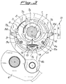
- the device according to this invention is composed of a rotary shaft 1, on which is keyed a disc 2, rotating integrally with the shaft and equipped with two diametrally opposite notches 2a and 2b; on said disc there is concentrically mounted a sleeve 3, on which an eccentric ring 4 can revolve, bounded in its circumferential external surface by a further sleeve 5, which allows it to rotate relative to the oscillating external body 4a of the eccentric 4 connected to an extension 4b pivoted on the actuating bar 6 for the frame of the loom, not illustrated in the Figure.
- a ring 7 is also fixed to the oscillating body 4a by rivets 7c, this ring possessing two notches 7a of substantially trapezoidal shape, diametrally opposite each other, on its internal surface, and two basically semicircular notches 7b on its external surface, diametrally opposite each other and on an axis perpendicular to the axis of the internal notches 7a.
- the device of this invention comprises, furthermore, a first pair of levers 9 and 10, connected to the eccentric 4 at the pivots 9a and 10a respectively, and a second pair of levers 13 and 14, these being attached to the eccentric ring 4 at the respective end pivots 13a and 14a.
- Each lever of said first pair has one of its two ends free, facing inwards and respectively equipped with a radially orientated took 9b and 10b, and also a set of cylindrical gear teeth 9c and 10c respectively, orientated tangentially; said sets of teeth are adapted for engaging each other, in this way forming one single radial tooth 17, having twice the width of the two teeth 9b and 10b, and adapted for engaging with the notch 2a or 2b of the disc 2.
- Said tooth 17 has, moreover, sides suitably shaped for obtaining optimum positioning and engagement with the notch 2a and 2b.
- each lever is, in contrast, equipped with a roller 9d and 10d, and is adapted for receiving a thrust command from a programmer element 13 and for rotating freely on the front annular surface of the oscillating body 4a in the case in which the levers 9 and 10 are engaged with the disc 2, or for engaging with the semicircular notch 7b in the ring 7 under the thrust action from the programmer 13, which itself produces said thrust by small pistons equipped with permanent magnet heads, themselves known, and indicated schematically in the Figure by two arrows A and B, which engage with said rollers 9d and 10d.
- the levers 13 and 14 of said second pair have, in turn, a free end shaped as a set of cylindrical gear teeth 13c and 14c, orientated substantially tangentially and adapted for engaging with each other; said end possesses, in addition, an upper tooth 13b and 14b, adapted for engaging radially into the notch 7a of the ring 7.
- both the pairs of levers 9, 10, 13, 14 have an auxiliary spring or the like 11 and 15, respectively, disposed horizontally; the ends of each spring are attached to the levers of the same pair; said springs exert a restoring action which promotes rotation in the radial centripetal direction of the levers of the first pair and centrifugal radial rotation of the levers of the second pair.
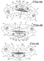
- Fig. 4c there is shown a programming example contrary to that just described.
- the programmer 13 exerts a thrust action on the end 10d of the lever 10, as a consequence of which both the end 10d with a roller of the lever 10 and also the end 9d of the lever 9, caused to rotate by the sets of teeth 9c, 10c, engage into the corresponding notches 7b, thus locking onto the ring 7, in this way overcoming the restoring action of the spring 11 and forcing the two teeth 9b and 10b to disengage from the notch 2a, by rising until they bear against the levers 13 and 14, on which they exert a thrust force which promotes blocking of the oscillating body 4.
Landscapes
- Engineering & Computer Science (AREA)
- Textile Engineering (AREA)
- Looms (AREA)
- Rotational Drive Of Disk (AREA)
- Paper (AREA)
Abstract
Description
- The subject of the present invention is a device for governing and controlling a rotary dobby for actuating heddle frames of looms.
- It is known that the positioning of the frames of the heddles of a loom, determining the weft of the finished fabric, must be programmed in accordance with a predetermined sequence which predicts the raised or lowered position which each frame must adopt at every rotation of the main shaft, to which are firmly attached the oscillating devices which actuate said frames for the purpose of achieving the movement into one of the two desired positions, high or low.
- Because the main shaft is actuated in accordance with an intermittent cycle with a stop at each half-revolution of 180°, the governing and control device must, in correspondence with each stop of the main shaft, be capable of making the rotary shaft locked to, or disengaged from, said eccentric which actuates the movement lever mechanisms for the frames, thereby determining for them, in one case, the raising or lowering and, in the other case, the maintenance of the preceding position.
- Solutions are known in the art which provide the use of eccentrics, coaxially mounted on the rotary shaft, which eccentrics must be brought into a rotationally locked position with an element which converts the rotary motion into an alternating rectilinear motion so as to cause the displacement of the frame, or must be kept idling relative to the shaft but in a fixed position, thus causing the frame to be held in the fixed position.
- In particular, there is known from the Patent Application FR-81 20502, a device which provides an eccentric, rotating with the main shaft, which can be firmly locked to, or kept neutral from, an oscillating element actuating the lever mechanisms governing the movement of the frames, by means of two fixed levers, positioned outside the rotary elements and governed by a programmer for actuating an internal engagement and disengagement mechanism; said device, however, possesses the serious disadvantage that said governing levers and said engagement and disengagement mechanism operate correctly only dependently upon a reaction on an indirect return element composed of a spring which, only if it is perfectly calibrated and in perfect operating conditions, assures the functioning of said control device.
- Another example of device for controlling a rotary dobby according to the prior art is disclosed into EP- 0 185 780.
- The technical problem therefore arises of creating a device for governing and controlling a rotary dobby for actuating the positioning levers for the frames of the heddles of a loom, the device being equipped with controls and gear, blocking and positive safety means which assure the correct positioning and mutual engagement of the movable parts, both during the rotation with the shaft that determines the variation in the position of the frame and in the neutral or idling position with maintenance of the position adopted by the frame in the preceding revolution.
- Said safety means must, furthermore, contribute to the blocking of the rotation, when each final position corresponding to the half-revolution through 180° is reached.
- Said device, which must revolve at high speed, must furthermore be of very small size and mass, must make possible rapid programming, actuating the desired command during the very short stopping time of the main shaft; and it must be easy and economical to assemble and maintain, thus enabling the repair times to be reduced to a minimum.
- Said results are achieved by the present invention, which provides a device for governing and controlling a rotary dobby for the actuation of heddle frames in looms, according to the characterizing part of claim 1
- Further details may be understood from the following description, with reference to the attached drawings, in which there are shown:
- in Figure 1:
- a partial schematic section through the device of this invention in a position with the eccentric engaged;
- in Figure 2:
- a section through the device on the plane of II-II in Figure 1;
- In Figure 3:
- the device of Figure 1 at the end of a rotation through 180° ready to be programmed;
- In Figures 4a/b/c:
- the sequence of release, rotation with levers engaged with the eccentric, blocking and disengagement of the levers, respectively.
- As shown in Figure 1, the device according to this invention is composed of a rotary shaft 1, on which is keyed a
disc 2, rotating integrally with the shaft and equipped with two diametrally opposite notches 2a and 2b; on said disc there is concentrically mounted asleeve 3, on which aneccentric ring 4 can revolve, bounded in its circumferential external surface by a further sleeve 5, which allows it to rotate relative to the oscillatingexternal body 4a of the eccentric 4 connected to an extension 4b pivoted on the actuating bar 6 for the frame of the loom, not illustrated in the Figure. - A ring 7 is also fixed to the oscillating
body 4a byrivets 7c, this ring possessing twonotches 7a of substantially trapezoidal shape, diametrally opposite each other, on its internal surface, and two basically semicircular notches 7b on its external surface, diametrally opposite each other and on an axis perpendicular to the axis of theinternal notches 7a. - The device of this invention comprises, furthermore, a first pair of
levers pivots 9a and 10a respectively, and a second pair oflevers eccentric ring 4 at therespective end pivots cylindrical gear teeth radial tooth 17, having twice the width of the two teeth 9b and 10b, and adapted for engaging with the notch 2a or 2b of thedisc 2. - Said
tooth 17 has, moreover, sides suitably shaped for obtaining optimum positioning and engagement with the notch 2a and 2b. - The other free end of each lever is, in contrast, equipped with a
roller programmer element 13 and for rotating freely on the front annular surface of the oscillatingbody 4a in the case in which thelevers disc 2, or for engaging with the semicircular notch 7b in the ring 7 under the thrust action from theprogrammer 13, which itself produces said thrust by small pistons equipped with permanent magnet heads, themselves known, and indicated schematically in the Figure by two arrows A and B, which engage with saidrollers - The
levers cylindrical gear teeth 13c and 14c, orientated substantially tangentially and adapted for engaging with each other; said end possesses, in addition, an upper tooth 13b and 14b, adapted for engaging radially into thenotch 7a of the ring 7. - In this way, the rotational action imparted to one of the two levers of each pair compels a corresponding rotation in the opposite direction of the other lever.
- In the preferred example of embodiment illustrated in the Figures, both the pairs of
levers programmer 13 is not exerting any thrust action on thefree end 9d of the lever opposite; in this condition, the restoring action of thespring 11 causes thelevers tooth 17 engaged into the notch 2a, and therefore when the shaft 1 starts to rotate it entrains with it thedisc 2 and theeccentric ring 4, with which the levers 9 and 10 and also the levers 13 and 14 integrally move; the latter levers (Fig. 4a), as a result of the inclined shape of the flanks of the teeth 13b and 14b, disengage themselves from thenotch 7a, and move downwards, and exert a direct pressure action on thelevers - With continuing rotation, the teeth 13b and 14b slide in contact with the internal surface of the ring 7, keeping the
levers notch 7a, into which they engage by the effect of the simultaneous stopping of the shaft and the restoring action of the spring 15 (Fig. 4b), in this way releasing thelevers - In Fig. 4c there is shown a programming example contrary to that just described. In this case, after the first rotation through 180°, the
programmer 13 exerts a thrust action on theend 10d of thelever 10, as a consequence of which both theend 10d with a roller of thelever 10 and also theend 9d of thelever 9, caused to rotate by the sets ofteeth spring 11 and forcing the two teeth 9b and 10b to disengage from the notch 2a, by rising until they bear against thelevers body 4. - In these conditions, the rotation of the shaft 1 causes rotation of the
disc 2 only, while the rotation remains neutral with respect to theeccentric ring 4, which keeps its own position, keeping theoscillating body 4a also in its preceding position and consequently also the frame of the loom. - By a succeeding programming, which is intended for causing new engagement of the
levers disc 2, said small piston with magnetic head A or B returns into the at-rest position, and the piston by magnetic attraction will move with it theend auxiliary spring 11. - It is apparent from the foregoing description how the reciprocal action of the two pairs of levers, in addition to causing governing and control of the operation of the heddle frames, constitutes also a positive safety blocking, both in the case of rotation of the eccentric and in the case where this eccentric is in the idling position, thereby guaranteeing maximum accuracy and reliability of the device, which is capable of operating correctly, even in the case of simultaneous breakage of both restoring springs; in the first case on account of the rotation of the
eccentric ring 4 it entrains with it the two pairs of levers, thereby assuring engagement of saidtooth 17 with thedisc 2, whereas in the second case the thrust action of theprogrammer 13, which causes disengagement of thetooth 17 from the notch 2a, with consequent bringing of the oscillatingbody 4a into the neutral condition, is directly promoted by the absence of the restoring action exerted by thespring 11. - Finally, in the case also where the levers are raised and it is necessary to programme the next engagement, the command is positive, being created by the retraction of the magnetic piston, which takes with it the free end of the lever.
Claims (7)
- Device for governing and controlling a rotary dobby for actuating heddle frames of looms, the device comprising a control shaft (1), a disc (2) rotationally locked with said shaft and an eccentric, composed of an eccentric ring (4) keyed onto the shaft (1), with which it can rotate relative to a traversing external body (4a) attached to the actuating bar for the frames, the device comprising a first (9, 10) and a second (13, 14) pair of levers, firmly pivoted on the rotating eccentric ring (4) and adapted for cooperating radially with one another, one free end of said first and said second pair of levers, respectively, being adapted for engaging with said rotating disc (2) and with the traversing body (4a), the other free end (9d, 10d) of the levers of the first pair being, moreover, adapted for receiving any control action from an external programmer device (13), characterized by the fact that the levers (9, 10) of said first pair have one of the the ends formed with a tooth (9b, 10b) orientated substantially radially towards the centre of the eccentric (4) and with a set of cylindrical gear teeth (9c, 10c), orientated substantially tangentially and adapted for making possible reciprocal engagement of the two levers with each other in such a way that the rotation effected by one of the two levers causes an identical rotation of the other lever in the opposite sense, and by the fact that the rotation of the two levers (9, 10) towards the centre of the control shaft (1) by means of said set of gear teeth brings the two teeth (9b, 10b) firmly together to form a single tooth (17) having a width twice that of each of said two teeth.
- Device for governing and controlling a rotary dobby according to Claim 1, characterized by the fact that the programmer incorporates actuating means equipped with permanent magnets, which exert a thrust action or restoring action on the free ends of the levers of the first pair, causing rotation of said levers in a centrifugal or centripetal sense.
- Device for governing and controlling a rotary dobby according to the preceding Claims, characterized by the fact that auxiliary restoring means (11, 15) are applied between the levers of each of said pairs of levers, for the purpose of promoting the rotation in the radial direction of the first and second pairs of levers, respectively, in a centripetal sense and in a centrifugal sense.
- Device for governing and controlling a rotary dobby according to Claim 1, characterized by the fact that the other free end of the levers (9, 10) of said first pair has a sliding element pivoted onto it in the axial direction.
- Device for governing and controlling a rotary dobby according to Claim 1, characterized by the fact that said disc (2) has two notches (2a, 2b), diametrally opposite each other with respect to the centre of rotation of the shaft (1) and adapted for receiving said double tooth (17).
- Device for governing and controlling a rotary dobby according to Claim 1, characterized by the fact that said notches (2a, 2b) and said tooth (17) have flanks and walls respectively shaped to curved or inclined profiles for promoting engagement without play of the tooth in the notch.
- Device for governing and controlling a rotary dobby according to Claim 1, characterized by the fact that said traversing body (4a) has an internal ring (7) equipped with two notches (7a) disposed diametrally opposite each other on the internal surface, and two notches (7b) or the like disposed on its external surface, diametrally opposite each other and on an axis perpendicular to the axis of the internal notches (7a), which are adapted for engaging with the teeth (13b, 14b) of the levers of said second pair, said external notches, in turn, being adapted for engaging with the sliding element (9d, 10d) fitted to the end of the levers (9, 10) of said first pair.
Applications Claiming Priority (2)
| Application Number | Priority Date | Filing Date | Title |
|---|---|---|---|
| IT01926290A IT1237968B (en) | 1990-02-05 | 1990-02-05 | DESMODROMIC DEVICE FOR THE COMMAND AND CONTROL OF A ROTARY DOBBY IN TEXTILE MACHINES |
| IT1926290 | 1990-02-05 |
Publications (2)
| Publication Number | Publication Date |
|---|---|
| EP0444726A1 EP0444726A1 (en) | 1991-09-04 |
| EP0444726B1 true EP0444726B1 (en) | 1996-04-17 |
Family
ID=11156217
Family Applications (1)
| Application Number | Title | Priority Date | Filing Date |
|---|---|---|---|
| EP91200157A Expired - Lifetime EP0444726B1 (en) | 1990-02-05 | 1991-01-26 | Positive device for governing and controlling a rotary dobby in looms |
Country Status (5)
| Country | Link |
|---|---|
| EP (1) | EP0444726B1 (en) |
| AT (1) | ATE136953T1 (en) |
| DE (1) | DE69118742T2 (en) |
| ES (1) | ES2085413T3 (en) |
| IT (1) | IT1237968B (en) |
Families Citing this family (2)
| Publication number | Priority date | Publication date | Assignee | Title |
|---|---|---|---|---|
| IT1251107B (en) * | 1991-07-25 | 1995-05-04 | Costantino Vinciguerra | REFINEMENTS IN A HIGH-SPEED ROTARY DOBBY |
| IT1260291B (en) * | 1992-12-18 | 1996-04-03 | Lucio Burigana | ROTARY DOBBY |
Family Cites Families (6)
| Publication number | Priority date | Publication date | Assignee | Title |
|---|---|---|---|---|
| EP0050160A1 (en) * | 1980-10-10 | 1982-04-28 | GebràDer Sulzer Aktiengesellschaft | Coupling system for operating the heald frames in a loom |
| DE3264016D1 (en) * | 1981-06-26 | 1985-07-11 | Textilma Ag | Coupling device, particularly for looms |
| FR2515702A1 (en) * | 1981-10-29 | 1983-05-06 | Staubli Sa Ets | IMPROVEMENTS ON ROTARY TRACKS |
| EP0185780B1 (en) * | 1984-12-18 | 1989-03-01 | Stäubli AG (Stäubli SA) (Stäubli Ltd.) | Rotary dobby |
| DE3528504C2 (en) * | 1985-08-08 | 1993-10-07 | Kaiser Gmbh & Co Kg | Control device of a rotary dobby |
| CH675734A5 (en) * | 1986-03-22 | 1990-10-31 | Kaiser Gmbh & Co Kg | Loom shaft control |
-
1990
- 1990-02-05 IT IT01926290A patent/IT1237968B/en active IP Right Grant
-
1991
- 1991-01-26 ES ES91200157T patent/ES2085413T3/en not_active Expired - Lifetime
- 1991-01-26 DE DE69118742T patent/DE69118742T2/en not_active Expired - Fee Related
- 1991-01-26 EP EP91200157A patent/EP0444726B1/en not_active Expired - Lifetime
- 1991-01-26 AT AT91200157T patent/ATE136953T1/en not_active IP Right Cessation
Also Published As
| Publication number | Publication date |
|---|---|
| IT9019262A0 (en) | 1990-02-05 |
| DE69118742T2 (en) | 1996-11-28 |
| DE69118742D1 (en) | 1996-05-23 |
| IT9019262A1 (en) | 1991-08-05 |
| EP0444726A1 (en) | 1991-09-04 |
| ES2085413T3 (en) | 1996-06-01 |
| IT1237968B (en) | 1993-06-19 |
| ATE136953T1 (en) | 1996-05-15 |
Similar Documents
| Publication | Publication Date | Title |
|---|---|---|
| EP0444726A1 (en) | Positive device for governing and controlling a rotary dobby in looms | |
| KR19980064814A (en) | Rotary dobby and weaving machines with such dobby | |
| JPS59150136A (en) | Synchronous rotary dobby for loom | |
| EP0525862B1 (en) | Improvements in a high-speed rotary dobby | |
| EP0675218A1 (en) | Shedding control method and apparatus for loom | |
| US5479964A (en) | Rotary dobby having connecting rod automatically disengagable from drive shaft | |
| EP0485009B1 (en) | Device for governing and controlling a rotary dobby of looms, having a profiled cam lever and associated cooperating opposition means | |
| US4444225A (en) | Rotating dobbies | |
| US5918645A (en) | Catch configurations for the pivot arms of a rotary dobby | |
| US4730641A (en) | Rotational dobby | |
| JPH0347338B2 (en) | ||
| GB2051299A (en) | Apparatus for coupling and uncoupling of a kinematic mechanism in which a stepwise rotary motion is imparted | |
| US4727910A (en) | Drive connection for a reciprocating a connecting rod from a drive shaft through an eccentric cam | |
| US4614211A (en) | Dobby | |
| JPH0331817B2 (en) | ||
| EP1191137B1 (en) | Coupling for rotationally connecting actuating shafts of weave machines and weaving looms | |
| EP1251194B1 (en) | Improved programming device for rotary dobbies of weaving machines | |
| US4563911A (en) | Programmer control device | |
| EP0086999B1 (en) | Device for synchronizing the shedding device in a loom | |
| JPS5936012B2 (en) | Control device for rotating dobby machine | |
| US4298031A (en) | Shed forming device for looms | |
| US2499679A (en) | Drive for the axial motion of the camshaft on ordinary straight-bar knitting machines | |
| US4422480A (en) | Loom-heddle selector | |
| SU406701A1 (en) | DEVICE FOR LOCKING | |
| SU1447950A1 (en) | Rotary dobby for loom |
Legal Events
| Date | Code | Title | Description |
|---|---|---|---|
| PUAI | Public reference made under article 153(3) epc to a published international application that has entered the european phase |
Free format text: ORIGINAL CODE: 0009012 |
|
| AK | Designated contracting states |
Kind code of ref document: A1 Designated state(s): AT BE CH DE DK ES FR GB GR IT LI LU NL SE |
|
| 17P | Request for examination filed |
Effective date: 19920220 |
|
| RAP1 | Party data changed (applicant data changed or rights of an application transferred) |
Owner name: BREVTEX SA |
|
| 17Q | First examination report despatched |
Effective date: 19941018 |
|
| GRAA | (expected) grant |
Free format text: ORIGINAL CODE: 0009210 |
|
| AK | Designated contracting states |
Kind code of ref document: B1 Designated state(s): AT BE CH DE DK ES FR GB GR IT LI LU NL SE |
|
| PG25 | Lapsed in a contracting state [announced via postgrant information from national office to epo] |
Ref country code: NL Free format text: LAPSE BECAUSE OF FAILURE TO SUBMIT A TRANSLATION OF THE DESCRIPTION OR TO PAY THE FEE WITHIN THE PRESCRIBED TIME-LIMIT Effective date: 19960417 Ref country code: IT Free format text: LAPSE BECAUSE OF FAILURE TO SUBMIT A TRANSLATION OF THE DESCRIPTION OR TO PAY THE FEE WITHIN THE PRE;WARNING: LAPSES OF ITALIAN PATENTS WITH EFFECTIVE DATE BEFORE 2007 MAY HAVE OCCURRED AT ANY TIME BEFORE 2007. THE CORRECT EFFECTIVE DATE MAY BE DIFFERENT FROM THE ONE RECORDED.SCRIBED TIME-LIMIT Effective date: 19960417 Ref country code: AT Effective date: 19960417 Ref country code: GR Free format text: LAPSE BECAUSE OF FAILURE TO SUBMIT A TRANSLATION OF THE DESCRIPTION OR TO PAY THE FEE WITHIN THE PRESCRIBED TIME-LIMIT Effective date: 19960417 Ref country code: DK Effective date: 19960417 |
|
| REF | Corresponds to: |
Ref document number: 136953 Country of ref document: AT Date of ref document: 19960515 Kind code of ref document: T |
|
| REG | Reference to a national code |
Ref country code: CH Ref legal event code: NV Representative=s name: DR. LUSUARDI AG |
|
| REF | Corresponds to: |
Ref document number: 69118742 Country of ref document: DE Date of ref document: 19960523 |
|
| ET | Fr: translation filed | ||
| REG | Reference to a national code |
Ref country code: ES Ref legal event code: FG2A Ref document number: 2085413 Country of ref document: ES Kind code of ref document: T3 |
|
| PG25 | Lapsed in a contracting state [announced via postgrant information from national office to epo] |
Ref country code: SE Effective date: 19960717 |
|
| NLV1 | Nl: lapsed or annulled due to failure to fulfill the requirements of art. 29p and 29m of the patents act | ||
| PG25 | Lapsed in a contracting state [announced via postgrant information from national office to epo] |
Ref country code: GB Effective date: 19970126 |
|
| PG25 | Lapsed in a contracting state [announced via postgrant information from national office to epo] |
Ref country code: ES Free format text: LAPSE BECAUSE OF NON-PAYMENT OF DUE FEES Effective date: 19970127 |
|
| PG25 | Lapsed in a contracting state [announced via postgrant information from national office to epo] |
Ref country code: BE Effective date: 19970131 Ref country code: LU Free format text: LAPSE BECAUSE OF NON-PAYMENT OF DUE FEES Effective date: 19970131 Ref country code: LI Effective date: 19970131 Ref country code: CH Effective date: 19970131 |
|
| PLBE | No opposition filed within time limit |
Free format text: ORIGINAL CODE: 0009261 |
|
| STAA | Information on the status of an ep patent application or granted ep patent |
Free format text: STATUS: NO OPPOSITION FILED WITHIN TIME LIMIT |
|
| 26N | No opposition filed | ||
| BERE | Be: lapsed |
Owner name: S.A. BREVTEX Effective date: 19970131 |
|
| REG | Reference to a national code |
Ref country code: CH Ref legal event code: PL |
|
| GBPC | Gb: european patent ceased through non-payment of renewal fee |
Effective date: 19970126 |
|
| PG25 | Lapsed in a contracting state [announced via postgrant information from national office to epo] |
Ref country code: FR Effective date: 19970930 |
|
| PG25 | Lapsed in a contracting state [announced via postgrant information from national office to epo] |
Ref country code: DE Effective date: 19971001 |
|
| REG | Reference to a national code |
Ref country code: FR Ref legal event code: ST |
|
| REG | Reference to a national code |
Ref country code: ES Ref legal event code: FD2A Effective date: 20020916 |