EP0444737A2 - Device for scanning a radiography - Google Patents
Device for scanning a radiography Download PDFInfo
- Publication number
- EP0444737A2 EP0444737A2 EP91200358A EP91200358A EP0444737A2 EP 0444737 A2 EP0444737 A2 EP 0444737A2 EP 91200358 A EP91200358 A EP 91200358A EP 91200358 A EP91200358 A EP 91200358A EP 0444737 A2 EP0444737 A2 EP 0444737A2
- Authority
- EP
- European Patent Office
- Prior art keywords
- image
- values
- image memory
- pass filter
- signal processor
- Prior art date
- Legal status (The legal status is an assumption and is not a legal conclusion. Google has not performed a legal analysis and makes no representation as to the accuracy of the status listed.)
- Granted
Links
- 238000002601 radiography Methods 0.000 title 1
- 230000006870 function Effects 0.000 claims abstract description 54
- 239000000523 sample Substances 0.000 claims abstract description 17
- 230000000694 effects Effects 0.000 claims description 7
- 238000001914 filtration Methods 0.000 description 21
- 238000000034 method Methods 0.000 description 9
- 238000010586 diagram Methods 0.000 description 3
- 230000035945 sensitivity Effects 0.000 description 3
- 230000001419 dependent effect Effects 0.000 description 2
- 230000006735 deficit Effects 0.000 description 1
- 239000011159 matrix material Substances 0.000 description 1
- 230000003446 memory effect Effects 0.000 description 1
- 230000005855 radiation Effects 0.000 description 1
Images
Classifications
-
- H—ELECTRICITY
- H04—ELECTRIC COMMUNICATION TECHNIQUE
- H04N—PICTORIAL COMMUNICATION, e.g. TELEVISION
- H04N1/00—Scanning, transmission or reproduction of documents or the like, e.g. facsimile transmission; Details thereof
- H04N1/40—Picture signal circuits
- H04N1/409—Edge or detail enhancement; Noise or error suppression
-
- H—ELECTRICITY
- H04—ELECTRIC COMMUNICATION TECHNIQUE
- H04N—PICTORIAL COMMUNICATION, e.g. TELEVISION
- H04N23/00—Cameras or camera modules comprising electronic image sensors; Control thereof
- H04N23/30—Cameras or camera modules comprising electronic image sensors; Control thereof for generating image signals from X-rays
Definitions
- the invention relates to an arrangement for scanning a charge image, which is generated on a previously locally evenly charged photoconductor during an X-ray irradiation depending on its local intensity, by means of a plurality of electrometer probes arranged in a row, which scan the charge pattern of the photoconductor line by line, which successively in Scanning direction is moved perpendicular to the line direction and which deliver an image value corresponding to the discharge at the pixel for each pixel.
- the two-dimensional charge pattern generated on the surface of the photoconductor which essentially corresponds to the spatial distribution of the X-ray intensity, is scanned by an electrometer arrangement.
- electrometer arrangement Several electrometer probes are provided within the electrometer arrangement, which are arranged in alignment in a row.
- a first line of the charge pattern is first scanned.
- the photoconductor is then moved relative to the electrometer probes in a scanning direction perpendicular to the line direction by approximately one line width.
- the second line is then scanned. This process is repeated until the entire charge pattern of the photoconductor has been scanned.
- the electrical signals generated during the scanning by the electrometer probes are amplified and are then available for further signal processing.
- This object is achieved according to the invention in that the image values are fed to an analog / digital converter and the converted values are read into an image memory and in that a signal processor is provided by means of which the image values of respectively adjacent pixels of an image line with a low-pass filter function and the image values in the scanning direction neighboring pixels with a high-pass filter function.
- the image values initially converted into the digital area are read into an image memory. After this All image values are available, the image values of the individual pixels are processed by means of a signal processor.
- the streaking described above always results in a direction perpendicular to the direction of the lines, ie in the scanning direction.
- This streaking in the scanning direction is now eliminated in that the image values of the pixels read into the image memory are processed by means of a signal processor in such a way that adjacent pixels of an image line are processed with a low-pass filter function and the image values in the scanning direction of adjacent pixels with a high-pass filter function.
- This procedure eliminates streaking in the image quite well, since streaking in the scanning direction means nothing other than a “constant component” which arises from differing probe sensitivity or the like and which should be eliminated as far as possible. Exactly this can be achieved by the described filter function, which is carried out in the local area.
- the two filter functions do not leave the useful signal of the image completely unaffected.
- the design of the filters must be adapted to the respective area of application in order to minimize the impairment of important image information.
- the filter functions by means of the signal processor and of a second image memory can be realized by applying a high-pass filter function to the signal values entered in the first image memory by means of the signal processor in the line direction and temporarily storing them in the second image memory by applying a low-pass filter function to these temporarily stored values in the scanning direction and again in the second image memory by means of the signal processor are temporarily stored and in that, after all values have been calculated, the values temporarily stored in the second image memory are subtracted from the values stored in the first image memory.
- the original image values which are initially stored in the first image memory are processed with the aid of the signal processor in such a way that a high-pass filter function is applied to image values of respectively adjacent image points of an image line.
- the image values obtained in this way are temporarily stored in the second image memory.
- the image values of pixels adjacent in the scanning direction are now subjected to a low-pass filter function.
- These values obtained in this way are in turn temporarily stored in the second image memory, the previously temporarily stored values being able to be overwritten.
- the values stored in the second image memory after performing the low-pass filtering are finally subtracted from the original values stored in the first image memory.
- the high-pass filter function is realized by means of a low-pass filter function and vice versa.
- a low-pass filter function is initially used to generate a high-pass filter function can be provided after the execution of which the values thus generated are subtracted from the original values.
- the result is a high-pass filter function.
- two functions are carried out in succession, the new values calculated in the process being temporarily stored. Only after performing both functions are the values calculated in this way subtracted from the original values.
- the filtering can first be carried out in the scanning direction and then in the line direction.
- the values stored in the second image memory are multiplied by a signal factor before the subtraction from the image values stored in the first image memory by a scaling factor which serves to set the strength of the filter effect.
- the degree of filtering described above can be adjusted by means of a scaling factor depending on the intended use or the streakiness of the scanned image. This can advantageously be done in that the image values stored in the second image memory are subjected to a scaling factor prior to subtraction of the values stored in the first image memory, by means of which they can be reduced as desired, whereby an adjustment of the filter effect is possible.
- the size of the scaling factor is selected as a function of the image amplitude represented by the image values so that it is relatively small in strongly exposed image areas.
- the scaling factor can advantageously be dependent on the height of the image values, i.e. the image amplitude.
- the filtering is reduced with increasing image amplitude.
- the size of the scaling factor is selected as a function of the signal curve in the area around an image value so that the scaling factor is selected to be relatively small in the area of strong signal jumps.
- the scaling factor can also be selected as a function of the signal curve. For this purpose, the course of the signal is examined for several pixels lying next to one another. If a signal jump occurs in the pixel area to be calculated, the scaling factor can be selected to be small in this area, so that the signal jump is influenced as little as possible.
- the filter functions are carried out by means of two one-dimensional filter functions.
- the filter functions carried out in the local area per se represent two-dimensional filtering
- the filtering can advantageously be carried out by means of two one-dimensional filter functions, which can be implemented with less effort.
- FIG. 1 An arrangement shown schematically in FIG. 1 has a photoconductor 1, which was charged uniformly before an X-ray exposure in a manner not shown in the figure and which is discharged during an X-ray exposure depending on the intensity of the X-ray radiation. After this process, the surface of the photoconductor has been discharged to different extents, that is to say has a charge pattern.
- This charge pattern is scanned by means of several electrometer probes 2.
- a large number of electrometer probes are provided, which are provided in alignment in a row on a carrier 3 which is only indicated in the figure.
- a line of the charge pattern is first scanned, ie all the signals supplied by the sensors 2 are read out.
- the photoconductor 1 is then controlled by means of a device (not shown in the figures) a control unit 4 is moved relative to the sensors 2 by approximately the width of a scanning line in the scanning direction. This movement thus runs perpendicular to the line direction, which runs parallel to the carrier 3 of the sensors 2.
- a line of the charge pattern located on the photoconductor 1 is again scanned by means of the electrometer probes 2. This process is repeated until the entire charge pattern has been scanned.
- the signals of the sensors 2 read out during the scanning process are optionally amplified and fed to an A / D converter 5.
- the data thus converted into the digital area are read into an image memory 6.
- the image values of all the pixels are stored in the image memory 6. If, for example, one of the sensors 2 now has a sensitivity that differs from the other sensors, the signals supplied by this sensor would be larger or smaller than the signals supplied by the other sensors. As a result, however, this means nothing other than that streaking in the scanning direction, that is to say transversely to the line direction, occurs in an image which can be represented by reading out the signals stored in the image memory 6.
- Such streakiness could e.g. also arise from differing distances between the different probes and the photoconductor 1 or from low-frequency fluctuations (noise) of the probe signals.
- This streaking can now be at least reduced by applying a low-pass filter function to the image values of respectively adjacent pixels of an image line will.
- the image values in the scanning direction of adjacent pixels are acted upon by a high-pass filter function.
- the high-pass filter function is implemented by means of a low-pass filter function and vice versa.
- the high-pass filtering to be carried out between image values in the scanning direction of adjacent pixels can also be implemented in such a way that low-pass filtering is first carried out with the aid of the signal processor 7.
- the image values obtained in this way are first temporarily stored in a second image memory 8. This is followed by low-pass filtering of image values in each case in a bit line of adjacent pixels in such a way that a high-pass filter function is applied to the image values of these pixels.
- the calculated image values are in turn temporarily stored in the second image memory 8.
- the newly calculated image values obtained in this way, which are stored in the second image memory 8 are subtracted from the original image values stored in the first image memory 6 by means of the signal processor 7.
- the new image values obtained from this subtraction represent the filtered image values and are stored in the second image memory 8, from which these can now be found for further processing or for display on a monitor, for example.
- This inherently two-dimensional filtering can be carried out by means of two one-dimensional filterings.
- both filter functions are selected so that they do not influence the image values Sin in the extreme cases or suppress them completely.
- the choice of these filter functions depends on many parameters, such as the photoconductor used, the photosensors, the distance between the sensors and the photoconductors, the desired resolution, etc., and therefore cannot be given in a generally valid manner. 2 shows, however, that a high-pass filter function is applied to adjacent pixels in the line direction and that a low-pass filter function is applied to adjacent pixels in the scanning direction.
- the filter values subtracted from the originally determined image values, which are stored in the first image memory 6 according to FIG. 1, are additionally subjected to a scaling factor G (k) by means of which the degree of filtering can be influenced.
- the scaling factor G (k) can be selected in various ways.
Landscapes
- Engineering & Computer Science (AREA)
- Multimedia (AREA)
- Signal Processing (AREA)
- Image Processing (AREA)
- Apparatus For Radiation Diagnosis (AREA)
- Facsimile Image Signal Circuits (AREA)
- Transforming Light Signals Into Electric Signals (AREA)
- Facsimile Scanning Arrangements (AREA)
- Image Analysis (AREA)
Abstract
Bei einer Anordnung zum Abtasten einer Röntgenaufnahme, während der ein zuvor örtlich gleichmäßig aufgeladener Photoleiter (1) in Abhängigkeit der örtlichen Intensität entladen wird, mittels mehrerer in einer Reihe angeordneter Elektrometersonden, welche das Ladungsmuster des Photoleiters (1) zeilenweise abtasten, der dabei sukzessiv in Abtastrichtungsenkrecht zur Zeilenrichtung bewegt wird, und welche für jeden Bildpunkt eine Entladung an dem Bildpunkt entsprechenden Bildwert liefern, ist zur Beseitigung von Streifenartefakten vorgesehen, daß die Bildwerte einem Analog Digital-Umsetzer (5) zugeführt und die umgesetzten Werte in einem Bildspeicher (6) eingelesen werden und daß ein Signalprozessor (7) vorgesehen ist, mittels dessen die Bildwerte jeweils benachbarter Bildpunkte einer Bildzeile mit einer Tiefpaßfilterfunktion und die Bildwerte in Abtastrichtung benachbarter Bildpunkte mit einer Hochpaßfilterfunktion beaufschlagt werden.
Description
Die Erfindung betrifft eine Anordnung zum Abtasten eines Ladungsbildes, welches auf einem zuvor örtlich gleichmäßig aufgeladenen Photoleiter während einer Röntgenbestrahlung in Abhängigkeit von deren örtlicher Intensität erzeugt wird, mittels mehrerer in einer Reihe angeordneter Elektrometersonden, welche das Ladungsmuster des Photoleiters zeilenweise abtasten, der dabei sukzessive in Abtastrichtung senkrecht zur Zeilenrichtung bewegt wird und welche für jeden Bildpunkt ein der Entladung an dem Bildpunkt entsprechenden Bildwert liefern.The invention relates to an arrangement for scanning a charge image, which is generated on a previously locally evenly charged photoconductor during an X-ray irradiation depending on its local intensity, by means of a plurality of electrometer probes arranged in a row, which scan the charge pattern of the photoconductor line by line, which successively in Scanning direction is moved perpendicular to the line direction and which deliver an image value corresponding to the discharge at the pixel for each pixel.
Eine solche Anordnung ist aus der DE-OS 35 29 108 sowie aus den darin zitierten Literaturstellen bekannt. Das zweidimensionale, auf der Oberfläche des Photoleiters erzeugte Ladungsmuster, das im wesentlichen der räumlichen Verteilung der Röntgenstrahlungsintensität entspricht, wird von einer Elektrometeranordnung abgetastet. Innerhalb der Elektrometeranordnung sind mehrere Elektrometersonden vorgesehen, welche in einer Reihe fluchtend angeordnet sind. Beim Abtasten des Ladungsmusters wird zunächst eine erste Zeile des Ladungsmusters abgetastet. Anschließend wird der Photoleiter relativ zu den Elektrometersonden in einer Abtastrichtung senkrecht zur Zeilenrichtung um etwa eine Zeilenbreite bewegt. Es wird dann die zweite Zeile abgetastet. Dieser Vorgang wiederholt sich bis das gesamte Ladungsmuster des Photoleiters abgetastet ist. Die bei der Abtastung von den Elektrometersonden erzeugten elektrischen Signale werden verstärkt und stehen dann der weiteren Signalverarbeitung zur Verfügung.Such an arrangement is known from DE-OS 35 29 108 and from the references cited therein. The two-dimensional charge pattern generated on the surface of the photoconductor, which essentially corresponds to the spatial distribution of the X-ray intensity, is scanned by an electrometer arrangement. Several electrometer probes are provided within the electrometer arrangement, which are arranged in alignment in a row. When scanning the charge pattern, a first line of the charge pattern is first scanned. The photoconductor is then moved relative to the electrometer probes in a scanning direction perpendicular to the line direction by approximately one line width. The second line is then scanned. This process is repeated until the entire charge pattern of the photoconductor has been scanned. The electrical signals generated during the scanning by the electrometer probes are amplified and are then available for further signal processing.
Bei derartigen Anordnungen ergibt sich das Problem, daß die einzelnen Elektrometersonden nur selten eine identische Empfindlichkeit aufweisen, was dazu führt, daß die einzelnen Sonden Signale verschiedener Stärke liefern. Im Ergebnis entsteht dadurch eine Streifigkeit in dem Bild, das nach vollständiger Abtastung des Ladungsmusters vorliegt. Ähnliche Probleme ergeben sich aufgrund differierender Abstände der Elektrometersonden zu dem Photoleiter im Bereich der verschiedenen Abtastzeilen. Eine exakte Bewegung des Photoleiters relativ zu den Elektrometermetersonden in der Art, daß für alle Abtastzeilen ein absolut identischer Abstand zwischen den Elektrometersonden und der Oberfläche des Photoleiters gegeben ist, ist praktisch, insbesondere in Anbetracht der Göße und des Gewichts eines solchen Photoleiters, kaum möglich. Auch infolge dieser Probleme ergibt sich eine Streifigkeit des aufgenommenen Bildes. Auch durch niederfrequentes Rauschen in den Sonden nachgeschalteten Verstärkern kann eine Streifigkeit im Bild entstehen.The problem with such arrangements is that the individual electrometer probes rarely have identical sensitivity, which leads to the individual probes providing signals of different strengths. The result is streakiness in the image that is present after the charge pattern has been completely scanned. Similar problems arise due to differing distances between the electrometer probes and the photoconductor in the area of the different scanning lines. An exact movement of the photoconductor relative to the electrometer probes in such a way that there is an absolutely identical distance between the electrometer probes and the surface of the photoconductor for all scanning lines is practically impossible, especially in view of the size and weight of such a photoconductor. These problems also result in streakiness in the captured image. Streakiness in the image can also occur due to low-frequency noise in the amplifiers connected downstream.
Es ist Aufgabe der Erfindung, eine Anordnung der eingangs genannten Art anzugeben, bei der die beschriebenen Probleme zumindest verringert sind.It is an object of the invention to provide an arrangement of the type mentioned in the introduction, in which the problems described are at least reduced.
Diese Aufgabe ist erfindungsgemäß dadurch gelöst, daß die Bildwerte einem Analog/Digital-Umsetzer zugeführt und die umgesetzten Werte in einen Bildspeicher eingelesen werden und daß ein Signalprozessor vorgesehen ist, mittels dessen die Bildwerte jeweils benachbarter Bildpunkte einer Bildzeile mit einer Tiefpaßfilterfunktion und die Bildwerte in Abtastrichtung benachbarter Bildpunkte mit einer Hochpaßfilterfunktion beaufschlagt werden.This object is achieved according to the invention in that the image values are fed to an analog / digital converter and the converted values are read into an image memory and in that a signal processor is provided by means of which the image values of respectively adjacent pixels of an image line with a low-pass filter function and the image values in the scanning direction neighboring pixels with a high-pass filter function.
Die zunächst in den digitalen Bereich umgesetzten Bildwerte werden in einen Bildspeicher eingelesen. Nachdem sämtliche Bildwerte vorliegen, wird mittels eines Signalprozessors eine Bearbeitung der Bildwerte der einzelnen Bildpunkte vorgenommen.The image values initially converted into the digital area are read into an image memory. After this All image values are available, the image values of the individual pixels are processed by means of a signal processor.
Die oben beschriebene Streifigkeit ergibt sich immer in einer Richtung senkrecht zur Richtung der Zeilen, also in der Abtastrichtung. Diese Streifigkeit in Abtastrichtung wird nun dadurch beseitigt, daß mittels eines Signalprozessors die in den Bildspreicher eingelesenen Bildwerte der Bildpunkte dahingehend verarbeitet werden, daß jeweils benachbarte Bildpunkte einer Bildzeile mit einer Tiefpaßfilterfunktion und die Bildwerte in Abtastrichtung benachbarter Bildpunkte mit einer Hochpaßfilterfunktion bearbeitet werden. Durch diese Vorgehensweise werden Streifigkeiten in dem Bild recht gut beseitigt, da eine Streifigkeit in Abtastrichtung nichts anderes bedeutet als einen "Gleichanteil" der durch differierende Sondenempfindlichkeit oder ähnliches entsteht und der möglichst beseitigt werden soll. Genau dies kann durch die beschriebene Filterfunktion, welche im Ortsbereich ausgeführt wird, erzielt werden.The streaking described above always results in a direction perpendicular to the direction of the lines, ie in the scanning direction. This streaking in the scanning direction is now eliminated in that the image values of the pixels read into the image memory are processed by means of a signal processor in such a way that adjacent pixels of an image line are processed with a low-pass filter function and the image values in the scanning direction of adjacent pixels with a high-pass filter function. This procedure eliminates streaking in the image quite well, since streaking in the scanning direction means nothing other than a “constant component” which arises from differing probe sensitivity or the like and which should be eliminated as far as possible. Exactly this can be achieved by the described filter function, which is carried out in the local area.
Grundsätzlich lassen die beiden Filterfunktionen auch das Nutzsignal des Bildes nicht völlig unbeeinflußt. Da jedoch bei Röntgenaufnahmen im medizinischen Anwendungsbereich so gut wie keine ausgedehnten feinen Strukturen vorhanden sind, welche exakt und ausschließlich in Zeilen oder Abtastrichtung verlaufen, tritt kaum ein Verlust an relevanter Bildinformation ein. Darüberhinaus sind die Filter in ihrer Auslegung auf den jeweiligen Anwendungsbereich anzupassen, um eine möglichst geringe Beeinträchtigung wichtiger Bildinformationen zu erzielen.Basically, the two filter functions do not leave the useful signal of the image completely unaffected. However, since there are virtually no extensive fine structures in X-ray images in the medical field of application, which run exactly and exclusively in the lines or scanning direction, there is hardly any loss of relevant image information. In addition, the design of the filters must be adapted to the respective area of application in order to minimize the impairment of important image information.
Nach einer Ausgestaltung der Erfindung ist vorgesehen, daß die Filterfunktionen mittels des Signalprozessors und eines zweiten Bildspeichers realisiert werden, indem die in dem ersten Bildspeicher eingegebenen Signalwerte mittels des Signalprozessors in Zeilenrichtung mit einer Hochpaßfilterfunkton beaufschlagt und in dem zweiten Bildspeicher zwischengespeichert werden, indem mittels des Signalprozessors diese zwischengespeicherten Werte in Abtastrichtung mit einer Tiefpaßfilterfunktion beaufschlagt und wiederum in dem zweiten Bildspeicher zwischengespeichert werden und indem nach Berechnung aller Werte die in dem zweiten Bildspeicher zwischengespeicherten Werte von den in dem ersten Bildspeicher abgespeicherten Werten subtrahiert werden.According to one embodiment of the invention it is provided that the filter functions by means of the signal processor and of a second image memory can be realized by applying a high-pass filter function to the signal values entered in the first image memory by means of the signal processor in the line direction and temporarily storing them in the second image memory by applying a low-pass filter function to these temporarily stored values in the scanning direction and again in the second image memory by means of the signal processor are temporarily stored and in that, after all values have been calculated, the values temporarily stored in the second image memory are subtracted from the values stored in the first image memory.
Die zunächst in dem ersten Bildspeicher abgespeicherten ursprünglichen Bildwerte werden mit Hilfe des Signalprozessors in der Weise bearbeitet, daß Bildwerte jeweils benachbarter Bildpunkte einer Bildzeile mit einer Hochpaßfilterfunktion beaufschlagt werden. Die so gewonnenen Bildwerte werden in dem zweiten Bildspeicher zwischengespeichert. Ausgehend von den in dem zweiten Bildspeicher zwischengespeicherten Werte werden nun die Bildwerte von in Abtastrichtung benachbarten Bildpunkten mit einer Tiefpaßfilterfunktion beaufschlagt. Diese so gewonnenen Werte werden wiederum in dem zweiten Bildspeicher zwischengespeichert, wobei die zuvor zwischengespeicherten Werte überschrieben werden können. Die nach Durchführung der Tiefpaßfilterung in dem zweiten Bildspeicher abgespeicherten Werte werden schließlich von den ursprünglichen in dem ersten Bildspeicher abgespeicherten Werte subtrahiert.The original image values which are initially stored in the first image memory are processed with the aid of the signal processor in such a way that a high-pass filter function is applied to image values of respectively adjacent image points of an image line. The image values obtained in this way are temporarily stored in the second image memory. Starting from the values temporarily stored in the second image memory, the image values of pixels adjacent in the scanning direction are now subjected to a low-pass filter function. These values obtained in this way are in turn temporarily stored in the second image memory, the previously temporarily stored values being able to be overwritten. The values stored in the second image memory after performing the low-pass filtering are finally subtracted from the original values stored in the first image memory.
Bei dieser Vorgehensweise wird also die Hochpaßfilterfunktion mittels einer Tiefpaßfilterfunktion realisiert und umgekehrt. Dies ist möglich, da z.B. für die Erzeugung einer Hochpaßfilterfunktion zunächst eine Tiefpaßfilterfunktion vorgesehen werden kann, nach deren Durchführung die so erzeugten Werte von den ursprünglichen Werten subtrahiert werden. Im Ergebnis liegt dann wieder eine Hochpaßfilterfunktion vor. In der erfindungsgemäßen Anordnung werden zwei Funktionen nacheinander durchgeführt, wobei die dabei berechneten neuen Werte zwischengespeichert werden. Erst nach Durchführung beider Funktionen werden die so berechneten Werte von den ursprünglichen Werte subtrahiert.With this procedure, the high-pass filter function is realized by means of a low-pass filter function and vice versa. This is possible because, for example, a low-pass filter function is initially used to generate a high-pass filter function can be provided after the execution of which the values thus generated are subtracted from the original values. The result is a high-pass filter function. In the arrangement according to the invention, two functions are carried out in succession, the new values calculated in the process being temporarily stored. Only after performing both functions are the values calculated in this way subtracted from the original values.
Es ist im Ergebnis gleichwertig, in welcher Reihenfolge die Filterungen vorgenommen werden; es kann also auch , wie nach einer Ausgestaltung vorgesehen ist, zunächst die Filterung in Abtastrichtung und dann diejenige in Zeilenrichtung vorgenommen werden.The result is equivalent in the order in which the filtering is carried out; Thus, as is provided according to one embodiment, the filtering can first be carried out in the scanning direction and then in the line direction.
Der Vorteil dieser Vorgehensweise liegt vor allem darin, daß die Korrektur mit geringem Rechenaufwand erfolgen kann.The main advantage of this procedure is that the correction can be carried out with little computing effort.
Nach einer weiteren Ausgestaltung der Erfindung ist vorgesehen, daß die in dem zweiten Bildspeicher abgespeicherten Werte vor Subtraktion von den in dem ersten Bildspeicher abgespeicherten Bildwerten mittels des Signalprozessors mit einem Skalierungsfaktor multipliziert werden, der der Einstellung der Stärke der Filterwirkung dient.According to a further embodiment of the invention, it is provided that the values stored in the second image memory are multiplied by a signal factor before the subtraction from the image values stored in the first image memory by a scaling factor which serves to set the strength of the filter effect.
Das Maß der oben beschriebenen Filterung kann je nach Einsatzzweck bzw. Streifigkeit des abgetasteten Bildes mittels eines Skalierungsfaktors eingestellt werden. Dies kann vorteilhafterweise dadurch geschehen, daß die in dem zweiten Bildspeicher abgespeicherten Bildwerte vor Subtraktion der in dem ersten Bildspeicher abgespeicherten Werte mit einem Skalierungsfaktor beaufschlagt werden, mittels dessen sie beliebig verkleinert werden können, wodurch eine Einstellung der Filterwirkung möglich ist.The degree of filtering described above can be adjusted by means of a scaling factor depending on the intended use or the streakiness of the scanned image. This can advantageously be done in that the image values stored in the second image memory are subjected to a scaling factor prior to subtraction of the values stored in the first image memory, by means of which they can be reduced as desired, whereby an adjustment of the filter effect is possible.
Nach einer weiteren Ausgestaltung der Erfindung ist vorgesehen, daß die Größe des Skalierungsfaktors in Abhängigkeit der von den Bildwerten repräsentierten Bildamplitude so gewählt wird, daß er in stark belichteten Bildbereichen relativ klein ist.According to a further embodiment of the invention, it is provided that the size of the scaling factor is selected as a function of the image amplitude represented by the image values so that it is relatively small in strongly exposed image areas.
Um insbesondere relevante Bildwerte, welche meist einen relativ großen Signalpegel aufweisen, möglichst wenig negativ durch die Filterung zu beeinflussen, kann der Skalierungsfaktor vorteilhafterweise in Anhängigkeit der Höhe der Bildwerte, d.h. also der Bildamplitude, gewählt werden. Es wird dabei die Filterung mit steigender Bildamplitude verkleinert.In order to influence the relevant image values, which usually have a relatively large signal level, as little as possible negatively through the filtering, the scaling factor can advantageously be dependent on the height of the image values, i.e. the image amplitude. The filtering is reduced with increasing image amplitude.
Nach einer weiteren Ausgestaltung der Erfindung ist vorgesehen, daß die Größe des Skalierungsfaktors in Abhängigkeit des Signalverlaufs im Bereich um einen Bildwert so gewählt wird, daß der Skalierungsfaktor im Bereich starker Signalsprünge relativ klein gewählt wird.According to a further embodiment of the invention, it is provided that the size of the scaling factor is selected as a function of the signal curve in the area around an image value so that the scaling factor is selected to be relatively small in the area of strong signal jumps.
Da insbesondere Signalsprünge durch die Filterung möglichst unbeeinflußt bleiben sollen, kann der Skalierungsfaktor außerdem in Abhängigkeit des Signalverlaufs gewählt werden. Es wird dazu für mehrere nebeneinanderliegende Bildpunkte der Verlauf des Signals untersucht. Tritt in dem zu berechnenden Bildpunktebereich ein Signalsprung auf, so kann in diesem Bereich der Skalierungsfaktor klein gewählt werden, so daß eine möglichst geringe Beeinflussung des Signalsprunges eintritt.Since, in particular, signal jumps should remain as unaffected as possible by the filtering, the scaling factor can also be selected as a function of the signal curve. For this purpose, the course of the signal is examined for several pixels lying next to one another. If a signal jump occurs in the pixel area to be calculated, the scaling factor can be selected to be small in this area, so that the signal jump is influenced as little as possible.
Nach einer weiteren Ausgestaltung der Erfindung ist vorgesehen, daß die Filterfunktionen mittels zweier eindimensionaler Filterfunktionen durchgeführt werden. Die in dem Ortsbereich ausgeführten Filterfunktionen stellen an sich eine zweidimensionale Filterung dar. Um den technischen Aufwand jedoch möglichst gering zu halten, können die Filterungen vorteilhafterweise mittels zweier eindimensionaler Filterfunktion durchgeführt werden, welche mit geringerem Aufwand realisierbar sind.According to a further embodiment of the invention it is provided that the filter functions are carried out by means of two one-dimensional filter functions. The filter functions carried out in the local area per se represent two-dimensional filtering However, to keep the effort as low as possible, the filtering can advantageously be carried out by means of two one-dimensional filter functions, which can be implemented with less effort.
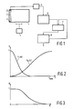
Ein Ausführungsbeispiel der Erfindung wird anhand der Zeichnung näher erläutert. Es zeigen:
- Fig. 1
- Ein Blockschaltbild einer erfindungsgemäßen Anordnung,
- Fig. 2
- ein Diagramm für zwei eindimensionale Filterfunktionen,
- Fig. 3
- ein Diagramm, daß die bildamplitudenabhängige Wahl des Skalierungsfaktors darstellt.
- Fig. 1
- A block diagram of an arrangement according to the invention,
- Fig. 2
- a diagram for two one-dimensional filter functions,
- Fig. 3
- a diagram that represents the image amplitude-dependent choice of the scaling factor.
Eine in Fig. 1 schematisch dargestellte Anordnung weist einen Photoleiter 1 auf, welcher vor einer Röntgenaufnahme in der Figur nicht näher dargestellter Weise gleichmäßig aufgeladen wurde und der während einer Röntgenaufnahme in Abhängigkeit von der Intensität der Röntgenstrahlung entladen wird. Nach diesem Vorgang ist die Oberfläche des Photoleiters örtlich verschieden stark entladen worden, weist also ein Ladungsmuster auf.An arrangement shown schematically in FIG. 1 has a photoconductor 1, which was charged uniformly before an X-ray exposure in a manner not shown in the figure and which is discharged during an X-ray exposure depending on the intensity of the X-ray radiation. After this process, the surface of the photoconductor has been discharged to different extents, that is to say has a charge pattern.
Dieses Ladungsmuster wird mittels mehrerer Elektrometersonden 2 abgetastet. Es ist eine Vielzahl von Elektrometersonden vorgesehen, welcher in einer Reihe fluchtend auf einem in der Figur nur angedeuteten Träger 3 vorgesehen sind. Bei der Abtastung des Photoleiters 1 wird zunächst eine Zeile des Ladungsmusters abgetastet, d.h. es werden alle von den Sensoren 2 gelieferten Signale ausgelesen. Anschließend wird der Photoleiter 1 mittels einer in den Figuren nicht dargestellten Vorrichtung gesteuert durch eine Steuerungseinheit 4 relativ zu den Sensoren 2 um etwa die Breite einer Abtastzeile in Abtastrichtung bewegt. Diese Bewegung verläuft also senkrecht zur Zeilenrichtung, welche parallel zu dem Träger 3 der Sensoren 2 verläuft. Nachdem der Photoleiter relativ zu den Sensoren weiterbewegt worden ist, wird wiederum eine Zeile des auf dem Photoleiter 1 befindlichen Ladungsmusters mittels der Elektrometersonden 2 abgetastet. Dieser Vorgang wiederholt sich bis das gesamte Ladungsmuster abgetastet ist.This charge pattern is scanned by means of several electrometer probes 2. A large number of electrometer probes are provided, which are provided in alignment in a row on a carrier 3 which is only indicated in the figure. When the photoconductor 1 is scanned, a line of the charge pattern is first scanned, ie all the signals supplied by the
Die bei dem Abtastvorgang ausgelesenen Signale der Sensoren 2 werden gegebenenfalls verstärkt und einem A/D-Umsetzer 5 zugeführt. Die so in den digitalen Bereich umgesetzten Daten werden in einen Bildspeicher 6 eingelesen. Nach einem vollständigen Abtastvorgang des Ladungsmusters des Photoleiters 1 sind in dem Bildspeicher 6 die Bildwerte sämtlicher Bildpunkte abgespeichert. Sollte nun beispielsweise einer der Sensoren 2 eine von den übrigen Sensoren differierende Empfindlichkeit aufweisen, so wären die von diesem Sensor gelieferten Signale größer bzw. kleiner als die von den übrigen Sensoren gelieferten Signale. Dies bedeutet im Ergebnis aber nichts anderes, als daß in einem Bild, das durch Auslesen der in dem Bildspeicher 6 gespeicherten Signale darstellbar ist, eine Streifigkeit in Abtastrichtung, also quer zur Zeilenrichtung, auftritt.The signals of the
Eine solche Streifigkeit könnte aber z.B. auch durch differierende Abstände zwischen den verschiedenen Sonden und dem Photoleiter 1 oder durch niederfrequente Schwankungen (Rauschen) der Sondensignale entstehen.Such streakiness could e.g. also arise from differing distances between the different probes and the photoconductor 1 or from low-frequency fluctuations (noise) of the probe signals.
Diese Streifigkeit kann nun dadurch zumindest vermindert werden, daß die Bildwerte jeweils benachbarter Bildpunkte einer Bildzeile mit einer Tiefpaßfilterfunktion beaufschlagt werden. Die Bildwerte in Abtastrichtung benachbarter Bildpunkte werden dagegen mit einer Hochpaßfilterfunktion beaufschlagt. Dabei wird die Hochpaßfilterfunktion mittels einer Tiefpaßfilterfunktion realisiert und umgekehrt. Dabei kann die zwischen Bildwerten in Abtastrichtung benachbarter Bildpunkte vorzunehmende Hochpaß-Filterung auch so realisiert werden, daß mit Hilfe des Signalprozessors 7 zunächst eine Tiefpaß-Filterung durchgeführt wird. Die so gewonnenen Bildwerte werden zunächst in einem zweiten Bildspeicher 8 zwischengespeichert. Anschließend erfolgt eine Tiefpaßfilterung von Bildwerten jeweils in einer Bitzeile benachbarter Bildpunkte in der Weise, daß die Bildwerte dieser Bildpunkte mit einer Hochpaßfilterfunktion beaufschlagt werden. Es kann dabei von den in dem zweiten Bildspeicher 8 abgespeicherten Bildwerten ausgegangen werden. Die berechneten Bildwerte werden wiederum in dem zweiten Bildspeicher 8 zwischengespeichert. Die so gewonnenen neu berechneten Bildwerte, die in dem zweiten Bildspeicher 8 abgespeichert sind, werden mittels des Signalprozessors 7 von den in dem ersten Bildspeicher 6 abgespeicherten ursprünglichen Bildwerten subtrahiert. Die aus dieser Subtraktion gewonnenen neuen Bildwerte stellen die gefilterten Bildwerte dar und werden in dem zweiten Bildspeicher 8 abgespeichert, dem diese nunmehr zur weiteren Verarbeitung bzw. zur Darstellung beispielsweise auf einem Monitor entnehmbar sind.This streaking can now be at least reduced by applying a low-pass filter function to the image values of respectively adjacent pixels of an image line will. In contrast, the image values in the scanning direction of adjacent pixels are acted upon by a high-pass filter function. The high-pass filter function is implemented by means of a low-pass filter function and vice versa. The high-pass filtering to be carried out between image values in the scanning direction of adjacent pixels can also be implemented in such a way that low-pass filtering is first carried out with the aid of the
Die oben beschriebene, im Ortsbereich vorgenommene Filterung läßt sich mathematisch wie folgt darstellen:
Bezeichnet man die vor der Filterung vorliegenden Bildwerte in einer Matrix mit der Bezeichnung S (z,a), wobei mit z Ortsfrequenzen in Zeilenrichtung und a Ortsfrequenzen in Abtastrichtung bezeichnet sind, so lassen sich die gefilterten Bildwerte S'(z,a) in folgender Weise beschreiben:

In dieser Gleichung stellt Fs(z,a) die Filterfunktion dar, und G(k) den Skalierungsfaktor. Die Filterfunktion Fs(z,a) läßt sich dabei wie folgt beschreiben:

Damit soll angedeutet sein, daß in Zeilenrichtung die benachbarten Bildwerte mit einer Hochpaßfilterfunktion und in der Abtastrichtung, die senkrecht zur Zeilenrichtung verläuft, mit einer Tiefpaßfunktion beaufschlagt werden. Diese an sich zweidimensionale Filterung kann mittels zweier eindimensionaler Filterungen vorgenommen werden.The filtering performed in the local area described above can be represented mathematically as follows:
If the image values present before the filtering are designated in a matrix with the designation S (z, a), z being designated as spatial frequencies in the line direction and a as spatial frequencies in the scanning direction the filtered image values S '(z, a) are described in the following way:
In this equation, F s (z, a) represents the filter function and G (k) the scaling factor. The filter function F s (z, a) can be described as follows:
This is intended to indicate that the adjacent image values are acted upon in the line direction with a high-pass filter function and in the scanning direction, which is perpendicular to the line direction, with a low-pass function. This inherently two-dimensional filtering can be carried out by means of two one-dimensional filterings.
In Fig. 2 sind zwei solcher eindimensionale Filterfunktionen exemplarisch dargestellt. In diesem Beispielsfall sind beide Filterfunktionen so gewählt, daß sie die Bildwerte Sin den Extremfällen jeweils gar nicht beeinflussen oder vollständig unterdrücken. Die Wahl dieser Filterfunktionen ist von vielen Parametern abhängig, so z.B. von dem verwendeten Photoleiter, den Photosensoren, dem Abstand zwischen den Sensoren und den Photoleitern, der gewünschten Auflösung etc., und kann deshalb nicht allgemein gültig angegeben werden. Die Darstellung gemäß Fig. 2 zeigt jedoch, daß in Zeilenrichtung benachbarte Bildpunkte mit einer Hochpaßfilterfunktion beaufschlagt werden und daß in Abtastrichtung benachbarte Bildpunkte mit einer Tiefpaßfilterfunktion beaufschlagt werden. Die aus dieser Filterung hervorgegangenen Werte werden von den Ausgangswerten abgezogen, so daß im Endeffekt die genau umgekehrte Filterung eintritt, d.h. in Zeilenrichtung tritt im Ergebnis eine Tiefpaßfilterung und in Abtastrichtung senkrecht zur Zeilenrichtung im Ergebnis eine Hochpaßfilterung ein.Two such one-dimensional filter functions are exemplarily shown in FIG. In this example, both filter functions are selected so that they do not influence the image values Sin in the extreme cases or suppress them completely. The choice of these filter functions depends on many parameters, such as the photoconductor used, the photosensors, the distance between the sensors and the photoconductors, the desired resolution, etc., and therefore cannot be given in a generally valid manner. 2 shows, however, that a high-pass filter function is applied to adjacent pixels in the line direction and that a low-pass filter function is applied to adjacent pixels in the scanning direction. The values resulting from this filtering are subtracted from the initial values, so that, in the end, exactly the opposite filtering occurs, ie in the row direction As a result, low-pass filtering occurs and, in the scanning direction perpendicular to the line direction, high-pass filtering results.
Die von den ursprünglich ermittelten Bildwerten, die in dem ersten Bildspeicher 6 gemäß Fig. 1 abgespeichert sind, abgezogenen Filterwerte, sind darüberhinaus mit einem Skalierungsfaktor G (k) beaufschlagt, mittels dessen das Maß der Filterung beeinflußbar ist.The filter values subtracted from the originally determined image values, which are stored in the
Der Skalierungsfaktor G (k) kann in verschiedener Weise gewählt werden. Wird der Skalierungsfaktor definiert als

so kann k in verschiedener Weise gewählt werden. Soll der Skalierungsfaktor beispielsweise in Abhängigkeit der Bildamplitude gewählt werden, so gilt: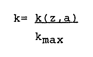
Worin kmax die maximale Bildamplitude darstellt. In diesem Falle wird also der Faktor k mit steigender Bildamplitude größer, so daß der Skalierungsfaktor G(k) mit steigender Bildamplitude kleiner wird, so daß die von den ursprünglichen Bildwerten abgezogenen Filterwerte ebenfalls kleiner werden, wodurch im Endeffekt die Filterwirkung vermindert wird.The scaling factor G (k) can be selected in various ways. The scaling factor is defined as
so k can be chosen in different ways. If, for example, the scaling factor is to be selected depending on the image amplitude, the following applies:
In which k max represents the maximum image amplitude. In this case, the factor k becomes larger with increasing image amplitude, so that the scaling factor G (k) becomes smaller with increasing image amplitude, so that the filter values subtracted from the original image values also become smaller, as a result of which the filter effect is reduced.
Für die Wahl des Skalierungsfaktors ist es aber auch möglich, nicht nur einfach die Bildhelligkeit zu berücksichtigen, sondern auch im Bereich der Bildpunkte, deren Bildwerte berechnet werden, den Verlauf des Signals zu berücksichtigen. Tritt z.B. in dem zu berechnenden Bildpunktbereich ein Signalsprung auf, so sollte dieser möglichst wenig beeinflußt werden. Dies kann durch folgende Wahl von k berücksichtigt werden.

For the selection of the scaling factor, it is also possible not only to simply take the image brightness into account, but also in the area of the pixels whose image values are calculated, the course of the signal to consider. If, for example, a signal jump occurs in the pixel area to be calculated, this should be influenced as little as possible. This can be taken into account by choosing k.
Worin der Faktor a zur Bewertung der Sprunghöhe dient, welche mittels der Differenz dargestellt ist, und wobei d berücksichtigt, in welchem Bildpunkt-Abstand in Zeilenrichtung die Sprunghöhe zu berücksichtigen ist.Where the factor a is used to evaluate the jump height, which is shown by means of the difference, and where d takes into account the pixel distance in the line direction of the jump height.
Bei der Berücksichtigung der Sprunghöhe kann darüberhinaus noch eine Art "Gedächtniswirkung" berücksichtigt werden, d.h. ein Nachwirken von Kontrastsprüngen auf ihre Umgebung erzielt werden. Dies kann dadurch geschehen, daß der zuvor ermittelte Wert von k₁ für den nächsten Wert nochmal berücksichtigt wird, wobei ein Faktor b die Gewichtung dieser Rückführung bestimmt. Es ergibt sich dann folgende Gleichung:

Bei dieser Wahl von k wird also sowohl eine aktuelle Sprunghöhe wie auch eine in dem benachbarten Bereich d zuvor bestimmte Sprunghöhe berücksichtigt. Es wird damit die Wirkung erzielt, daß im Bereich relativ starker Signaländerungen die Filterwirkung reduziert wird, daß jedoch in Bereichen mit geringen Signaländerungen eine relativ große Filterwirkung eintritt. Es werden damit in Bereichen, in denen mit großer Wahrscheinlichkeit kein Nutzsignal vorhanden ist, Bildstörungen besonders gut unterdrückt.When taking the jump height into account, a kind of "memory effect" can also be taken into account, ie an after-effect of contrast jumps on their surroundings can be achieved. This can be done by taking the previously determined value of k 1 into account again for the next value, a factor b determining the weighting of this feedback. The following equation then results:
With this choice of k, both a current jump height and a jump height previously determined in the adjacent area d are taken into account. The effect is achieved that the filter effect is reduced in the area of relatively strong signal changes, but that a relatively large filter effect occurs in areas with small signal changes. In this way, image interference is particularly well suppressed in areas in which there is a high probability of no useful signal being present.
Claims (8)
dadurch gekennzeichnet, daß die Bildwerte einem Analog/Digital- Umsetzer zugeführt und die umgesetzten Werte in einen Bildspeicher (6) eingelesen werden und daß ein Signalprozessor (7) vorgesehen ist, mittels dessen die Bildwerte jeweils benachbarter Bildpunkte einer Bildzeile mit einer Tiefpaßfilterfunktion und die Bildwerte in Abtastrichtung benachbarter Bildpunkte mit einer Hochpaßfilterfunktion beaufschlagt werden.Arrangement for scanning a charge image, which is generated on a previously locally evenly charged photoconductor (1) during an X-ray irradiation depending on its local intensity, by means of several electrometer probes (2) arranged in a row, which scan the charge pattern of the photoconductor (1) line by line , which is successively moved in the scanning direction perpendicular to the line direction, and which deliver an image value corresponding to the discharge at the image point for each pixel,
characterized in that the image values are fed to an analog / digital converter and the converted values are read into an image memory (6) and in that a signal processor (7) is provided by means of which the image values of respectively adjacent pixels of an image line with a low-pass filter function and the image values a high-pass filter function can be applied to adjacent pixels in the scanning direction.
dadurch gekennzeichnet, daß die Filterfunktionen mittels des Signalprozessors (7) und eines zweiten Bildspeichers (8) realisiert werden, indem die in dem ersten Bildspeicher eingelesenen Signalwerte mittels des Signalprozessors (7) in Zeilenrichtung mit einer Hochpaßfilterfunkton beaufschlagt und in dem zweiten Bildspeicher (8) zwischengespeichert werden, indem mittels des Signalprozessors (7) diese zwischengespeicherten Werte in Abtastrichtung mit einer Tiefpaßfilterfunktion beaufschlagt und wiederum in dem zweiten Bildspeicher zwischengespeichert werden und indem nach Berechnung aller Werte die in dem zweiten Bildspeicher (8) zwischengespeicherten Werte von den in dem ersten Bildspeicher (6) abgespeicherten Werten subtrahiert werden.Arrangement according to claim 1,
characterized in that the filter functions are implemented by means of the signal processor (7) and a second image memory (8) by applying a high-pass filter function to the signal values read in the first image memory by means of the signal processor (7) and in the second image memory (8) are temporarily stored by applying a low-pass filter function to these temporarily stored values in the scanning direction by means of the signal processor (7) and again in the second image memory are temporarily stored and in that after calculation of all values, the values temporarily stored in the second image memory (8) are subtracted from the values stored in the first image memory (6).
dadurch gekennzeichnet, daß die Filterfunktionen mittels des Signalprozessors (7) und eines zweiten Bildspeichers (8) realisiert werden, indem die in dem ersten Bildspeicher eingelesenen Signalwerte mittels des Signalprozessors (7) in Abtastrichtung mit einer Tiefpaßfilterfunkton beaufschlagt und in dem zweiten Bildspeicher (8) zwischengespeichert werden, indem mittels des Signalprozessors (7) diese zwischengespeicherten Werte in Zeilenrichtung mit einer Hochpaßfilterfunktion beaufschlagt und wiederum in dem zweiten Bildspeicher zwischengespeichert werden und indem nach Berechnung aller Werte die in dem zweiten Bildspeicher (8) zwischengespeicherten Werte von den in dem ersten Bildspeicher (6) abgespeicherten Werten subtrahiert werden.Arrangement according to claim 1,
characterized in that the filter functions are implemented by means of the signal processor (7) and a second image memory (8) by applying a low-pass filter function in the scanning direction to the signal values read in the first image memory by means of the signal processor (7) and in the second image memory (8) are temporarily stored by applying a high-pass filter function to these temporarily stored values in the line direction by means of the signal processor (7) and in turn being temporarily stored in the second image memory and, after all values have been calculated, the values temporarily stored in the second image memory (8) from those in the first image memory ( 6) stored values are subtracted.
dadurch gekennzeichnet, daß die in dem zweiten Bildspeicher (8) abgespeicherten Werte vor Subtraktion von den in dem ersten Bildspeicher abgespeicherten Bildwerten mittels des Signalprozessors mit einem Skalierungsfaktor multipliziert werden, der der Einstellung der Stärke der Filterwirkung dient.Arrangement according to claim 2 or 3,
characterized in that the values stored in the second image memory (8) are subtracted from the image values stored in the first image memory by means of the signal processor by a scaling factor which serves to adjust the strength of the filter effect.
dadurch gekennzeichnet, daß die Größe des Skalierungsfaktors in Abhängigkeit der von den Bildwerten repräsentierten Bildamplitude so gewählt wird, daß er in stark belichteten Bildbereichen relativ klein ist.Arrangement according to claim 4,
characterized in that the size of the scaling factor is selected as a function of the image amplitude represented by the image values so that it is relatively small in strongly exposed image areas.
dadurch gekennzeichnet, daß die Größe des Skalierungsfaktors in Abhängigkeit des Signalverlaufs im Bereich um einen Bildwert so gewählt wird, daß der Skalierungsfaktor im Bereich starker Signalsprünge relativ klein gewählt wird.Arrangement according to claim 4,
characterized in that the size of the scaling factor is selected as a function of the signal curve in the area around an image value such that the scaling factor is selected to be relatively small in the area of strong signal jumps.
dadurch gekennzeichnet, daß die Filterfunktionen mittels zweier eindimensionaler Filterfunktionen realisiert werden.Arrangement according to one of claims 1 to 6,
characterized in that the filter functions are implemented by means of two one-dimensional filter functions.
dadurch gekennzeichnet, daß zur Erzeugung eines Röntgenbildes eine Anordnung nach einem der vorhergehenden Ansprüche vorgesehen ist.X-ray examination device with a source for generating X-rays,
characterized in that an arrangement according to one of the preceding claims is provided for generating an X-ray image.
Applications Claiming Priority (2)
| Application Number | Priority Date | Filing Date | Title |
|---|---|---|---|
| DE4006181 | 1990-02-28 | ||
| DE4006181A DE4006181A1 (en) | 1990-02-28 | 1990-02-28 | ARRANGEMENT FOR SCANING AN X-RAY IMAGE |
Publications (3)
| Publication Number | Publication Date |
|---|---|
| EP0444737A2 true EP0444737A2 (en) | 1991-09-04 |
| EP0444737A3 EP0444737A3 (en) | 1992-04-29 |
| EP0444737B1 EP0444737B1 (en) | 1995-08-16 |
Family
ID=6401074
Family Applications (1)
| Application Number | Title | Priority Date | Filing Date |
|---|---|---|---|
| EP91200358A Expired - Lifetime EP0444737B1 (en) | 1990-02-28 | 1991-02-20 | Device for scanning a radiography |
Country Status (4)
| Country | Link |
|---|---|
| US (1) | US6058220A (en) |
| EP (1) | EP0444737B1 (en) |
| JP (1) | JP2962527B2 (en) |
| DE (2) | DE4006181A1 (en) |
Cited By (1)
| Publication number | Priority date | Publication date | Assignee | Title |
|---|---|---|---|---|
| EP0642265A1 (en) * | 1993-09-08 | 1995-03-08 | Philips Patentverwaltung GmbH | Method and apparatus for generating X ray exposures |
Families Citing this family (5)
| Publication number | Priority date | Publication date | Assignee | Title |
|---|---|---|---|---|
| US8923956B2 (en) | 2001-12-07 | 2014-12-30 | The University Of Sussex | Electrodynamic sensors and applications thereof |
| GB0129390D0 (en) * | 2001-12-07 | 2002-01-30 | Clark Terrence D | Electrodynamic sensors and applications thereof |
| US7426314B2 (en) * | 2004-07-30 | 2008-09-16 | Hewlett-Packard Development Company, L.P. | Adjusting pixels by desired gains and factors |
| US7860334B2 (en) * | 2006-02-09 | 2010-12-28 | Qualcomm Incorporated | Adaptive image filter for filtering image information |
| JP5538684B2 (en) * | 2008-03-13 | 2014-07-02 | キヤノン株式会社 | Image processing apparatus, image processing method, program, and storage medium |
Family Cites Families (14)
| Publication number | Priority date | Publication date | Assignee | Title |
|---|---|---|---|---|
| US4328425A (en) * | 1980-08-04 | 1982-05-04 | Xerox Corporation | Filter for image pixels |
| DE3417386A1 (en) * | 1984-05-10 | 1985-11-14 | Siemens AG, 1000 Berlin und 8000 München | Television device having filter means with a local-frequency high-pass characteristic |
| US4677461A (en) * | 1984-07-26 | 1987-06-30 | Mitsubishi Denki Kabushiki Kaisha | Contour detecting filter |
| US4706113A (en) * | 1985-02-18 | 1987-11-10 | Mitsubishi Denki Kabushiki Kaisha | Contour detecting filter device using PAL samples of composite video signals without separation of luminance signals therefrom |
| DE3529108A1 (en) * | 1985-08-14 | 1987-02-26 | Philips Patentverwaltung Gmbh, 2000 Hamburg | METHOD FOR PRODUCING AN X-RAY IMAGING BY MEANS OF A PHOTOConductor and ARRANGEMENT FOR IMPLEMENTING THE METHOD |
| US4821337A (en) * | 1985-10-30 | 1989-04-11 | Alm Ake W | Radiation scanner uniformity system |
| US4789890A (en) * | 1985-12-05 | 1988-12-06 | Mitsubishi Denki Kabushiki Kaisha | Judgement circuit and adaptive filter incorporating the same |
| DE3629409C2 (en) * | 1986-08-29 | 1994-02-17 | Agfa Gevaert Ag | Method and device for contrast evaluation in electronic image processing |
| US4954885A (en) * | 1987-02-25 | 1990-09-04 | Mitsubishi Denki Kabushiki Kaisha | Filter for separating luminance and chrominance signals from composite color television signal |
| US4908697A (en) * | 1987-07-24 | 1990-03-13 | North American Philips Corporation | Two-line mac high definition television system |
| US4999701A (en) * | 1987-11-17 | 1991-03-12 | North American Philips Corporation | High definition NTSC compatible television system with increased horizontal bandwidth and reduced color artifacts |
| DE3817027A1 (en) * | 1988-05-19 | 1989-11-30 | Philips Patentverwaltung | METHOD FOR GENERATING AN X-RAY IMAGING BY MEANS OF A PHOTO CONDUCTOR, AND ARRANGEMENT FOR IMPLEMENTING THE METHOD |
| US4912569A (en) * | 1989-01-24 | 1990-03-27 | Eastman Kodak Company | Method for thresholding an image signal |
| US5003618A (en) * | 1989-07-14 | 1991-03-26 | University Of Pittsburgh Of The Commonwealth System Of Higher Education | Automatic adaptive anisotropic digital filtering and biasing of digitized images |
-
1990
- 1990-02-28 DE DE4006181A patent/DE4006181A1/en not_active Withdrawn
-
1991
- 1991-02-20 EP EP91200358A patent/EP0444737B1/en not_active Expired - Lifetime
- 1991-02-20 DE DE59106237T patent/DE59106237D1/en not_active Expired - Fee Related
- 1991-02-26 JP JP3030841A patent/JP2962527B2/en not_active Expired - Lifetime
-
1993
- 1993-11-24 US US08/157,842 patent/US6058220A/en not_active Expired - Fee Related
Cited By (1)
| Publication number | Priority date | Publication date | Assignee | Title |
|---|---|---|---|---|
| EP0642265A1 (en) * | 1993-09-08 | 1995-03-08 | Philips Patentverwaltung GmbH | Method and apparatus for generating X ray exposures |
Also Published As
| Publication number | Publication date |
|---|---|
| EP0444737B1 (en) | 1995-08-16 |
| US6058220A (en) | 2000-05-02 |
| JP2962527B2 (en) | 1999-10-12 |
| DE4006181A1 (en) | 1991-08-29 |
| EP0444737A3 (en) | 1992-04-29 |
| DE59106237D1 (en) | 1995-09-21 |
| JPH06103376A (en) | 1994-04-15 |
Similar Documents
| Publication | Publication Date | Title |
|---|---|---|
| EP0212733B1 (en) | Method and apparatus for the production of X-ray images using photoconductors | |
| DE3826288C2 (en) | ||
| DE69425416T2 (en) | Image composition method and image forming apparatus for carrying out this method | |
| DE2952422C3 (en) | Method and device for processing an X-ray image in an X-ray image copying system | |
| EP0681269B1 (en) | Method and apparatus for reproducing a radiograph as a visible image | |
| DE60224770T2 (en) | Method and apparatus for noise reduction in computer tomographs | |
| DE3704685C2 (en) | ||
| DE69011194T2 (en) | X-ray image processing device. | |
| DE69128954T2 (en) | Computed tomography | |
| EP0379748B1 (en) | Method and arrangement for producing x-ray photographs using photoconductors | |
| DE3406905A1 (en) | ROENTGENGERAET | |
| DE3441165A1 (en) | METHOD AND DEVICE FOR IMPROVING THE IMAGE | |
| DE68927031T2 (en) | Method for determining the desired areas of an image signal and method for determining the desired image areas | |
| DE2702009A1 (en) | RADIOGRAPHIC DEVICE | |
| DE2720994C2 (en) | Device for reconstructing tomograms | |
| DE602005004410T2 (en) | SYSTEM AND METHOD FOR CORRECTING TEMPORARY ARTEFACT IN TOMOGRAPHIC IMAGES | |
| DE10135427A1 (en) | Areal image detector for electromagnetic rays, especially X-rays | |
| EP1202561B1 (en) | Apparatus and method for reading out several sets of pixels with different sampling rates | |
| DE2532716B2 (en) | Device for generating a representation of the absorption distribution of radiation in a cross-sectional slice of a body | |
| EP0444737B1 (en) | Device for scanning a radiography | |
| EP0342760B1 (en) | Method for producing an X-ray picture using photoconductors and device for carrying out this method | |
| DE19860036C1 (en) | Process to reduce row or line correlated noise in digital image sensor | |
| DE19748668A1 (en) | Non-Uniformity Correction of a Detector Z-Axis Gain in a Computer Tomography System | |
| EP0558116B1 (en) | Method for radiograms and device suited therefor | |
| EP0517302B1 (en) | Arrangement for producing X-ray photographs |
Legal Events
| Date | Code | Title | Description |
|---|---|---|---|
| PUAI | Public reference made under article 153(3) epc to a published international application that has entered the european phase |
Free format text: ORIGINAL CODE: 0009012 |
|
| AK | Designated contracting states |
Kind code of ref document: A2 Designated state(s): DE FR GB |
|
| PUAL | Search report despatched |
Free format text: ORIGINAL CODE: 0009013 |
|
| AK | Designated contracting states |
Kind code of ref document: A3 Designated state(s): DE FR GB |
|
| 17P | Request for examination filed |
Effective date: 19921029 |
|
| 17Q | First examination report despatched |
Effective date: 19940725 |
|
| GRAA | (expected) grant |
Free format text: ORIGINAL CODE: 0009210 |
|
| AK | Designated contracting states |
Kind code of ref document: B1 Designated state(s): DE FR GB |
|
| REF | Corresponds to: |
Ref document number: 59106237 Country of ref document: DE Date of ref document: 19950921 |
|
| GBT | Gb: translation of ep patent filed (gb section 77(6)(a)/1977) |
Effective date: 19951115 |
|
| ET | Fr: translation filed | ||
| PLBE | No opposition filed within time limit |
Free format text: ORIGINAL CODE: 0009261 |
|
| STAA | Information on the status of an ep patent application or granted ep patent |
Free format text: STATUS: NO OPPOSITION FILED WITHIN TIME LIMIT |
|
| 26N | No opposition filed | ||
| REG | Reference to a national code |
Ref country code: FR Ref legal event code: CD |
|
| PGFP | Annual fee paid to national office [announced via postgrant information from national office to epo] |
Ref country code: FR Payment date: 20000222 Year of fee payment: 10 |
|
| PGFP | Annual fee paid to national office [announced via postgrant information from national office to epo] |
Ref country code: GB Payment date: 20000228 Year of fee payment: 10 |
|
| PGFP | Annual fee paid to national office [announced via postgrant information from national office to epo] |
Ref country code: DE Payment date: 20000419 Year of fee payment: 10 |
|
| PG25 | Lapsed in a contracting state [announced via postgrant information from national office to epo] |
Ref country code: GB Free format text: LAPSE BECAUSE OF NON-PAYMENT OF DUE FEES Effective date: 20010220 |
|
| GBPC | Gb: european patent ceased through non-payment of renewal fee |
Effective date: 20010220 |
|
| PG25 | Lapsed in a contracting state [announced via postgrant information from national office to epo] |
Ref country code: FR Free format text: LAPSE BECAUSE OF NON-PAYMENT OF DUE FEES Effective date: 20011031 |
|
| REG | Reference to a national code |
Ref country code: FR Ref legal event code: ST |
|
| PG25 | Lapsed in a contracting state [announced via postgrant information from national office to epo] |
Ref country code: DE Free format text: LAPSE BECAUSE OF NON-PAYMENT OF DUE FEES Effective date: 20011201 |