EP0444743B1 - Attache et profilé pour fixer un store horizontal dans une serre - Google Patents
Attache et profilé pour fixer un store horizontal dans une serre Download PDFInfo
- Publication number
- EP0444743B1 EP0444743B1 EP91200384A EP91200384A EP0444743B1 EP 0444743 B1 EP0444743 B1 EP 0444743B1 EP 91200384 A EP91200384 A EP 91200384A EP 91200384 A EP91200384 A EP 91200384A EP 0444743 B1 EP0444743 B1 EP 0444743B1
- Authority
- EP
- European Patent Office
- Prior art keywords
- section
- bracket
- edge
- leg
- free
- Prior art date
- Legal status (The legal status is an assumption and is not a legal conclusion. Google has not performed a legal analysis and makes no representation as to the accuracy of the status listed.)
- Expired - Lifetime
Links
- 229910052751 metal Inorganic materials 0.000 claims description 3
- 239000002184 metal Substances 0.000 claims description 3
- 239000004677 Nylon Substances 0.000 description 1
- 239000004411 aluminium Substances 0.000 description 1
- 229910052782 aluminium Inorganic materials 0.000 description 1
- XAGFODPZIPBFFR-UHFFFAOYSA-N aluminium Chemical compound [Al] XAGFODPZIPBFFR-UHFFFAOYSA-N 0.000 description 1
- 239000004744 fabric Substances 0.000 description 1
- 229920001778 nylon Polymers 0.000 description 1
- 239000004033 plastic Substances 0.000 description 1
- 238000009423 ventilation Methods 0.000 description 1
Images


Classifications
-
- A—HUMAN NECESSITIES
- A01—AGRICULTURE; FORESTRY; ANIMAL HUSBANDRY; HUNTING; TRAPPING; FISHING
- A01G—HORTICULTURE; CULTIVATION OF VEGETABLES, FLOWERS, RICE, FRUIT, VINES, HOPS OR SEAWEED; FORESTRY; WATERING
- A01G9/00—Cultivation in receptacles, forcing-frames or greenhouses; Edging for beds, lawn or the like
- A01G9/22—Shades or blinds for greenhouses, or the like
-
- Y—GENERAL TAGGING OF NEW TECHNOLOGICAL DEVELOPMENTS; GENERAL TAGGING OF CROSS-SECTIONAL TECHNOLOGIES SPANNING OVER SEVERAL SECTIONS OF THE IPC; TECHNICAL SUBJECTS COVERED BY FORMER USPC CROSS-REFERENCE ART COLLECTIONS [XRACs] AND DIGESTS
- Y02—TECHNOLOGIES OR APPLICATIONS FOR MITIGATION OR ADAPTATION AGAINST CLIMATE CHANGE
- Y02A—TECHNOLOGIES FOR ADAPTATION TO CLIMATE CHANGE
- Y02A40/00—Adaptation technologies in agriculture, forestry, livestock or agroalimentary production
- Y02A40/10—Adaptation technologies in agriculture, forestry, livestock or agroalimentary production in agriculture
- Y02A40/25—Greenhouse technology, e.g. cooling systems therefor
Definitions
- the invention relates to a bracket of resilient metal wire according to the preamble of claim 1.
- the invention also relates to a section for accommodating such a bracket according to the preamble of claim 4.
- the known bracket is used to guide the section along chords pulled taut above and below the shade of a shading structure in a greenhouse or a glasshouse. Separate clips are used to join the shade to the section, and the section has an extra thickened edge.
- the know bracket thus serves only for guiding along the taut chords, the two legs of the bracket in that case being equal to each other.
- the object of the invention is to provide a bracket which, apart from its guiding purpose, can also be used for fixing the shade to the section, as a result of which clips are not needed, a better fixing is obtained, and less light loss occurs.
- bracket according to the invention is designed according to the characterising part of claim 1.
- the object of the invention is to provide a section intended for accommodating brackets such as according to the invention, and which differs from the known sections as indicated above. With such a section, it is allowed that the bracket is mounted on either the one or the other side of that section.
- the section is characterised by the features according to claim 4.
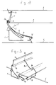
- a shade section extruded from aluminium is indicated by 1 and generally runs horizontally in a greenhouse or glasshouse at the level of the gutters.
- a section of this type is known in practice and is moved parallel to itself in order to open or to close a flexible shade 2 made of cloth or sheeting.
- the shade section 1 can be moved parallel to itself in the horizontal direction. On movement to the left the shade 2 is folded out, so that the space in the greenhouse below the shade 2 is better shut off from temperature variations.
- Nylon cords are pulled taut between the bars in the greenhouse in order to ensure that the folded shade 2 does not project too much.
- the top taut cords are indicated by 3, and the bottom cords by 4.
- the bottom cords 4 serve to support the weight of the folded shade 2, and the top cords 3 to prevent flying up when the ventilation windows are open.
- the right end of the shade 2 is fixed at the right side to a fixed bar which is a distance away from the fixed bar against which the shade section 1 rests when the shade 2 is closed.
- brackets 5 made of resilient metal wire are used as a guide along the cords 3 and 4.
- One such known bracket 5 is shown on the right in Fig. 1, is clamped around the edges 1a and 1b of the section 1, and forms a wide opening for the cord 3.
- brackets 5 are clamped around the edges 1c and 1d of the section 1, and then form a wide opening for the cord 4.
- Every known shade section 1 thus has a large number of such brackets 5, the number on the top side generally being half the number on the bottom side.
- the known shade sections also have a projecting edge 6 with thickened end 7, which is shown by dot-and-dash lines in Fig. 2.
- the left edge of the shade 2 is then folded round the thickened end 7 and the shade is fixed by means of a sort of clip on the projecting edge 6, 7.
- These clips are generally made of plastic and when fitted clamp the folded edge of the shade 2 against the projecting edge 6, 7.
- the brackets used for guiding along the cords 3 and 4 are modified in such a way that they can also be used for fixing the shade to the section 1.
- Such a bracket is indicated by 8 on the left in Fig. 1.
- This bracket 8 is largely the same as the known bracket 5, but one leg 8a is extended and bent back, while the free end 8b grips behind the edge 1c of the section 1.
- the bent-back leg 8a is so long that the bend 8c rests resiliently against the edge 1b of the section 1.
- the free edge 2a of the shade 2 is then laid in the channel formed by the edge 1b, and the bend 8c of the bracket 8 presses the free edge 2a against the channel.
- brackets 8 remain on the section 1 when the shade 2 is pulled away from the section 1.
- the free edge 2a of the shade 2 can also engage in the channel formed by the edge 1c and is then pressed by a bracket 8 which also engages on the edges 1a and 1b of the section 1.
- section 1 is to a certain extent symmetrical, i.e. the distance between the edges 1d and 1b is equal to the distance between the edges 1a and 1c, and the edge 6, 7 is omitted.
- the shade 2 is fixed at such a point on the section 1 that as little light loss as possible occurs.
- the bracket can, of course, also be made differently.
- FIG. 3 Another embodiment of the clamping bracket is shown in Fig. 3 in a perspective view.
- This clamping bracket is indicated by 9 and largely corresponds to the clamping bracket 8, except that the right leg is different.
- the extended leg 9a is first folded inwards at 9b, in order to engage behind the edge 1c of the section 1, and then runs into a curved edge 9c which can clamp the edge of the shade 2 in the channel formed by the edge 1b of the section 1, in the same way as the bend 8c of the bracket 8.
- FIG. 4 Yet another embodiment of the clamping bracket is shown in Fig. 4 and is indicated by 10.
- the bracket 10 has features of the bracket 8 and of the bracket 9, and is preferred.
- the right leg of the bracket 10 is conventional.
- the left leg 10a is first folded around the edge 1c, like the bracket 9 at 10b. At 10c the leg 10a is folded back and with the free end 10d engages in the channel formed by the edge 1c.
Landscapes
- Life Sciences & Earth Sciences (AREA)
- Environmental Sciences (AREA)
- Clamps And Clips (AREA)
Claims (5)
- Attache en fil métallique élastique destinée à fixer un profilé sur une structure de store dans une serre ou une verrière, le profilé disposant d'une première et d'une seconde surfaces espacées l'une par rapport à l'autre d'environ 90°, ladite première surface définissant un deuxième bord libre (1b) faisant face à la seconde surface et ladite seconde surface définissant un troisième (1c) et un quatrième (1d) bords libres orientés de façon opposée l'un par rapport à l'autre, lesdits deuxième et troisième bords libres étant mutuellement plus proche que lesdits deuxième et quatrième bords libres, des sections en canal rejoignant lesdits deuxième et troisième bords libres pour permettre aux parties de l'attache de se mettre en prise sous lesdits deuxième et troisième bords libres, le profilé définissant un espacement non interrompu entre les deux canaux, et étant par exemple conforme à la revendication 4, ladite attache (8; 9; 10) comprenant des première et seconde jambes espacées l'une par rapport à l'autre et reliées à une extrémité par une pièce transversale, l'attache présentant par ce moyen globalement une forme de U et lesdites jambes reposant partiellement dans un plan commun, chaque jambe présentant une première courbure, et, dans une direction globalement perpendiculaire audit plan commun, pour former une première partie en crochet pour la mise en prise avec le quatrième bord libre dudit profilé, au moins une jambe disposant, à une certaine distance de ladite courbure, une seconde courbure dans un sens opposé à celui de ladite première courbure dans le but de définir une seconde partie en crochet pour la mise en prise avec le troisième bord libre dudit profilé, l'autre jambe disposant d'au moins une partie (8b; 9b; 10b) pour la mise en prise sous le troisième bord libre dudit profilé, caractérisée en ce que ladite autre jambe dispose aussi d'au moins une partie (8c; 9c; 10c) pour la mise en prise sous le deuxième bord libre dudit profilé, ladite partie se mettant en prise sous ledit deuxième bord libre étant située sur une extension (8a; 9a; 10a) de ladite autre jambe disposée au-delà de ladite distance par rapport à ladite première courbure.
- Attache selon la revendication 1, dans laquelle ladite extension est en forme de boucle, de façon que deux parties en fil s'étendent entre le deuxième profil en crochet (1b) et le premier profil en crochet (1c) avec l'extrémité libre de la seconde jambe se mettant en prise dans le troisième profil en crochet (1c).
- Attache selon la revendication 1 ou 2, dans laquelle, mise à part l'extension (8a; 9a; 10a) de la seconde jambe, lesdites première et seconde jambes présentent une forme globalement similaire.
- Profilé pour recevoir les attaches selon l'une quelconque des revendications précédentes, disposant d'une première et d'une seconde surfaces espacées l'une par rapport à l'autre d'approximativement 90°, ladite première surface définissant un premier (1a) et un deuxième (1b) bords libres orientés de façon opposée l'un par rapport à l'autre et ladite seconde surface définissant un troisième (1c) et un quatrième (1d) bords libres dirigés de façon opposée l'un par rapport à l'auteur, lesdits deuxième et troisième bords libres étant mutuellement plus proches que lesdits premier et quatrième bords libres, des sections en canal rejoignant lesdits deuxième et troisième bords libres pour permettre aux parties de l'attache de se mettre en prise sous lesdits deuxième et troisième bords libres, caractérisé en ce que la distance entre le premier bord et la base du troisième canal de bord est égale à la distance entre le quatrième bord et la base du deuxième canal de bord, les distances entre les premier et deuxième bords et les troisième et quatrième bords étant respectivement égales, ce par quoi, l'attache peut être montée soit sur la première soit sur la seconde surface avec l'extension se mettant respectivement en prise sur le troisième canal de bord ou le deuxième canal de bord, le profilé définissant un espacement ininterrompu entre les deux canaux pour permettre à l'extension de l'attache de se situer entre un canal et l'autre canal ou son bord associe.
- Profilé selon la revendication 4, dans lequel lesdits plans de fixation sont étagés par rapport à la jambe mutuelle dudit profilé, vers le côté faisant face au plan de fixation opposé, et chaque plan de fixation s'étendant latéralement sur les deux côtés de la position de liaison avec la jambe mutuelle dudit profilé.
Applications Claiming Priority (2)
| Application Number | Priority Date | Filing Date | Title |
|---|---|---|---|
| NL9000479 | 1990-02-28 | ||
| NL9000479A NL9000479A (nl) | 1990-02-28 | 1990-02-28 | Beugel en profiel bestemd voor het bevestigen van een horizontaal scherm in een kas of warenhuis. |
Publications (2)
| Publication Number | Publication Date |
|---|---|
| EP0444743A1 EP0444743A1 (fr) | 1991-09-04 |
| EP0444743B1 true EP0444743B1 (fr) | 1995-05-03 |
Family
ID=19856678
Family Applications (1)
| Application Number | Title | Priority Date | Filing Date |
|---|---|---|---|
| EP91200384A Expired - Lifetime EP0444743B1 (fr) | 1990-02-28 | 1991-02-22 | Attache et profilé pour fixer un store horizontal dans une serre |
Country Status (3)
| Country | Link |
|---|---|
| EP (1) | EP0444743B1 (fr) |
| DE (1) | DE69109349T2 (fr) |
| NL (1) | NL9000479A (fr) |
Cited By (1)
| Publication number | Priority date | Publication date | Assignee | Title |
|---|---|---|---|---|
| NL1014244C2 (nl) * | 2000-02-01 | 2001-08-03 | Valk Systemen Bvvd | Scherminrichting in een kas, alsmede draadklem daarvoor. |
Families Citing this family (5)
| Publication number | Priority date | Publication date | Assignee | Title |
|---|---|---|---|---|
| NL1033715C2 (nl) * | 2007-02-13 | 2008-08-14 | Metaal En Kunststoffen Ind Sne | Bevestigingsbeugel. |
| DE202008013436U1 (de) | 2008-10-13 | 2009-01-29 | Novavert Gmbh & Co. Kg | Gewächshaus mit Abschattungsvorrichtung und Befestigungsprofil |
| NL2002321C2 (nl) | 2008-12-12 | 2010-06-15 | Valk Systemen Bvvd | Set uit op elkaar gestapelde schermprofielen, samenstelling uit meerdere van dergelijke naast elkaar geplaatste sets alsmede schermprofiel. |
| NL2004130C2 (nl) * | 2010-01-22 | 2012-03-05 | Bordeso Bv | Schermsysteem voor een warenhuis. |
| DE102014109443B4 (de) | 2013-11-20 | 2019-09-12 | Werner Heinze | Klemmbügel |
Citations (1)
| Publication number | Priority date | Publication date | Assignee | Title |
|---|---|---|---|---|
| EP0338925A1 (fr) * | 1988-04-22 | 1989-10-25 | Fernand Scherrer | Faux-plafond constitué par une nappe tendue accrochée, le long de ses bords, à un support fixé aux murs d'une pièce d'un bâtiment |
Family Cites Families (1)
| Publication number | Priority date | Publication date | Assignee | Title |
|---|---|---|---|---|
| US3719013A (en) * | 1971-02-12 | 1973-03-06 | O Blick | Moulding for suspension mounting and decoration purposes |
-
1990
- 1990-02-28 NL NL9000479A patent/NL9000479A/nl not_active Application Discontinuation
-
1991
- 1991-02-22 DE DE69109349T patent/DE69109349T2/de not_active Expired - Fee Related
- 1991-02-22 EP EP91200384A patent/EP0444743B1/fr not_active Expired - Lifetime
Patent Citations (1)
| Publication number | Priority date | Publication date | Assignee | Title |
|---|---|---|---|---|
| EP0338925A1 (fr) * | 1988-04-22 | 1989-10-25 | Fernand Scherrer | Faux-plafond constitué par une nappe tendue accrochée, le long de ses bords, à un support fixé aux murs d'une pièce d'un bâtiment |
Cited By (1)
| Publication number | Priority date | Publication date | Assignee | Title |
|---|---|---|---|---|
| NL1014244C2 (nl) * | 2000-02-01 | 2001-08-03 | Valk Systemen Bvvd | Scherminrichting in een kas, alsmede draadklem daarvoor. |
Also Published As
| Publication number | Publication date |
|---|---|
| DE69109349D1 (de) | 1995-06-08 |
| DE69109349T2 (de) | 1996-01-04 |
| EP0444743A1 (fr) | 1991-09-04 |
| NL9000479A (nl) | 1991-09-16 |
Similar Documents
| Publication | Publication Date | Title |
|---|---|---|
| US4518025A (en) | Sun blind construction | |
| US4557310A (en) | Movable sun shade system | |
| US5141192A (en) | Apparatus for hanging cords from a gutter or the like | |
| US5275221A (en) | Guide rod for window decorations or shading systems | |
| AU604230B2 (en) | False ceiling or false wall constituted by a stretched sheet fastened | |
| US4739816A (en) | Venetian blind system for greenhouses | |
| DE3775406D1 (en) | Waescheaufhaengevorrichtung. | |
| US5388802A (en) | Method and apparatus for suspending Christmas lights underneath eaves on a house | |
| US5275381A (en) | Wire fencing with decorative slats that provide essentially complete privacy | |
| KR101284944B1 (ko) | 건축물 개방구용의 단일 트랙의 스태킹 패널 커버링 | |
| EP0444743B1 (fr) | Attache et profilé pour fixer un store horizontal dans une serre | |
| EP0120425A2 (fr) | Support de rideau et système pour ouvrir et fermer des rideaux | |
| US4793396A (en) | Adjustable fabric retainer for a window blind | |
| US6739374B1 (en) | Method and apparatus for retaining slats of a vertical blind | |
| US1899062A (en) | Splint shade support | |
| US6935078B1 (en) | Anchor fastener clip | |
| US4237958A (en) | Drapery connector assembly | |
| EP0569355B1 (fr) | Crochet servant a accrocher un tissu, et tissu destine a etre utilise avec ce crochet | |
| CA2021278C (fr) | Appareil permettant l'assemblage de branches pliables, a un arbre artificiel | |
| US2706521A (en) | Fascia board and curtain rod mounting bracket | |
| US3971427A (en) | Venetian blind profiled slats | |
| US6173544B1 (en) | Ceiling system and also a lath suitable for such a ceiling system | |
| US3470578A (en) | Drapery rod and bracket | |
| US2785445A (en) | Plastic awning construction | |
| AU2003275903B2 (en) | Curtain system comprising several flat panels |
Legal Events
| Date | Code | Title | Description |
|---|---|---|---|
| PUAI | Public reference made under article 153(3) epc to a published international application that has entered the european phase |
Free format text: ORIGINAL CODE: 0009012 |
|
| AK | Designated contracting states |
Kind code of ref document: A1 Designated state(s): BE DE GB NL |
|
| 17P | Request for examination filed |
Effective date: 19911213 |
|
| 17Q | First examination report despatched |
Effective date: 19921208 |
|
| GRAA | (expected) grant |
Free format text: ORIGINAL CODE: 0009210 |
|
| AK | Designated contracting states |
Kind code of ref document: B1 Designated state(s): BE DE GB NL |
|
| REF | Corresponds to: |
Ref document number: 69109349 Country of ref document: DE Date of ref document: 19950608 |
|
| PLBE | No opposition filed within time limit |
Free format text: ORIGINAL CODE: 0009261 |
|
| STAA | Information on the status of an ep patent application or granted ep patent |
Free format text: STATUS: NO OPPOSITION FILED WITHIN TIME LIMIT |
|
| 26N | No opposition filed | ||
| REG | Reference to a national code |
Ref country code: GB Ref legal event code: IF02 |
|
| PGFP | Annual fee paid to national office [announced via postgrant information from national office to epo] |
Ref country code: GB Payment date: 20020204 Year of fee payment: 12 |
|
| NLT1 | Nl: modifications of names registered in virtue of documents presented to the patent office pursuant to art. 16 a, paragraph 1 |
Owner name: VAN DER VALK SYSTEMEN B.V. |
|
| PG25 | Lapsed in a contracting state [announced via postgrant information from national office to epo] |
Ref country code: GB Free format text: LAPSE BECAUSE OF NON-PAYMENT OF DUE FEES Effective date: 20030222 |
|
| GBPC | Gb: european patent ceased through non-payment of renewal fee | ||
| PGFP | Annual fee paid to national office [announced via postgrant information from national office to epo] |
Ref country code: DE Payment date: 20080310 Year of fee payment: 18 |
|
| PG25 | Lapsed in a contracting state [announced via postgrant information from national office to epo] |
Ref country code: DE Free format text: LAPSE BECAUSE OF NON-PAYMENT OF DUE FEES Effective date: 20090901 |
|
| PGFP | Annual fee paid to national office [announced via postgrant information from national office to epo] |
Ref country code: BE Payment date: 20100222 Year of fee payment: 20 |
|
| BE20 | Be: patent expired |
Owner name: *VAN DER VALK SYSTEMEN B.V. Effective date: 20110222 |
|
| REG | Reference to a national code |
Ref country code: NL Ref legal event code: V4 Effective date: 20110222 |
|
| PG25 | Lapsed in a contracting state [announced via postgrant information from national office to epo] |
Ref country code: NL Free format text: LAPSE BECAUSE OF EXPIRATION OF PROTECTION Effective date: 20110222 |
|
| PGFP | Annual fee paid to national office [announced via postgrant information from national office to epo] |
Ref country code: NL Payment date: 20100228 Year of fee payment: 20 |