EP0444776B1 - Dispositif et méthode de couplage - Google Patents
Dispositif et méthode de couplage Download PDFInfo
- Publication number
- EP0444776B1 EP0444776B1 EP91300550A EP91300550A EP0444776B1 EP 0444776 B1 EP0444776 B1 EP 0444776B1 EP 91300550 A EP91300550 A EP 91300550A EP 91300550 A EP91300550 A EP 91300550A EP 0444776 B1 EP0444776 B1 EP 0444776B1
- Authority
- EP
- European Patent Office
- Prior art keywords
- dovetail
- parts
- counterbore
- protrusion
- recess
- Prior art date
- Legal status (The legal status is an assumption and is not a legal conclusion. Google has not performed a legal analysis and makes no representation as to the accuracy of the status listed.)
- Expired - Lifetime
Links
Images

Classifications
-
- A—HUMAN NECESSITIES
- A61—MEDICAL OR VETERINARY SCIENCE; HYGIENE
- A61B—DIAGNOSIS; SURGERY; IDENTIFICATION
- A61B17/00—Surgical instruments, devices or methods
-
- B—PERFORMING OPERATIONS; TRANSPORTING
- B25—HAND TOOLS; PORTABLE POWER-DRIVEN TOOLS; MANIPULATORS
- B25B—TOOLS OR BENCH DEVICES NOT OTHERWISE PROVIDED FOR, FOR FASTENING, CONNECTING, DISENGAGING, OR HOLDING
- B25B23/00—Details of, or accessories for, spanners, wrenches, screwdrivers
- B25B23/0007—Connections or joints between tool parts
- B25B23/0035—Connection means between socket or screwdriver bit and tool
-
- A—HUMAN NECESSITIES
- A61—MEDICAL OR VETERINARY SCIENCE; HYGIENE
- A61B—DIAGNOSIS; SURGERY; IDENTIFICATION
- A61B17/00—Surgical instruments, devices or methods
- A61B17/16—Instruments for performing osteoclasis; Drills or chisels for bones; Trepans
- A61B17/1613—Component parts
- A61B17/1631—Special drive shafts, e.g. flexible shafts
-
- B—PERFORMING OPERATIONS; TRANSPORTING
- B23—MACHINE TOOLS; METAL-WORKING NOT OTHERWISE PROVIDED FOR
- B23B—TURNING; BORING
- B23B51/00—Tools for drilling machines
- B23B51/12—Adapters for drills or chucks; Tapered sleeves
- B23B51/126—Tool elongating devices
-
- B—PERFORMING OPERATIONS; TRANSPORTING
- B25—HAND TOOLS; PORTABLE POWER-DRIVEN TOOLS; MANIPULATORS
- B25B—TOOLS OR BENCH DEVICES NOT OTHERWISE PROVIDED FOR, FOR FASTENING, CONNECTING, DISENGAGING, OR HOLDING
- B25B23/00—Details of, or accessories for, spanners, wrenches, screwdrivers
- B25B23/0007—Connections or joints between tool parts
- B25B23/0021—Prolongations interposed between handle and tool
-
- B—PERFORMING OPERATIONS; TRANSPORTING
- B25—HAND TOOLS; PORTABLE POWER-DRIVEN TOOLS; MANIPULATORS
- B25G—HANDLES FOR HAND IMPLEMENTS
- B25G3/00—Attaching handles to the implements
- B25G3/02—Socket, tang, or like fixings
- B25G3/08—Socket, tang, or like fixings with dovetail or other groove
-
- Y—GENERAL TAGGING OF NEW TECHNOLOGICAL DEVELOPMENTS; GENERAL TAGGING OF CROSS-SECTIONAL TECHNOLOGIES SPANNING OVER SEVERAL SECTIONS OF THE IPC; TECHNICAL SUBJECTS COVERED BY FORMER USPC CROSS-REFERENCE ART COLLECTIONS [XRACs] AND DIGESTS
- Y10—TECHNICAL SUBJECTS COVERED BY FORMER USPC
- Y10S—TECHNICAL SUBJECTS COVERED BY FORMER USPC CROSS-REFERENCE ART COLLECTIONS [XRACs] AND DIGESTS
- Y10S285/00—Pipe joints or couplings
- Y10S285/921—Snap-fit
-
- Y—GENERAL TAGGING OF NEW TECHNOLOGICAL DEVELOPMENTS; GENERAL TAGGING OF CROSS-SECTIONAL TECHNOLOGIES SPANNING OVER SEVERAL SECTIONS OF THE IPC; TECHNICAL SUBJECTS COVERED BY FORMER USPC CROSS-REFERENCE ART COLLECTIONS [XRACs] AND DIGESTS
- Y10—TECHNICAL SUBJECTS COVERED BY FORMER USPC
- Y10T—TECHNICAL SUBJECTS COVERED BY FORMER US CLASSIFICATION
- Y10T403/00—Joints and connections
- Y10T403/61—Side slide: elongated co-linear members
Definitions
- the interconnected parts often make use of dovetail connections.
- the parts sometimes have components which are inserted into the parts so as to keep the parts from separating, for example during surgery.
- An object of the present invention is a device which has parts that can be interlocked securely together and remain together until dissociation is desired.
- Another object of the present invention is a surgical device having dovetail connections which can be economically produced and which do not dissociate undesirably, even when a guidewire is not used.
- a coupling device comprising a first part having a protrusion extending therefrom and a second part having a recess into which said protrusion may fit, characterised in that the first and second parts have respective counterbores which are substantially coaxial when said protrusion fits into said recess, and a tubular wedge portion of flexible material located in the counterbore of the first part extends radially outwardly of the protrusion and into the counterbore of the second part to form a wedging portion providing an interference between the first and second parts preventing said parts from separating readily.
- the device comprises a surgical instrument having two mating dovetail parts.
- the male part of the dovetail has the following characteristics. It has a height which is the perpendicular distance between the outer end of the male dovetail (which is the widest part of the male dovetail with a width w) and the inner end of the male dovetail (which is the narrowest part of the male dovetail with a width w').
- a counterbore is made axially into the wide end of the male dovetail.
- the diameter d of the counterbore is slightly smaller than w but slightly larger than w', thus resulting in a hole or recess which is located in the side of the dovetail.
- the depth of the counterbore is preferably slightly greater than h.
- a flexible material for example, polypropylene
- the tube preferably bottoms in the counterbore but preferably does not protrude beyond the outer end of the male part of the dovetail; however, the flexible material extends radially out of the hole in the dovetail (described above).
- the dovetail has a female portion which has characteristics similar to the male dovetail, but reversed. That is, the width of the innermost end of the recess in this female dovetail portion is lightly larger than w and the width of the outermost end of the recess in this female dovetail portion is slightly larger than w'.
- This dovetail portion also has a counterbore but with a diameter slightly larger than d. The depth of this counterbore is approximately the height h' of the female dovetail.
- the invention also provides a method of coupling together a first part and a second part of a multiple component device using such a coupling device.
- One advantage of the preferred embodiment of the device of the invention is that the tolerances of the male and female portions of the dovetail need not be very close. When the two parts are assembled, the female portion will compress the flexible material until the material enters the counterbore in the female dovetail, where the material will be able to return to its natural shape. Additionally, a slight force will enable the dovetail connection to be disassembled, when desired. The possibility of inadvertent disassembly of the connection is greatly reduced thereby.
- the tolerances need not be very close, the costs of manufacturing the parts will be reduced. Additionally, the dovetail connection will remain securely assembled until disassembly is desired.
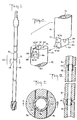
- Figure 1 is a plan pictorial representation showing a surgical reamer in which three coupling devices of an embodiment of the invention are shown. Full details of all parts of the devices are not shown in Figure 1 but are described below.
- Figure 2 is a plan pictorial representation showing an embodiment of a dovetail connection into which a tubing of flexible material is to be inserted.
- Figure 3 is a plan view of the male portion of the dovetail shown at the top of Figure 2, with dotted lines indicating where an insert made of plastic is located therein but protrudes partially therefrom outwardly in a radial direction.
- Figure 4 is a bottom view of Figure 3 (taken along the line 4-4) showing the bore of diameter d in the male portion of the dovetail and the counterbore of slightly larger diameter d1, in which a plastic insert is shown positioned.
- Figure 5 is a plan view of the female (bottom) portion of the dovetail in Figure 2, which has a bore and a counterbore located therein into which the plastic insert can protrude when the male and female portions mate together.
- Figure 6 is a top view of the female portion of the device shown in Figure 5. No plastic is in the female portion here.
- Figure 7 is a cross-sectional view of the device of Figure 1 taken along the line 7-7 at the smallest width of the male dovetail portion in the direction indicated, showing the plastic insert located substantially within the bore in the male portion but protruding therefrom outwardly in a radial direction into the female portion.
- This figure is a cross-sectional view of Figures 4 and 6 together.
- Figure 8 is a view in cross-section taken along the line 8-8 in Figure 7 showing the mating male and female portions of the dovetail, together with the wedging portion of flexible material located substantially within the bore of the male portion but protruding in a radial direction out of the male portion of the dovetail and into the counterbore located within the female portion of the dovetail in a preferred embodiment of the invention. Tolerances between the mating dovetail portions are not shown to be close.
- Figure 9 is a view in cross-section showing multiples of the embodiment of the device of the invention that was shown in Figure 8.
- an embodiment of the coupling device of the invention referred to generally as 10 is used in a reamer having multiple segments joined together by dovetail connections, especially a removable cutting head connected to a shaft by such a coupling device.
- a preferred coupling device of the invention comprises a male dovetail portion, the mating female dovetail portion, and a wedging portion made of a flexible material (not shown in detail in Figure 1 but described hereinafter).
- dovetail male portion 12 is shown separated from dovetail female portion 14.
- Dovetail male portion 12 is an integral part of first part 16 of the multiple component device which (in this embodiment) is in the form of a cylinder; and dovetail female portion 14 is an integral part of second part 18 of the multiple component device which (in this embodiment) is also in the form of a cylinder.
- Dovetail male portion 12 has a height h 19, which is the perpendicular distance between the outer end 20 and inner end 22 of dovetail male portion 12.
- the width of the dovetail at end 20 (which is the widest part of the male part of the dovetail) is w 24.
- the width of the male part of the dovetail at end 22 (which is the narrowest part of the dovetail) is w' 26.
- a hole or recess 28 located within dovetail male portion 12 is a hole or recess 28 which when viewed in a direction perpendicular thereto appears to be substantially triangular-shaped, with curved corners on the triangle.
- This recess 28 is formed on each side 30 of male dovetail portion 12 at the intersection of each side 30 with the counterbore 29 (not shown in Figure 2) located within dovetail male portion 12.
- First bore 31 in first part 16 has a diameter somewhat smaller than counterbore 29.
- dovetail female portion 14 also appears to be substantially triangular-shaped when viewed in a direction substantially perpendicular to the surface of side 34 of dovetail female portion 14. As can be seen in Figure 2, the upper boundary of each of recesses 32 is an arc of a circle.
- Dovetail female portion 14 has an inner end 38. The perpendicular distance h' 39 between outer end 36 of dovetail female portion 14 and inner end 38 of dovetail female portion 14 is preferably slightly larger than h 19, described above.
- recess 40 (which is the space within dovetail female portion 14 into which dovetail male portion 12 fits) has a largest width w1 42 (at or near end 38) which is slightly larger than width w 24 described above.
- Recess 40 at outer end 36 of dovetail female portion 14 has a width w1' 44, which is slightly larger than w' 26 described above.
- Recess 32 is a portion of the counterbore 46 located within female dovetail portion 14 and counterbore 46 has a diameter somewhat larger than the bore 50 in second part 18.
- dovetail male portion 12 (which is an integral part of first part 16) is shown, with first bore 31 and counterbore 29 shown in dotted lines. Also shown is a portion 52 of flexible material which protrudes outwardly in a radial direction through recess 28. Portion 52 of flexible material is a portion of flexible tubing 54, the major portion of which is located within counterbore 29, the tubing having an inner diameter which is approximately equal to the diameter d, of first bore 31.
- female portion 14 of the dovetail is shown with second bore 50 and second counterbore 46 located therein.
- Inner end 38 and outer end 36 are also shown, together with h'39, w1 42, w'1 44, and recess 40.
- second bore 50 and second counterbore 46 in female portion 14 are shown, as well as end 36 of female portion 14. End 38 is also shown. Bore 50 and counterbore 46 are located at different levels within second part 18, as shown clearly in Figure 5.
- flexible tubing 54 is shown. Bore 50 is also shown, together with counterbore 46. Flexible tubing 54 protrudes out of recesses 28 (shown in Figure 2) and protrudes into recess 32 within female portion 18 (shown in Figure 2.)
- dovetail male portion 12 and dovetail female portion 14 are shown in a mating position.
- First bore 31 in male portion 12 is shown aligned substantially coaxially with second bore 50 in female portion 14.
- Counterbore 29 in male portion 12 is shown, as is counterbore 46 in female portion 14.
- a portion 52 of flexible material is shown extending out of first bore 31 in male portion 12 and into recess 32 in female portion 14.
- Flexible tubing 54 is also shown.
- Portion 52 of flexible tubing 54 forms a wedging portion between male portion 12 and female portion 14.
- the use of the flexible material in the form of tubing and the use of the counterbores in the male and female portions keep the two mating parts centrally located and allow the flexible material to return to its natural shape so that a guidewire, if used, can pass through the bore of the device.
- the flexible material to be used in the device and method of the invention can be any suitable flexible material. Especially preferred is material which can be molded into the shape of tubing, for example, polypropylene or any other suitable material.
- the coupling device can be made by the following procedure. Any multiple-component device for use as a single device can be made with any suitable connection, for example a dovetail connection. If bores are located within the multiple components, a counterbore of a diameter slightly larger than the diameter of the bore will preferably be made in the male portion of the dovetail and another counterbore will be made in the female portion of the dovetail.
- the male portion counterbore should have a diameter which is slightly smaller than the largest width of the male dovetail portion and should also have a diameter which is slightly larger than the smallest width of the male dovetail portion, so as to provide a recess in the side of the male dovetail connection through which some of the flexible material can protrude. This protruding flexible material forms an interference between the mating parts of the dovetail.
Landscapes
- Health & Medical Sciences (AREA)
- Engineering & Computer Science (AREA)
- Mechanical Engineering (AREA)
- Surgery (AREA)
- Life Sciences & Earth Sciences (AREA)
- Molecular Biology (AREA)
- Veterinary Medicine (AREA)
- Nuclear Medicine, Radiotherapy & Molecular Imaging (AREA)
- Public Health (AREA)
- Biomedical Technology (AREA)
- Heart & Thoracic Surgery (AREA)
- Medical Informatics (AREA)
- General Health & Medical Sciences (AREA)
- Animal Behavior & Ethology (AREA)
- Dentistry (AREA)
- Oral & Maxillofacial Surgery (AREA)
- Orthopedic Medicine & Surgery (AREA)
- Snaps, Bayonet Connections, Set Pins, And Snap Rings (AREA)
- Surgical Instruments (AREA)
- Auxiliary Devices For And Details Of Packaging Control (AREA)
- Paper (AREA)
- Flexible Shafts (AREA)
- Making Paper Articles (AREA)
- Supplying Of Containers To The Packaging Station (AREA)
- Vehicle Body Suspensions (AREA)
- Air Bags (AREA)
Claims (9)
- Dispositif de raccord comprenant une première pièce (16) comportant une protubérance (12) qui en forme un prolongement et une seconde pièce (18) comportant un évidement (14) dans lequel ladite protubérance (12) peut se loger, caractérisé en ce que les première et seconde pièces comportent des contre-alésages respectifs (29, 46) qui sont sensiblement coaxiaux lorsque ladite protubérance est logée dans ledit évidement et un élément tubulaire de calage (54), en matière flexible, logé dans le contre-alésage (29) de la première pièce, déborde radialement vers l'extérieur de la protubérance et pénètre dans le contre-alésage (46) de la seconde pièce de manière à former un élément de calage provoquant un blocage entre les première et seconde pièces en empêchant lesdites pièces de se séparer d'elles-mêmes.
- Dispositif selon la revendication 1, caractérisé en ce que la majeure partie desdites première et seconde pièces est cylindrique et celles-ci comportent des alésages respectifs (31, 50) qui sont coaxiaux lorsqu'elles sont raccordées.
- Dispositif selon la revendication 1 ou 2, dans lequel ladite protubérance (12) et ledit évidement (14) sont des parties respectives mâle et femelle d'un raccord en queue d'aronde.
- Dispositif selon la revendication 3, dans lequel ledit contre-alésage (29) de la première pièce a une largeur qui est supérieure à la plus petite largeur, mais inférieure à la plus grande largeur de ladite protubérance (12).
- Dispositif selon la revendication 4, dans lequel ladite protubérance (12) a une hauteur qui est légèrement inférieure à la profondeur dudit contre-alésage (29) de la première pièce.
- Instrument de chirurgie comprenant au moins un dispositif de raccord selon l'une quelconque des revendications 1 à 5.
- Instrument selon la revendication 6, comprenant une tête d'alésoir qui est monobloc avec l'une desdites pièces.
- Procédé de raccord d'une première et d'une seconde pièce d'un dispositif à composants multiples dans lequel une protubérance (12) formant un prolongement de la première pièce s'ajuste dans un évidement (14) de la seconde pièce, caractérisé en ce que les première et seconde pièces comportent des contre-alésages respectifs (29, 46) qui sont sensiblement coaxiaux lorsque ladite protubérance est logée dans ledit évidement et un élément tubulaire de calage (54) en matière flexible, qui est logé dans le contre-alésage (29) de la première pièce, déborde radialement vers l'extérieur de la protubérance et pénètre dans le contre-alésage (46) de la seconde pièce de manière à former un élément de calage qui produit un blocage entre les première et seconde pièces en empêchant lesdites pièces de se séparer d'elles-mêmes.
- Procédé selon la revendication 8, dans lequel lesdites pièces font partie d'un instrument de chirurgie.
Applications Claiming Priority (2)
| Application Number | Priority Date | Filing Date | Title |
|---|---|---|---|
| US07/474,421 US5203595A (en) | 1990-02-02 | 1990-02-02 | Dovetail-type coupling device and method |
| US474421 | 1999-12-29 |
Publications (2)
| Publication Number | Publication Date |
|---|---|
| EP0444776A1 EP0444776A1 (fr) | 1991-09-04 |
| EP0444776B1 true EP0444776B1 (fr) | 1994-04-13 |
Family
ID=23883458
Family Applications (1)
| Application Number | Title | Priority Date | Filing Date |
|---|---|---|---|
| EP91300550A Expired - Lifetime EP0444776B1 (fr) | 1990-02-02 | 1991-01-24 | Dispositif et méthode de couplage |
Country Status (11)
| Country | Link |
|---|---|
| US (1) | US5203595A (fr) |
| EP (1) | EP0444776B1 (fr) |
| JP (1) | JPH0763471B2 (fr) |
| KR (2) | KR910021231A (fr) |
| AT (1) | ATE104187T1 (fr) |
| AU (1) | AU635106B2 (fr) |
| CA (1) | CA2035375C (fr) |
| DE (2) | DE69101657T2 (fr) |
| DK (1) | DK0444776T3 (fr) |
| ES (1) | ES2051078T3 (fr) |
| IE (1) | IE65061B1 (fr) |
Cited By (1)
| Publication number | Priority date | Publication date | Assignee | Title |
|---|---|---|---|---|
| CN106028978A (zh) * | 2014-02-17 | 2016-10-12 | T.A.G.医疗设备-农业合作社有限公司 | 柔性骨骼器具 |
Families Citing this family (54)
| Publication number | Priority date | Publication date | Assignee | Title |
|---|---|---|---|---|
| US5549613A (en) * | 1993-09-15 | 1996-08-27 | Mitek Surgical Products, Inc. | Modular surgical drill |
| EP0797406B1 (fr) * | 1994-12-12 | 1999-06-02 | Wim Fleischmann | Dispositif permettant de resserrer la peau |
| PL181761B1 (pl) * | 1995-12-09 | 2001-09-28 | Zierpka Eva Maria | Narzedzie wiertarskie kombinowane PL |
| US5979037A (en) * | 1997-02-06 | 1999-11-09 | Sony Corporation | Mounting assembly and method for locating and assembling parts with a tight press fit |
| US7150680B2 (en) | 1999-05-14 | 2006-12-19 | Precimed S.A. | Drive shaft coupling |
| US6811040B2 (en) * | 2001-07-16 | 2004-11-02 | Rohm And Haas Company | Wafer holding apparatus |
| DE60205934T2 (de) * | 2001-11-05 | 2006-06-08 | Precimed S.A. | Schneideinsatz-Antriebswelle Verbindung |
| US6949101B2 (en) * | 2002-03-29 | 2005-09-27 | Depuy Orthopaedics, Inc. | Medical instrument for milling a curved path in bone and procedure |
| US20040044346A1 (en) * | 2002-09-03 | 2004-03-04 | Boury Harb N. | Surgical tool with disposable/removable cutting tip |
| US20040136779A1 (en) * | 2003-01-13 | 2004-07-15 | Vishal Bhaskar | Connector |
| US7833228B1 (en) | 2004-01-05 | 2010-11-16 | Biomet Manufacturing Corp. | Method and instrumentation for performing minimally invasive hip arthroplasty |
| DE102007008837A1 (de) | 2007-02-23 | 2008-08-28 | Esa Eppinger Gmbh | Kupplungseinrichtung für Werkzeughalter oder Werkstückspanneinrichtungen |
| DE102007028429A1 (de) * | 2007-06-20 | 2008-12-24 | Krones Ag | Vorrichtung zum Verschließen von Behältern mit Schraubverschlüssen |
| US20100239380A1 (en) * | 2007-07-31 | 2010-09-23 | Stryker Trauma Gmbh | Carbon shafted reaming device |
| US8702709B2 (en) * | 2007-09-14 | 2014-04-22 | Said G. Osman | Intervertebral disc reamer |
| US8911474B2 (en) * | 2009-07-16 | 2014-12-16 | Howmedica Osteonics Corp. | Suture anchor implantation instrumentation system |
| CA2812775C (fr) | 2009-08-20 | 2015-09-29 | Howmedica Osteonics Corp. | Instrumentation souple, necessaire et methode applicables au ligament croise anterieur du genou |
| CH702093A1 (fr) * | 2009-10-28 | 2011-04-29 | Chirmat Sarl | Arbre d'entraînement pour alésoir chirurgical. |
| NL2003834C2 (en) * | 2009-11-19 | 2011-05-23 | A V Custom Style B V | Multipart quick-change and plug eject arbor for a hole saw. |
| US20110236853A1 (en) * | 2010-03-25 | 2011-09-29 | Klad Corporation | Dental drill extension |
| ES2380566T3 (es) * | 2010-03-31 | 2012-05-16 | Stryker Trauma Gmbh | Conexión entre vástago de fibras de carbono (CFK) y parte metálica mediante envoltura |
| ATE543447T1 (de) | 2010-03-31 | 2012-02-15 | Stryker Trauma Gmbh | Weitungsvorrichtung mit cfk-schaft und geformten schnittstellenelement |
| US8757667B2 (en) | 2010-07-16 | 2014-06-24 | Ipex Technologies Inc. | Adapters and connector assemblies for flow managing apparatuses |
| CA2714675C (fr) * | 2010-07-16 | 2017-05-09 | Ipex Technologies Inc. | Ensembles de connecteurs pour dispositifs limiteurs de debit |
| US8292150B2 (en) | 2010-11-02 | 2012-10-23 | Tyco Healthcare Group Lp | Adapter for powered surgical devices |
| US9795398B2 (en) | 2011-04-13 | 2017-10-24 | Howmedica Osteonics Corp. | Flexible ACL instrumentation, kit and method |
| KR101306773B1 (ko) * | 2011-10-14 | 2013-09-10 | (주)예스툴 | 절삭 공구 |
| US9445803B2 (en) | 2011-11-23 | 2016-09-20 | Howmedica Osteonics Corp. | Filamentary suture anchor |
| KR101276319B1 (ko) * | 2011-12-08 | 2013-06-18 | (주)예스툴 | 절삭 공구 |
| US9757536B2 (en) * | 2012-07-17 | 2017-09-12 | Novartis Ag | Soft tip cannula |
| US8821494B2 (en) | 2012-08-03 | 2014-09-02 | Howmedica Osteonics Corp. | Surgical instruments and methods of use |
| US9078740B2 (en) | 2013-01-21 | 2015-07-14 | Howmedica Osteonics Corp. | Instrumentation and method for positioning and securing a graft |
| US9554918B2 (en) * | 2013-03-01 | 2017-01-31 | Globus Medical, Inc. | Articulating expandable intervertebral implant |
| US9402620B2 (en) | 2013-03-04 | 2016-08-02 | Howmedica Osteonics Corp. | Knotless filamentary fixation devices, assemblies and systems and methods of assembly and use |
| US9788826B2 (en) | 2013-03-11 | 2017-10-17 | Howmedica Osteonics Corp. | Filamentary fixation device and assembly and method of assembly, manufacture and use |
| US9463013B2 (en) | 2013-03-13 | 2016-10-11 | Stryker Corporation | Adjustable continuous filament structure and method of manufacture and use |
| WO2014176270A1 (fr) | 2013-04-22 | 2014-10-30 | Pivot Medical, Inc. | Méthode et appareil de fixation d'un tissu à l'os |
| US10610211B2 (en) | 2013-12-12 | 2020-04-07 | Howmedica Osteonics Corp. | Filament engagement system and methods of use |
| US9986992B2 (en) | 2014-10-28 | 2018-06-05 | Stryker Corporation | Suture anchor and associated methods of use |
| US10568616B2 (en) | 2014-12-17 | 2020-02-25 | Howmedica Osteonics Corp. | Instruments and methods of soft tissue fixation |
| CN104688296B (zh) * | 2015-03-18 | 2018-02-02 | 马克 | 一种定向蛇形穿刺骨锥 |
| CN104985570B (zh) * | 2015-07-27 | 2016-09-07 | 陈志波 | 组合式工具 |
| US20170184209A1 (en) * | 2015-12-23 | 2017-06-29 | Spx Flow, Inc. | Hydraulic connection having a flexible port mouth and method for connecting same |
| JP7316788B2 (ja) | 2016-01-17 | 2023-07-28 | ティー.エー.ジー. メディカル デヴァイシス-アグリカルチャー コーポラティヴ リミテッド | 可撓性骨ツール |
| KR101678458B1 (ko) * | 2016-04-21 | 2016-12-06 | 주식회사 큐젠몰텍 | 절삭공구에 대한 미끄럼방지 및 수평정렬이 용이한 절삭공구 연결대 |
| US10836028B2 (en) * | 2016-07-10 | 2020-11-17 | Herbavore LLC | Interchangeable toollessly releasable handles for hand tools and methods of using the same |
| USD902405S1 (en) | 2018-02-22 | 2020-11-17 | Stryker Corporation | Self-punching bone anchor inserter |
| US11013520B2 (en) * | 2018-10-15 | 2021-05-25 | Avalign Technologies, Inc. | Reamer shaft extension assembly |
| CN111558911B (zh) * | 2020-05-21 | 2021-06-22 | 倪旭军 | 一种多空间环境使用基于螺纹防滑定位的十字螺丝刀 |
| US12117026B2 (en) * | 2020-11-06 | 2024-10-15 | Guangzhou Aquila Precise Tools Limited | Elastic connecting element, processing method thereof and flexible drill including elastic connecting element |
| US11761490B2 (en) * | 2021-02-26 | 2023-09-19 | Nissan North America, Inc. | Drive train connector assembly |
| US20230130904A1 (en) * | 2021-10-21 | 2023-04-27 | Xiaoqiang LU | Hula hoop unit sections and a hula hoop |
| US20260096824A1 (en) * | 2022-10-13 | 2026-04-09 | Wright Medical Technology, Inc. | Bone Material Harvesting Device Having Radially Expandable And Retractable Shaft |
| WO2025038329A1 (fr) * | 2023-08-11 | 2025-02-20 | Smith & Nephew, Inc. | Alésoir chirurgical |
Family Cites Families (14)
| Publication number | Priority date | Publication date | Assignee | Title |
|---|---|---|---|---|
| US210923A (en) * | 1878-12-17 | Improvement in hose-couplings | ||
| NL48313C (fr) * | ||||
| US1557743A (en) * | 1923-06-30 | 1925-10-20 | Terrill Albert | Steel bit for rock drills |
| US2717146A (en) * | 1953-04-09 | 1955-09-06 | John A Zublin | Heavy duty flexible drill pipe |
| US2985469A (en) * | 1957-09-09 | 1961-05-23 | Phillips Petroleum Co | Snap-fit plastic pipe joint |
| US3588149A (en) * | 1969-08-13 | 1971-06-28 | Amp Inc | Vacuum or pressure coupling devices |
| GB1468866A (fr) * | 1974-08-15 | 1977-03-30 | ||
| US4492226A (en) * | 1979-10-10 | 1985-01-08 | Vsesojuzny Nauchno-Issledovatelsky I Ispytatelny Institut Meditsinskoi Tekhniki | Device for uniting bone fragments |
| AT366254B (de) * | 1979-12-14 | 1982-03-25 | Ender Josef | Instrumentarium zur reposition und fixation von per- und subtrochanteren frakturen sowie einen teil dieses instrumentariums bildendes einsatzstueck |
| FR2560804A1 (fr) * | 1984-03-06 | 1985-09-13 | Birambeau As | Procede de fixation de la lame d'un couteau et couteau ainsi realise |
| US4706659A (en) * | 1984-12-05 | 1987-11-17 | Regents Of The University Of Michigan | Flexible connecting shaft for intramedullary reamer |
| EP0217055B1 (fr) * | 1985-07-31 | 1991-01-09 | Kawasumi Laboratories, Inc. | Raccord pour réservoir de plasmaphérèse |
| JPS6450808U (fr) * | 1987-09-25 | 1989-03-29 | ||
| JPH01265953A (ja) * | 1988-04-15 | 1989-10-24 | Tatsuo Kanashige | 動物用骨折部位支持具 |
-
1990
- 1990-02-02 US US07/474,421 patent/US5203595A/en not_active Expired - Lifetime
-
1991
- 1991-01-24 AT AT91300550T patent/ATE104187T1/de active
- 1991-01-24 EP EP91300550A patent/EP0444776B1/fr not_active Expired - Lifetime
- 1991-01-24 DE DE69101657T patent/DE69101657T2/de not_active Expired - Lifetime
- 1991-01-24 ES ES91300550T patent/ES2051078T3/es not_active Expired - Lifetime
- 1991-01-24 DK DK91300550.0T patent/DK0444776T3/da active
- 1991-01-31 CA CA002035375A patent/CA2035375C/fr not_active Expired - Lifetime
- 1991-02-01 IE IE35691A patent/IE65061B1/en not_active IP Right Cessation
- 1991-02-01 AU AU70224/91A patent/AU635106B2/en not_active Expired
- 1991-02-01 JP JP3098400A patent/JPH0763471B2/ja not_active Expired - Fee Related
- 1991-02-01 KR KR1019910001730A patent/KR910021231A/ko not_active Withdrawn
- 1991-02-01 DE DE9101150U patent/DE9101150U1/de not_active Expired - Lifetime
-
1993
- 1993-11-16 KR KR2019930023980U patent/KR940000279Y1/ko not_active Expired - Fee Related
Cited By (1)
| Publication number | Priority date | Publication date | Assignee | Title |
|---|---|---|---|---|
| CN106028978A (zh) * | 2014-02-17 | 2016-10-12 | T.A.G.医疗设备-农业合作社有限公司 | 柔性骨骼器具 |
Also Published As
| Publication number | Publication date |
|---|---|
| KR910021231A (ko) | 1991-12-20 |
| DE9101150U1 (de) | 1991-05-29 |
| ES2051078T3 (es) | 1994-06-01 |
| DE69101657T2 (de) | 1994-07-28 |
| ATE104187T1 (de) | 1994-04-15 |
| AU7022491A (en) | 1991-08-08 |
| KR940000279Y1 (ko) | 1994-01-19 |
| AU635106B2 (en) | 1993-03-11 |
| JPH04227242A (ja) | 1992-08-17 |
| EP0444776A1 (fr) | 1991-09-04 |
| JPH0763471B2 (ja) | 1995-07-12 |
| IE65061B1 (en) | 1995-10-04 |
| US5203595A (en) | 1993-04-20 |
| IE910356A1 (en) | 1991-08-14 |
| CA2035375C (fr) | 1995-02-07 |
| DK0444776T3 (da) | 1994-05-16 |
| DE69101657D1 (de) | 1994-05-19 |
Similar Documents
| Publication | Publication Date | Title |
|---|---|---|
| EP0444776B1 (fr) | Dispositif et méthode de couplage | |
| KR102535536B1 (ko) | 어깨 임플란트 구성요소 | |
| EP0735843B1 (fr) | Ensemble implant dentaire a retroaction tactile de la sensation digitale | |
| CA2021148C (fr) | Mecanisme d'attache de produits chirurgicaux modulaires | |
| EP0248979B1 (fr) | Composant d'accouplement | |
| US5683359A (en) | Arthroscopic surgical instruments having suction capability | |
| EP0548485B1 (fr) | Ensemble pour alésoir chirurgical | |
| US7001391B2 (en) | Surgical instrument with rotary cutting member and quick release coupling arrangement | |
| CA2656939C (fr) | Fixation d'une rampe de tapis et procede associe | |
| US5658290A (en) | Assembly comprising reamer spindle and reamer for surgery | |
| US5649947A (en) | Surgical instrument | |
| US8221364B2 (en) | Trocar obturator | |
| CA1178445A (fr) | Organe d'assemblage | |
| EP0775501A1 (fr) | Dispositif d'accouplement femelle pour un équipement d'hémodialyse | |
| EP0171077A2 (fr) | Dispositif d'introduction d'un catheter | |
| US20130018401A1 (en) | Surgical tool system with quick release coupling assembly | |
| EP0709073A1 (fr) | Dispositif de fixation d'une prothèse | |
| US5842865A (en) | Self-tapping implant with multiple concave tapping channels | |
| WO1999065403A1 (fr) | Blocs scie imbriques pour os | |
| GB2230192A (en) | Prosthetic interpositional device/coupler | |
| CN110996811A (zh) | 连接构件和方法 | |
| NZ520447A (en) | Coupling device for instrument parts | |
| EP0966928B1 (fr) | Prothese d'articulation avec vis de montée | |
| US5628747A (en) | Device for removing cancellous bone | |
| EP1707137A1 (fr) | Assemblage d'un obturateur à deux pièces |
Legal Events
| Date | Code | Title | Description |
|---|---|---|---|
| PUAI | Public reference made under article 153(3) epc to a published international application that has entered the european phase |
Free format text: ORIGINAL CODE: 0009012 |
|
| 17P | Request for examination filed |
Effective date: 19910212 |
|
| AK | Designated contracting states |
Kind code of ref document: A1 Designated state(s): AT BE CH DE DK ES FR GB GR IT LI LU NL SE |
|
| RAP1 | Party data changed (applicant data changed or rights of an application transferred) |
Owner name: HOWMEDICA INC. |
|
| 17Q | First examination report despatched |
Effective date: 19930521 |
|
| GRAA | (expected) grant |
Free format text: ORIGINAL CODE: 0009210 |
|
| AK | Designated contracting states |
Kind code of ref document: B1 Designated state(s): AT BE CH DE DK ES FR GB GR IT LI LU NL SE |
|
| REF | Corresponds to: |
Ref document number: 104187 Country of ref document: AT Date of ref document: 19940415 Kind code of ref document: T |
|
| REG | Reference to a national code |
Ref country code: DK Ref legal event code: T3 |
|
| REF | Corresponds to: |
Ref document number: 69101657 Country of ref document: DE Date of ref document: 19940519 |
|
| ITF | It: translation for a ep patent filed | ||
| REG | Reference to a national code |
Ref country code: ES Ref legal event code: FG2A Ref document number: 2051078 Country of ref document: ES Kind code of ref document: T3 |
|
| ET | Fr: translation filed | ||
| REG | Reference to a national code |
Ref country code: GR Ref legal event code: FG4A Free format text: 3012032 |
|
| EAL | Se: european patent in force in sweden |
Ref document number: 91300550.0 |
|
| PLBE | No opposition filed within time limit |
Free format text: ORIGINAL CODE: 0009261 |
|
| STAA | Information on the status of an ep patent application or granted ep patent |
Free format text: STATUS: NO OPPOSITION FILED WITHIN TIME LIMIT |
|
| 26N | No opposition filed | ||
| PGFP | Annual fee paid to national office [announced via postgrant information from national office to epo] |
Ref country code: SE Payment date: 19981218 Year of fee payment: 9 |
|
| PGFP | Annual fee paid to national office [announced via postgrant information from national office to epo] |
Ref country code: DK Payment date: 19981221 Year of fee payment: 9 |
|
| PGFP | Annual fee paid to national office [announced via postgrant information from national office to epo] |
Ref country code: NL Payment date: 19981222 Year of fee payment: 9 |
|
| PGFP | Annual fee paid to national office [announced via postgrant information from national office to epo] |
Ref country code: GR Payment date: 19981230 Year of fee payment: 9 |
|
| PGFP | Annual fee paid to national office [announced via postgrant information from national office to epo] |
Ref country code: AT Payment date: 19990112 Year of fee payment: 9 |
|
| PGFP | Annual fee paid to national office [announced via postgrant information from national office to epo] |
Ref country code: BE Payment date: 19990118 Year of fee payment: 9 |
|
| PGFP | Annual fee paid to national office [announced via postgrant information from national office to epo] |
Ref country code: ES Payment date: 19990120 Year of fee payment: 9 |
|
| PGFP | Annual fee paid to national office [announced via postgrant information from national office to epo] |
Ref country code: CH Payment date: 19990210 Year of fee payment: 9 |
|
| PGFP | Annual fee paid to national office [announced via postgrant information from national office to epo] |
Ref country code: LU Payment date: 19990218 Year of fee payment: 9 |
|
| REG | Reference to a national code |
Ref country code: CH Ref legal event code: PFA Free format text: HOWMEDICA, INC. TRANSFER- MTG DIVESTITURES INC. Ref country code: CH Ref legal event code: PUE Owner name: MTG DIVESTITURES INC. TRANSFER- STRYKER TECHNOLOGI |
|
| PG25 | Lapsed in a contracting state [announced via postgrant information from national office to epo] |
Ref country code: AT Free format text: LAPSE BECAUSE OF NON-PAYMENT OF DUE FEES Effective date: 20000124 Ref country code: DK Free format text: LAPSE BECAUSE OF NON-PAYMENT OF DUE FEES Effective date: 20000124 Ref country code: LU Free format text: LAPSE BECAUSE OF NON-PAYMENT OF DUE FEES Effective date: 20000124 |
|
| PG25 | Lapsed in a contracting state [announced via postgrant information from national office to epo] |
Ref country code: SE Free format text: LAPSE BECAUSE OF NON-PAYMENT OF DUE FEES Effective date: 20000125 Ref country code: ES Free format text: LAPSE BECAUSE OF NON-PAYMENT OF DUE FEES Effective date: 20000125 |
|
| PG25 | Lapsed in a contracting state [announced via postgrant information from national office to epo] |
Ref country code: BE Free format text: LAPSE BECAUSE OF NON-PAYMENT OF DUE FEES Effective date: 20000131 Ref country code: LI Free format text: LAPSE BECAUSE OF NON-PAYMENT OF DUE FEES Effective date: 20000131 Ref country code: GR Free format text: LAPSE BECAUSE OF NON-PAYMENT OF DUE FEES Effective date: 20000131 Ref country code: CH Free format text: LAPSE BECAUSE OF NON-PAYMENT OF DUE FEES Effective date: 20000131 |
|
| NLS | Nl: assignments of ep-patents |
Owner name: STRYKER TECHNOLOGIES CORPORATION |
|
| NLT1 | Nl: modifications of names registered in virtue of documents presented to the patent office pursuant to art. 16 a, paragraph 1 |
Owner name: MTG DIVESTITURES INC. |
|
| BERE | Be: lapsed |
Owner name: STRYKER TECHNOLOGIES CORP. Effective date: 20000131 |
|
| PG25 | Lapsed in a contracting state [announced via postgrant information from national office to epo] |
Ref country code: NL Free format text: LAPSE BECAUSE OF NON-PAYMENT OF DUE FEES Effective date: 20000801 |
|
| REG | Reference to a national code |
Ref country code: GB Ref legal event code: 732E |
|
| EUG | Se: european patent has lapsed |
Ref document number: 91300550.0 |
|
| REG | Reference to a national code |
Ref country code: CH Ref legal event code: PL |
|
| NLV4 | Nl: lapsed or anulled due to non-payment of the annual fee |
Effective date: 20000801 |
|
| REG | Reference to a national code |
Ref country code: DK Ref legal event code: EBP |
|
| REG | Reference to a national code |
Ref country code: FR Ref legal event code: TP Ref country code: FR Ref legal event code: CD |
|
| BECH | Be: change of holder |
Free format text: 20000201 *STRYKER TECHNOLOGIES CORP. |
|
| REG | Reference to a national code |
Ref country code: ES Ref legal event code: FD2A Effective date: 20011010 |
|
| REG | Reference to a national code |
Ref country code: GB Ref legal event code: IF02 |
|
| PG25 | Lapsed in a contracting state [announced via postgrant information from national office to epo] |
Ref country code: IT Free format text: LAPSE BECAUSE OF NON-PAYMENT OF DUE FEES Effective date: 20050124 |
|
| REG | Reference to a national code |
Ref country code: GB Ref legal event code: 732E |
|
| REG | Reference to a national code |
Ref country code: FR Ref legal event code: TP |
|
| PGFP | Annual fee paid to national office [announced via postgrant information from national office to epo] |
Ref country code: GB Payment date: 20091211 Year of fee payment: 20 |
|
| PGFP | Annual fee paid to national office [announced via postgrant information from national office to epo] |
Ref country code: FR Payment date: 20100125 Year of fee payment: 20 |
|
| PGFP | Annual fee paid to national office [announced via postgrant information from national office to epo] |
Ref country code: DE Payment date: 20100129 Year of fee payment: 20 |
|
| REG | Reference to a national code |
Ref country code: GB Ref legal event code: PE20 Expiry date: 20110123 |
|
| PG25 | Lapsed in a contracting state [announced via postgrant information from national office to epo] |
Ref country code: GB Free format text: LAPSE BECAUSE OF EXPIRATION OF PROTECTION Effective date: 20110123 |
|
| PG25 | Lapsed in a contracting state [announced via postgrant information from national office to epo] |
Ref country code: DE Free format text: LAPSE BECAUSE OF EXPIRATION OF PROTECTION Effective date: 20110124 |