EP0444823A2 - Multiple roll impregnator - Google Patents
Multiple roll impregnator Download PDFInfo
- Publication number
- EP0444823A2 EP0444823A2 EP91301391A EP91301391A EP0444823A2 EP 0444823 A2 EP0444823 A2 EP 0444823A2 EP 91301391 A EP91301391 A EP 91301391A EP 91301391 A EP91301391 A EP 91301391A EP 0444823 A2 EP0444823 A2 EP 0444823A2
- Authority
- EP
- European Patent Office
- Prior art keywords
- roll
- fabric
- rolls
- impregnator
- resin
- Prior art date
- Legal status (The legal status is an assumption and is not a legal conclusion. Google has not performed a legal analysis and makes no representation as to the accuracy of the status listed.)
- Ceased
Links
- 239000004744 fabric Substances 0.000 claims abstract description 101
- 229920005989 resin Polymers 0.000 claims abstract description 40
- 239000011347 resin Substances 0.000 claims abstract description 40
- 239000007788 liquid Substances 0.000 claims description 12
- 239000004745 nonwoven fabric Substances 0.000 claims description 3
- 239000002759 woven fabric Substances 0.000 claims description 3
- 238000000034 method Methods 0.000 abstract description 4
- 238000005470 impregnation Methods 0.000 abstract description 2
- 239000011152 fibreglass Substances 0.000 description 8
- 238000010586 diagram Methods 0.000 description 3
- 229920001225 polyester resin Polymers 0.000 description 3
- 239000004645 polyester resin Substances 0.000 description 3
- 239000000835 fiber Substances 0.000 description 2
- 230000007246 mechanism Effects 0.000 description 2
- 230000004048 modification Effects 0.000 description 2
- 238000012986 modification Methods 0.000 description 2
- 239000004677 Nylon Substances 0.000 description 1
- 230000004075 alteration Effects 0.000 description 1
- 230000005540 biological transmission Effects 0.000 description 1
- 230000000694 effects Effects 0.000 description 1
- 239000002783 friction material Substances 0.000 description 1
- 239000011521 glass Substances 0.000 description 1
- 229920001903 high density polyethylene Polymers 0.000 description 1
- 239000004700 high-density polyethylene Substances 0.000 description 1
- 239000000463 material Substances 0.000 description 1
- 229920001778 nylon Polymers 0.000 description 1
- 230000035515 penetration Effects 0.000 description 1
- 238000006467 substitution reaction Methods 0.000 description 1
Images


Classifications
-
- B—PERFORMING OPERATIONS; TRANSPORTING
- B29—WORKING OF PLASTICS; WORKING OF SUBSTANCES IN A PLASTIC STATE IN GENERAL
- B29B—PREPARATION OR PRETREATMENT OF THE MATERIAL TO BE SHAPED; MAKING GRANULES OR PREFORMS; RECOVERY OF PLASTICS OR OTHER CONSTITUENTS OF WASTE MATERIAL CONTAINING PLASTICS
- B29B15/00—Pretreatment of the material to be shaped, not covered by groups B29B7/00 - B29B13/00
- B29B15/08—Pretreatment of the material to be shaped, not covered by groups B29B7/00 - B29B13/00 of reinforcements or fillers
- B29B15/10—Coating or impregnating independently of the moulding or shaping step
- B29B15/12—Coating or impregnating independently of the moulding or shaping step of reinforcements of indefinite length
- B29B15/122—Coating or impregnating independently of the moulding or shaping step of reinforcements of indefinite length with a matrix in liquid form, e.g. as melt, solution or latex
-
- B—PERFORMING OPERATIONS; TRANSPORTING
- B05—SPRAYING OR ATOMISING IN GENERAL; APPLYING FLUENT MATERIALS TO SURFACES, IN GENERAL
- B05C—APPARATUS FOR APPLYING FLUENT MATERIALS TO SURFACES, IN GENERAL
- B05C3/00—Apparatus in which the work is brought into contact with a bulk quantity of liquid or other fluent material
- B05C3/18—Apparatus in which the work is brought into contact with a bulk quantity of liquid or other fluent material only one side of the work coming into contact with the liquid or other fluent material
Definitions
- the present invention relates to a fiberglass and resin-applicating apparatus, and more particularly to an apparatus for impregnating a fabric with a resin.
- Fiberglass fabrics woven or nonwoven are impregnated with a resin, such as a polyester resin, and thereafter laid on a mold.
- resin is applied to the fabric.
- Prior art impregnators apply the resin to the fabric in an amount in excess of that which the fabric will absorb.
- the fabric is then run between a pair of nip rolls to squeeze excess resin.
- air is trapped in the fabric. The trapped air must be rolled out by finned rolls or removed with squeegees after the fabric is laid onto a mold, a very laborious job.
- the present invention provides an apparatus for impregnating a strip of woven or nonwoven fabric with a viscous liquid such as a polyester resin, in a manner that virtually eliminates the possibility of entrapping air in the fabric.
- the apparatus includes a means for holding a roll of fabric and a first roll means for receiving the fabric from the roll.
- the first roll means (preferably a pair of rolls) is employed to pull the fabric from the roll and meter the speed at which the fabric is fed to a second roll.
- the second roll receives the fabric from the first roll means.
- a third roll positioned above the second roll receives fabric from the second roll after the fabric is wrapped partway around the second roll.
- a fourth roll positioned beside the second roll and below the third roll receives the fabric from the third roll after the fabric is wrapped partway around the third roll.
- the second and fourth rolls intimately engage opposite sides of the fabric. After the fabric leaves the fourth roll, it travels between a fifth roll and the fourth roll.
- the fifth roll is positioned on the top side of the fourth roll opposite from the second roll.
- Means are provided for rotatng at least the first roll means and the fourth roll.
- Means are also provided for introducing a viscous liquid into the space between the fabric and the fourth roll so that the liquid is applied to only one side of the fabric as it travels upwardly from the second roll toward the third roll. Excess liquid is applied to the one side of the fabric.
- That liquid is pressed with a radial force into and through the fabric as the fabric passes over the third roll. Excess resin is then squeezed from the fabric as it travels between the fifth and fourth rolls. In this manner, the fabric is impregnated with resin and is virtually free of entrapped air, primarily because the liquid is applied to the fabric from only one side and forced through the fabric by the third roll.
- the rollout apparatus constructed in accordance with the present invention is illustrated connected to a fiberglass mat impregnating and lay-down assembly generally designated 12.
- the assembly 12 includes the rollout apparatus, an impregnator 14, an operator's stand 16, and an overhead crane assembly, generally designated 18, for translating the impregnator and rollout device in two directions so that successive lengths of impregnated mat can be laid laterally across a mold 20.
- the overhead crane assembly 18 is constructed in a conventional manner and includes a pair of longitudinal rails (only one of which, 21, can be seen in FIGURE 1) supported by framework 22 only partially shown.
- a pair of I-beams 24 and 26 depend from two sets of trucks (only one set of which, 28 and 30, can be seen in FIGURE 1) riding on the longitudinal rails.
- the support frame 31 for the impregnator and rollout device is suspended from two sets of trucks (only one set of which, 32 and 34, can be seen in FIGURE 1). These trucks ride on the upper surface of the lower cross member of the I-beams 24 and 26.
- the impregnator 14 is suspended below the support frame 31 by appropriate depending structure 36.
- the impregnator carries a roll 38 of fiberglass wet, mat, roving, or other woven or nonwoven fabric, which is impregnated with polyester resin or other suitable resin by the impregnator 14.
- a sheet of resin impregnated mat 40 drops from the impregnator 14 and engages the upper surface of the mold 20 as the assembly 12 is translated in the direction of arrow 42 along the entire length of the mold 20.
- a rollout apparatus 10 carries sets of roller 50 and 52 that are mounted on oscillating carriages 54 and 56.
- a drive assembly 58 is provided to reciprocate the carriages 54 and 56 in an opposite direction to cause the rollers to traverse the impregnated mat in opposite directions as the assembly 12 traverses the length of the mold 20. In this manner, the impregnated mat is properly consolidated against the mold.
- a mechanism is provided to retract the rollers 52 upwardly from the mold. The glass mat is severed and the assembly is rotated or returned to the other end of the mold, indexed transversely across the mold, and a second mat is laid down and rolled out by the rollout apparatus 10 of the present invention. This procedure is repeated until the laminate is completed.
- the present invention has been described in relation to laying down successive lengths of fiberglass fabric across a flat mold, it is to be understood that a variety of mold shapes can be employed successfully with the present invention.
- the apparatus of the present invention can be utilized to lay successive lengths of impregnated fiberglass fabric across a curved mold such as a boat hull.
- the impregnator 14 includes a pair of box frames 60 and 62 on each side, joined by upper forward cross member 64, lower forward cross member 66, and lower rearward cross member 68.
- Side panels 70 and 72 are mounted on the outsides of the box frames 60 and 62.
- the bearings for all of the rollers in the impregnator are mounted on the side panels 70 and 72.
- a pair of uprights 74 and 76 extend upwardly from the upper end of the box frames.
- the uprights carry a pair of upwardly opening cradles 78 and 80.
- a roll 84 of fiberglass woven or unwoven fabric, is supported on a rod 82, which in turn rests in the cradles 80 and 78.
- a strip 86 of the fabric extends downwardly from the forward side of the roll 84 into a pair of nip rolls 90 and 92.
- the nip rolls are mounted in appropriate bearings on the side panels 70 and 72 at a location toward the upper rearward portion of the box frames 60 and 62.
- Nip rolls 90 and 92 serve to draw fabric from the roll 84 and control the descent of the fabric toward the first impregnator roll 94.
- the nip rolls 90 and 92 are mounted for rotation about horizontal axes that are parallel to each other.
- the surfaces of the nip rolls are composed of rubber or other high-friction material so that a good grip on the fabric is achieved. All of the remaining rolls in the apparatus are also mounted for rotation about horizontal axes that are parallel to each other.
- the first impregnator roll 94 is larger than the nip rolls and is mounted near the bottom rearward portion of the box frames.
- the fabric strip 86 extends around the rearward side of the roll 94 and up the forward side in a substantially vertical direction.
- the strip 86 then extends around a pressure roll 96, which is mounted above and slightly forwardly of the first impregnator roll 94, such that the fabric strip running between the roll 94 and 96 is substantially vertically oriented.
- the fabric strip then runs over the top of the pressure roll 96, around the front of the roll and back down toward the upper central portion of a second impregnator roll 98, which is mounted immediately forwardly of the first impregnator roll 94.
- An idler roll 100 is mounted above and slightly forwardly of the axis of the second impregnator roll 98.
- Fabric strip 86 extends downwardly from the pressure roll 96, around the rearward side of the idler roll 100 and between the idler roll and the second impregnator roll 98. Thereafter the fabric strip drops downwardly from the forward side of the impregnator roll 98 and is laid on a mold.
- Resin is supplied through a resin supply tube 110 extending through the right side panel 72 at a location above the impregnator roll 98, and between the first impregnator roll 94 and the idler roll 100.
- the resin is supplied to a pool 112 on the forward side of the fabric, which extends upwardly from the first impregnator roll 94 to the pressure roll 96.
- resin is supplied to only one side of the fabric so that air is not trapped within the fabric as is the case with prior art impregnators where resin is supplied from both sides of the fabric. Excess resin is supplied so that a layer of resin is still present on the forward side of the fabric strip 86 as it begins to engage the pressure roll 96.
- the shaft 120 of the idler roll 100 is mounted on a pair of horizontal arms 122 and 124.
- the arms extend forwardly from the shaft 120 and are mounted respectively to the side panels 72 and 70 via appropriate pivot pins.
- Conventional micrometer jackscrew adjusting mechanisms 124 and 126 are coupled between the central portions of the arms 122 and 124 and the side panels 70 and 72, allowing the arms to be selectively raised and lowered, thus raising and lowering the idler roll 100. In this manner, the distance of the surface of the idler roll 100 from the surface of the second impregnator roll 98 can be adjusted so that the exact amount of resin left in the fabric can be metered as desired.
- a pneumatically powered motor 130 is mounted on the left side of the impregnator.
- the motor powers a transmission 132, which in turn rotates the shaft 134 of the second impregnator roll 98.
- a sprocket 136 is attached to the opposite end of the shaft 134.
- a second sprocket 138 is affixed to the shaft 140 of the rearmost nip roll 90.
- An endless chain 142 couples the sprockets 136 and 138 so that the nip roll 90 is also driven.
- a pair of gears 144 are mounted respectively to the shafts 140 and 146 of the nip rolls 90 and 92 so that the nip rolls are simultaneously driven as well.
- the sprockets 136 and 138 and the gears 144 are sized such that the surface speeds of the nip rolls are matched to the surface speeds of the first impregnator roll 94.
- Rolls 94, 96 and 100 in the preferred embodiment are idlers, thus being driven by the fabric passing past the rolls.
- an optional seventh roll 150 is positioned above the first impregnator roll 94 and spaced away from the second impregnator roll 98.
- the seventh roll 150 presses the fabric against the first impregnator roll so that the fabric has a longer contact time with the puddle of resin between the first and second impregnator rolls.
- the fabric then extends upwardly from the seventh roll 150 to the pressure roll 96 and thence, as in the prior embodiments, to the idler 100 and second impregnator roll 98.
- roll 150 can be finned to allow more resin to remain on the inside of the strip 86 as it traverses toward the pressure roll 96.
- a pair of pinch rolls 152 and 154 are positioned below the pressure roll 96 and above the idler 100 and second impregnator roll 98. Fabric leaving the pressure roll traverses between the pinch rolls 152 and 154 and thence to the idler roll 100.
- an additional resin input port 156 can be provided above pinch roll 152 so that a pool of resin 158 is formed between the fabric and the inside pinch roll 152, which is positioned between the fabric going toward and leaving the pressure roll 96. Excess resin can drip over the inside of the inside pinch roll 152 and down into the original resin pool 112.
- inside pinch roll 152 can be finned so that additional resin is allowed to accumulate on the inside surface of the fabric as it extends down toward idler roll 100.
- FIGURE 8 illustrates a modification of the eight-roll system shown in FIGURE 7.
- a ninth roll 162 is positioned between the pinch rolls 152 and 154 and the idler roll 100.
- the ninth roll 162 is positioned on the inside of the fabric, that is, between the fabric extending from the impregnator rolls 94 and 98 toward the pressure roll 96 and the fabric leaving the pinch rolls 152 and 154 and extending toward the idler roll 100.
- the ninth roll 162 is offset outwardly so that the fabric traverses approximately 160° around ninth roll 162.
- the ninth roll causes additional flexure of the fiber and opens up the interstices between the fibers to cause better penetration of the resin into a heavy fabric or fabric laminate. If desired, the seventh, eighth, and ninth rolls can be driven to assure that they will turn as the fabric traverses them.
Landscapes
- Engineering & Computer Science (AREA)
- Mechanical Engineering (AREA)
- Reinforced Plastic Materials (AREA)
- Treatment Of Fiber Materials (AREA)
Abstract
Description
- The present invention relates to a fiberglass and resin-applicating apparatus, and more particularly to an apparatus for impregnating a fabric with a resin.
- Fiberglass fabrics woven or nonwoven, are impregnated with a resin, such as a polyester resin, and thereafter laid on a mold. During the impregnation process, resin is applied to the fabric. Prior art impregnators apply the resin to the fabric in an amount in excess of that which the fabric will absorb. The fabric is then run between a pair of nip rolls to squeeze excess resin. During this process, air is trapped in the fabric. The trapped air must be rolled out by finned rolls or removed with squeegees after the fabric is laid onto a mold, a very laborious job.
- The present invention provides an apparatus for impregnating a strip of woven or nonwoven fabric with a viscous liquid such as a polyester resin, in a manner that virtually eliminates the possibility of entrapping air in the fabric. The apparatus includes a means for holding a roll of fabric and a first roll means for receiving the fabric from the roll. Normally, the first roll means (preferably a pair of rolls) is employed to pull the fabric from the roll and meter the speed at which the fabric is fed to a second roll. The second roll receives the fabric from the first roll means. A third roll positioned above the second roll receives fabric from the second roll after the fabric is wrapped partway around the second roll. A fourth roll positioned beside the second roll and below the third roll receives the fabric from the third roll after the fabric is wrapped partway around the third roll. The second and fourth rolls intimately engage opposite sides of the fabric. After the fabric leaves the fourth roll, it travels between a fifth roll and the fourth roll. The fifth roll is positioned on the top side of the fourth roll opposite from the second roll. Means are provided for rotatng at least the first roll means and the fourth roll. Means are also provided for introducing a viscous liquid into the space between the fabric and the fourth roll so that the liquid is applied to only one side of the fabric as it travels upwardly from the second roll toward the third roll. Excess liquid is applied to the one side of the fabric. That liquid is pressed with a radial force into and through the fabric as the fabric passes over the third roll. Excess resin is then squeezed from the fabric as it travels between the fifth and fourth rolls. In this manner, the fabric is impregnated with resin and is virtually free of entrapped air, primarily because the liquid is applied to the fabric from only one side and forced through the fabric by the third roll.
- A better understanding of the present invention can be derived by reading the ensuing specification in conjunction with the accompanying drawings wherein:
- FIGURE 1 is a side elevation view of a six roll impregnator and a rollout apparatus forming part of a fiberglass resin lay-down system;
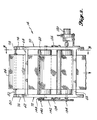
- FIGURE 2 is an enlarged front elevation view of the six roll impregnator constructed in accordance with the present invention;
- FIGURE 3 is a partial cross-sectional view of the apparatus taken along A section line 3-3 of FIGURE 2;
- FIGURE 4 is a left side elevation view of the apparatus shown in FIGURE 2;
- FIGURE 5 is a right side elevation view of the impregnator shown in FIGURE 2;
- FIGURE 6 is a schematic diagram of an alternate embodiment of the present invention employing seven rolls;
- FIGURE 7 is a schematic diagram of an alternate embodiment of the present invention employing eight rolls; and
- FIGURE 8 is a schematic diagram of an alternate embodiment of the present invention employing nine rolls.
- Referring first to FIGURE 1, the rollout apparatus constructed in accordance with the present invention, generally designated 10, is illustrated connected to a fiberglass mat impregnating and lay-down assembly generally designated 12. The
assembly 12 includes the rollout apparatus, animpregnator 14, an operator's stand 16, and an overhead crane assembly, generally designated 18, for translating the impregnator and rollout device in two directions so that successive lengths of impregnated mat can be laid laterally across amold 20. Theoverhead crane assembly 18 is constructed in a conventional manner and includes a pair of longitudinal rails (only one of which, 21, can be seen in FIGURE 1) supported byframework 22 only partially shown. A pair of I-beams 24 and 26 depend from two sets of trucks (only one set of which, 28 and 30, can be seen in FIGURE 1) riding on the longitudinal rails. Thesupport frame 31 for the impregnator and rollout device is suspended from two sets of trucks (only one set of which, 32 and 34, can be seen in FIGURE 1). These trucks ride on the upper surface of the lower cross member of the I-beams 24 and 26. - The
impregnator 14 is suspended below thesupport frame 31 by appropriate dependingstructure 36. The impregnator carries aroll 38 of fiberglass wet, mat, roving, or other woven or nonwoven fabric, which is impregnated with polyester resin or other suitable resin by theimpregnator 14. A sheet of resin impregnatedmat 40 drops from theimpregnator 14 and engages the upper surface of themold 20 as theassembly 12 is translated in the direction ofarrow 42 along the entire length of themold 20. Arollout apparatus 10 carries sets ofroller carriages drive assembly 58 is provided to reciprocate thecarriages assembly 12 traverses the length of themold 20. In this manner, the impregnated mat is properly consolidated against the mold. When theassembly 12 reaches the end of the mold, a mechanism is provided to retract therollers 52 upwardly from the mold. The glass mat is severed and the assembly is rotated or returned to the other end of the mold, indexed transversely across the mold, and a second mat is laid down and rolled out by therollout apparatus 10 of the present invention. This procedure is repeated until the laminate is completed. - While the present invention has been described in relation to laying down successive lengths of fiberglass fabric across a flat mold, it is to be understood that a variety of mold shapes can be employed successfully with the present invention. For example, with a modification to the mounting assembly for the impregnator and rollout apparatus so that it can also be moved vertically, the apparatus of the present invention can be utilized to lay successive lengths of impregnated fiberglass fabric across a curved mold such as a boat hull.
- Referring now to FIGURES 2 and 3, the
impregnator 14 includes a pair ofbox frames forward cross member 64, lowerforward cross member 66, and lower rearwardcross member 68.Side panels box frames side panels uprights cradles roll 84 of fiberglass woven or unwoven fabric, is supported on arod 82, which in turn rests in thecradles strip 86 of the fabric extends downwardly from the forward side of theroll 84 into a pair ofnip rolls side panels box frames Nip rolls roll 84 and control the descent of the fabric toward thefirst impregnator roll 94. Thenip rolls - The
first impregnator roll 94 is larger than the nip rolls and is mounted near the bottom rearward portion of the box frames. Thefabric strip 86 extends around the rearward side of theroll 94 and up the forward side in a substantially vertical direction. Thestrip 86 then extends around apressure roll 96, which is mounted above and slightly forwardly of thefirst impregnator roll 94, such that the fabric strip running between theroll pressure roll 96, around the front of the roll and back down toward the upper central portion of asecond impregnator roll 98, which is mounted immediately forwardly of thefirst impregnator roll 94. Anidler roll 100 is mounted above and slightly forwardly of the axis of thesecond impregnator roll 98.Fabric strip 86 extends downwardly from thepressure roll 96, around the rearward side of theidler roll 100 and between the idler roll and thesecond impregnator roll 98. Thereafter the fabric strip drops downwardly from the forward side of theimpregnator roll 98 and is laid on a mold. - Resin is supplied through a
resin supply tube 110 extending through theright side panel 72 at a location above theimpregnator roll 98, and between thefirst impregnator roll 94 and theidler roll 100. The resin is supplied to apool 112 on the forward side of the fabric, which extends upwardly from thefirst impregnator roll 94 to thepressure roll 96. In this manner, resin is supplied to only one side of the fabric so that air is not trapped within the fabric as is the case with prior art impregnators where resin is supplied from both sides of the fabric. Excess resin is supplied so that a layer of resin is still present on the forward side of thefabric strip 86 as it begins to engage thepressure roll 96. This excess resin is pressed radially outwardly through the fabric as the fabric traverses over the top of thepressure roll 96. Sufficient resin has been applied so that as the fabric strip leaves thepressure roll 96, excess resin is now present in thestrip 86 as it passes downwardly toward theidler roll 100. Excess resin is then pressed from the fabric as it passes between theimpregnator roll 98 and theidler roll 100. The excess resin is returned to theresin pool 112 on top of thesecond impregnator roll 98. Conventional side dams 114 (only one of which is shown in FIGURE 3) are provided on each side of the impregnator rolls 94 and 98 to prevent resin from dropping from the end of the rolls. These side dams are typically made of a material having a low coefficient of friction, such as nylon or high-density polyethylene. - Referring now to FIGURES 3 and 5, the
shaft 120 of theidler roll 100 is mounted on a pair ofhorizontal arms shaft 120 and are mounted respectively to theside panels jackscrew adjusting mechanisms arms side panels idler roll 100. In this manner, the distance of the surface of theidler roll 100 from the surface of thesecond impregnator roll 98 can be adjusted so that the exact amount of resin left in the fabric can be metered as desired. - Still referring to FIGURES 3, 4 and 5, a pneumatically powered
motor 130 is mounted on the left side of the impregnator. The motor powers atransmission 132, which in turn rotates theshaft 134 of thesecond impregnator roll 98. Asprocket 136 is attached to the opposite end of theshaft 134. Asecond sprocket 138 is affixed to theshaft 140 of the rearmost niproll 90. Anendless chain 142 couples thesprockets nip roll 90 is also driven. A pair ofgears 144 are mounted respectively to theshafts sprockets gears 144 are sized such that the surface speeds of the nip rolls are matched to the surface speeds of thefirst impregnator roll 94.Rolls - In some applications where heavier fabrics, or a plurality of fabric laminates are employed, additional rolls may be optionally employed to achieve better resin saturation in the fabric. Referring to FIGURE 6, an optional
seventh roll 150 is positioned above thefirst impregnator roll 94 and spaced away from thesecond impregnator roll 98. Theseventh roll 150 presses the fabric against the first impregnator roll so that the fabric has a longer contact time with the puddle of resin between the first and second impregnator rolls. The fabric then extends upwardly from theseventh roll 150 to thepressure roll 96 and thence, as in the prior embodiments, to the idler 100 andsecond impregnator roll 98. Optionally, roll 150 can be finned to allow more resin to remain on the inside of thestrip 86 as it traverses toward thepressure roll 96. - Referring to FIGURE 7, an eight-roll option is illustrated. In this optional arrangement, a pair of pinch rolls 152 and 154 are positioned below the
pressure roll 96 and above the idler 100 andsecond impregnator roll 98. Fabric leaving the pressure roll traverses between the pinch rolls 152 and 154 and thence to theidler roll 100. Optionally, an additionalresin input port 156 can be provided abovepinch roll 152 so that a pool ofresin 158 is formed between the fabric and theinside pinch roll 152, which is positioned between the fabric going toward and leaving thepressure roll 96. Excess resin can drip over the inside of theinside pinch roll 152 and down into theoriginal resin pool 112. Optionally, insidepinch roll 152 can be finned so that additional resin is allowed to accumulate on the inside surface of the fabric as it extends down towardidler roll 100. - FIGURE 8 illustrates a modification of the eight-roll system shown in FIGURE 7. In this system, a
ninth roll 162 is positioned between the pinch rolls 152 and 154 and theidler roll 100. Theninth roll 162 is positioned on the inside of the fabric, that is, between the fabric extending from the impregnator rolls 94 and 98 toward thepressure roll 96 and the fabric leaving the pinch rolls 152 and 154 and extending toward theidler roll 100. Theninth roll 162, however, is offset outwardly so that the fabric traverses approximately 160° aroundninth roll 162. The ninth roll causes additional flexure of the fiber and opens up the interstices between the fibers to cause better penetration of the resin into a heavy fabric or fabric laminate. If desired, the seventh, eighth, and ninth rolls can be driven to assure that they will turn as the fabric traverses them. - The present invention has been described in relation to a preferred embodiment. One of ordinary skill will be able to effect various changes, substitutions of equivalents, and other alterations without departing from the broad concepts disclosed herein. For example, the exact placement and orientation of the rolls can be changed at will as long as the integrity of the resin pool and the resin is applied to only one side of the fabric as it traverses from the impregnator rolls to the pressure roll occurs. It is therefore intended that the Letters Patent issuing hereon be limited only by the definition of the appended claims and equivalents thereof.
Claims (16)
- An apparatus for impregnating a strip of woven or nonwoven fabric with viscous liquid comprising:
means for holding a roll of said fabric;
first roll means for receiving said fabric from said roll;
a second roll for receiving said fabric from said first roll means;
a third roll positioned above said second roll to receive fabric from said second roll after the fabric has wrapped part way around the second said second roll;
a fourth roll positioned beside said second roll and below said third roll for receiving fabric from said third roll after the fabric has wrapped part way around said third roll, said fourth roll and said second roll intimately engaging said fabric as it extends between said fourth and second rolls;
a fifth roll for holding said fabric between said fourth roll and said fifth roll, the fabric thereafter leaving said fourth roll on the side opposite from said second roll;
means for rotating at least said first and fourth rolls; and
means for introducing said viscous liquid into the space between the fabric and the fourth roll so that the fabric picks up liquid as it travels upwardly from said second roll towards said third roll. - The apparatus of Claim 1 further comprising: means for rotating said second and third rolls.
- The apparatus of Claim 2, wherein said first roll means comprises first and second nip rolls intimately engaging opposite sides of said fabric and pulling fabric from said roll.
- The apparatus of Claim 1, wherein said second roll and said fifth rolls are idlers.
- The apparatus of Claim 1, wherein said second and third rolls are positioned such that the fabric extends substantially vertically therebetween.
- The apparatus of Claim 1, wherein said fifth roll is positioned relative to said fourth roll to squeeze excess resin from said fabric.
- The apparatus of Claim 1, wherein said second, third, and fifth rolls are idlers.
- The apparatus of Claim 1, further comprising:
a sixth roll positioned above said second roll and located to hold said fabric between said second roll and said sixth roll before it traverses to said third roll and to carry more liquid into said fabric. - The apparatus of Claim 8, wherein said sixth roll is a finned roll.
- The apparatus of Claim 1, further comprising:
sixth and seventh rolls positioned below said third roll and above said fourth and fifth rolls for receiving fabric from said third roll, said sixth and seventh rolls engage the fabric therebetween, said sixth roll being positioned between the fabric extending toward said third roll and the fabric extending away from said third roll. - The apparatus of Claim 10, further comprising: means for introducing a viscous liquid between said fabric and said sixth roll.
- The apparatus of Claim 10, further comprising:
an eighth roll positioned between said seventh roll and above said fifth roll and being offset therefrom so that the fabric extending from said sixth and seventh roll toward said fifth roll extends around said eighth roll, said eighth roll being located between said fabric extending from said second roll to said third roll and the fabric extending from said sixth and seventh rolls to said fifth roll. - The apparatus of Claim 12, further comprising:
means for introducing a viscous liquid between said fabric and said sixth roll. - The apparatus of Claim 10, wherein said sixth roll is finned.
- The apparatus of Claim 12, wherein said sixth roll is finned.
- The apparatus of Claim 12, wherein said eighth roll is driven.
Applications Claiming Priority (2)
| Application Number | Priority Date | Filing Date | Title |
|---|---|---|---|
| US485441 | 1990-02-27 | ||
| US07/485,441 US5149372A (en) | 1990-02-27 | 1990-02-27 | Multiple roll impregnator |
Publications (2)
| Publication Number | Publication Date |
|---|---|
| EP0444823A2 true EP0444823A2 (en) | 1991-09-04 |
| EP0444823A3 EP0444823A3 (en) | 1992-03-25 |
Family
ID=23928182
Family Applications (1)
| Application Number | Title | Priority Date | Filing Date |
|---|---|---|---|
| EP19910301391 Ceased EP0444823A3 (en) | 1990-02-27 | 1991-02-21 | Multiple roll impregnator |
Country Status (4)
| Country | Link |
|---|---|
| US (1) | US5149372A (en) |
| EP (1) | EP0444823A3 (en) |
| JP (1) | JPH04214457A (en) |
| CA (1) | CA2036923A1 (en) |
Families Citing this family (9)
| Publication number | Priority date | Publication date | Assignee | Title |
|---|---|---|---|---|
| ES2127518T3 (en) * | 1994-03-18 | 1999-04-16 | Procter & Gamble | PREPARATION OF INDIVIDUALIZED CELLULOSIC FIBERS, CROSS-LINKED WITH POLYCARBOXYLIC ACID. |
| JP4712251B2 (en) * | 2000-09-22 | 2011-06-29 | 帝人株式会社 | Double-sided simultaneous coating method |
| US20110048621A1 (en) * | 2007-07-03 | 2011-03-03 | Pekurovsky Mikhail L | Method of forming composite optical film |
| JP5493717B2 (en) | 2009-10-30 | 2014-05-14 | 大日本印刷株式会社 | Image processing apparatus, image processing method, and image processing program |
| JP5569042B2 (en) | 2010-03-02 | 2014-08-13 | 株式会社リコー | Image processing apparatus, imaging apparatus, and image processing method |
| JP5966603B2 (en) | 2011-06-28 | 2016-08-10 | 大日本印刷株式会社 | Image processing apparatus, image processing method, image processing program, and recording medium |
| JP5447665B2 (en) * | 2011-09-14 | 2014-03-19 | トヨタ自動車株式会社 | Method and apparatus for manufacturing fiber reinforced resin sheet |
| US9475081B1 (en) * | 2014-09-23 | 2016-10-25 | Michael A. Ellis | Liquid application system for a flexible web |
| US11400479B1 (en) * | 2020-04-03 | 2022-08-02 | Michael A. Ellis | Adhesive applicator control system |
Family Cites Families (19)
| Publication number | Priority date | Publication date | Assignee | Title |
|---|---|---|---|---|
| DE28136C (en) * | H. SCHMIDT in Torgau | Device for using trimming machines as printing and gilding presses | ||
| US2009631A (en) * | 1932-05-28 | 1935-07-30 | Champion Coated Paper Company | Apparatus for coating paper |
| US2015531A (en) * | 1932-07-25 | 1935-09-24 | Champion Paper & Fibre Co | Roll coating machine |
| US2089524A (en) * | 1935-09-16 | 1937-08-10 | Marathon Paper Mills Co | Machine for and method of making coated sheet material |
| US2257113A (en) * | 1939-02-02 | 1941-09-30 | K C M Company | Coating apparatus |
| DE885777C (en) * | 1941-03-13 | 1953-08-06 | Reinz Dichtungs G M B H | Process for the production of flat gaskets |
| US2511625A (en) * | 1946-04-30 | 1950-06-13 | Dungler Julien | Reservoir forming roller device for cloth dyeing and like machines |
| US2603077A (en) * | 1946-05-20 | 1952-07-15 | Dungler Julien | Machine for dyeing fabrics |
| US2623377A (en) * | 1948-01-15 | 1952-12-30 | Dungler Julien | Liquid-tight device for pairs of rollers forming a trough-shaped reservoir |
| US2618575A (en) * | 1948-10-22 | 1952-11-18 | British Cellophane Ltd | Production of moistureproof sheet wrapping material |
| US2961336A (en) * | 1955-06-17 | 1960-11-22 | Nat Steel Corp | Method of hot coating strip materials with paints or enamels |
| US3234041A (en) * | 1960-01-29 | 1966-02-08 | Owens Corning Fiberglass Corp | Method of applying binder to porous fibrous glass mats |
| NL261211A (en) * | 1960-04-22 | |||
| NL130851C (en) * | 1960-09-27 | |||
| DE1460188A1 (en) * | 1964-08-27 | 1970-01-15 | Artos Meier Windhorst Kg | Method and device for impregnating web-shaped goods, in particular textile webs |
| US3958432A (en) * | 1974-02-25 | 1976-05-25 | Aronoff Edward Israel | Apparatus for treating tubular fabrics |
| US3972209A (en) * | 1974-11-18 | 1976-08-03 | Serkov Arkadij T | Apparatus for washing yarn during movement thereof |
| US4193762A (en) * | 1978-05-01 | 1980-03-18 | United Merchants And Manufacturers, Inc. | Textile treatment process |
| SE413742B (en) * | 1978-09-22 | 1980-06-23 | Billeruds Ab | PROCEDURE AND DEVICE FOR COATING A MATERIAL COAT WITH A COMPOSITION |
-
1990
- 1990-02-27 US US07/485,441 patent/US5149372A/en not_active Expired - Fee Related
-
1991
- 1991-02-21 EP EP19910301391 patent/EP0444823A3/en not_active Ceased
- 1991-02-26 CA CA002036923A patent/CA2036923A1/en not_active Abandoned
- 1991-02-27 JP JP3032538A patent/JPH04214457A/en active Pending
Also Published As
| Publication number | Publication date |
|---|---|
| EP0444823A3 (en) | 1992-03-25 |
| CA2036923A1 (en) | 1991-08-28 |
| JPH04214457A (en) | 1992-08-05 |
| US5149372A (en) | 1992-09-22 |
Similar Documents
| Publication | Publication Date | Title |
|---|---|---|
| US5149372A (en) | Multiple roll impregnator | |
| EP3693304B1 (en) | Material sheet retraction device | |
| DE2430514A1 (en) | DEVICE FOR CONNECTING TAPE MATERIAL, IN PARTICULAR FOR CONNECTING TAPE MATERIAL TO BE ADDED TO A PROCESSING MACHINE | |
| DE872440T1 (en) | Unwinding system with central drive | |
| DE994056T1 (en) | Unwinding system with central drive | |
| FR2537616A1 (en) | DEVICE FOR MANUFACTURING NEEDLE ENDLESS FEEDERS FOR PAPER MACHINES | |
| CN110697478A (en) | A kind of cloth rolling device and method for producing rubber canvas | |
| CN219490516U (en) | Non-woven fabric cutting device with smoothing function | |
| CN216889223U (en) | One-way cloth strip unwinding equipment capable of automatically correcting deviation | |
| CN223478335U (en) | Non-woven fabrics tectorial membrane device with locate function | |
| DE3507667C2 (en) | ||
| CN218453267U (en) | Two unification base cloth add muscle equipment and child base cloth production mechanism | |
| DE19704332A1 (en) | Responsive web braking system for plant making e.g. paper or plastic tubing from sheets | |
| CN218945455U (en) | Fiber felt dipping and spraying integrated equipment | |
| CN218026632U (en) | Equipment for longitudinally sewing two sides of cloth | |
| CN222064840U (en) | Cross lapping machine | |
| CN209832602U (en) | High-speed film laminating production line for aluminum plates | |
| US3064308A (en) | Continuous production of profiled plastic sheets | |
| CN216189551U (en) | A glued membrane loading attachment for KT board production system | |
| CN221479000U (en) | Double-layer feeding device of pre-oxidizing machine for producing viscose-based pre-oxidizing felt | |
| DE4015864A1 (en) | METHOD AND DEVICE FOR PRODUCING ARMED RUBBER LINES AS A SEMI-PRODUCT FOR THE PRODUCTION OF TIRES | |
| JPS59153753A (en) | Splicer for sheet connection | |
| CN215518158U (en) | Double-permeation system of impregnator | |
| CN223045196U (en) | A lifting and guiding system for bottom screen of papermaking felt | |
| CN217293583U (en) | Fine intelligent creel that switches of fine carbon of glass for pultrusion |
Legal Events
| Date | Code | Title | Description |
|---|---|---|---|
| PUAI | Public reference made under article 153(3) epc to a published international application that has entered the european phase |
Free format text: ORIGINAL CODE: 0009012 |
|
| AK | Designated contracting states |
Kind code of ref document: A2 Designated state(s): BE DE FR GB IT LU NL |
|
| PUAL | Search report despatched |
Free format text: ORIGINAL CODE: 0009013 |
|
| AK | Designated contracting states |
Kind code of ref document: A3 Designated state(s): BE DE FR GB IT LU NL |
|
| 17P | Request for examination filed |
Effective date: 19920910 |
|
| 17Q | First examination report despatched |
Effective date: 19931206 |
|
| STAA | Information on the status of an ep patent application or granted ep patent |
Free format text: STATUS: THE APPLICATION HAS BEEN REFUSED |
|
| 18R | Application refused |
Effective date: 19941031 |