EP0444907B1 - Commutateur - Google Patents
Commutateur Download PDFInfo
- Publication number
- EP0444907B1 EP0444907B1 EP91301607A EP91301607A EP0444907B1 EP 0444907 B1 EP0444907 B1 EP 0444907B1 EP 91301607 A EP91301607 A EP 91301607A EP 91301607 A EP91301607 A EP 91301607A EP 0444907 B1 EP0444907 B1 EP 0444907B1
- Authority
- EP
- European Patent Office
- Prior art keywords
- stop
- clockwise
- clockwise rotation
- switch
- trigger element
- Prior art date
- Legal status (The legal status is an assumption and is not a legal conclusion. Google has not performed a legal analysis and makes no representation as to the accuracy of the status listed.)
- Expired - Lifetime
Links
- 238000006073 displacement reaction Methods 0.000 description 4
- 230000000694 effects Effects 0.000 description 1
- 230000001771 impaired effect Effects 0.000 description 1
Images


Classifications
-
- H—ELECTRICITY
- H01—ELECTRIC ELEMENTS
- H01H—ELECTRIC SWITCHES; RELAYS; SELECTORS; EMERGENCY PROTECTIVE DEVICES
- H01H9/00—Details of switching devices, not covered by groups H01H1/00 - H01H7/00
- H01H9/02—Bases, casings, or covers
- H01H9/06—Casing of switch constituted by a handle serving a purpose other than the actuation of the switch, e.g. by the handle of a vacuum cleaner
- H01H9/063—Casing of switch constituted by a handle serving a purpose other than the actuation of the switch, e.g. by the handle of a vacuum cleaner enclosing a reversing switch
Definitions
- the present invention relates to a switch, particularly to a switch with a circuit arrangement for controlling the speed and for adjusting the direction of rotation of an electric motor, in particular for electric power tools, with a switch housing containing the circuit arrangement, on which switch housing a trigger element is mounted which can be moved backwards and forwards between an off-position away from the switch housing and an on-position close to the switch housing, in which switch housing there is a stop-element which can be moved in the direction of the backward-and-forward movement of the trigger element between a position for maximum speed and a position for minimum speed, which limits the movement of the trigger element in the on-position and which when adjusted for maximum speed in the setting for clockwise rotation of the electric motor lies with the inner end which faces the switch housing against a stop-face of the switch housing, as well as with a reducing pin mounted on the switch housing, which can be moved perpendicular to the movement of the trigger element between a position for anti-clockwise rotation and a position for clockwise rotation, which pin is situated, when in the position for
- a switch of this type is the subject of an earlier design which is not part of the prior art.
- the travel of the trigger element in the setting for clockwise rotation is greater than in the setting for anti-clockwise rotation, so that the speed in clockwise rotation is greater than in the anti-clockwise direction.
- This is frequently important, inter alia, in the case of electric power tools, because the electric motors used are frequently wound such that they produce less radio disturbance in clockwise rotation than in anti-clockwise rotation.
- the lower maximum speed in anti-clockwise rotation due to the shorter travel of the trigger element means that in this operating state the radio interference is no higher than in the clockwise rotation which has a higher maximum speed.
- a reducing pin is moved so that it is situated between the inner end face of the stop element and the surface of the switch housing which serves as a stop in the clockwise rotation position.
- the distance of travel of the trigger element at every position of the stop element in the anti-clockwise rotation position is reduced by the size of the reducing pin, in the direction of the backward-and-forward movement of the trigger element, compared with that in the clockwise-rotation position, i.e.
- the inner end of the stop element comes to rest earlier on the reducing pin, which limits the travel by the width of the reducing pin extending in the direction of the backward-and-forward movement of the trigger element, than it does in the clockwise-rotation position in which the reducing pin is located outside the travel path of the stop element and the movement is limited by the inner end of the stop element coming to rest on the surface of the switch housing.
- the designed switch operates very satisfactorily in the clockwise rotation setting and also in the anti-clockwise setting when the stop element is positioned for a relatively high speed.
- the trigger element can be moved a certain distance towards the switch element and thus the desired speed can be adjusted. Difficulties occur, however, when a low speed, particularly the minimum possible speed, is to be set with this switch in the anti-clockwise position.
- the inner end of the stop element is very close to the reducing pin, so that only an extremely short distance of travel is available for the displacement of the trigger element, which is not sufficient to permit controlled adjustment of the speed to the desired minimum value.
- the object of the invention is to improve a switch so that the minimum speed can be controlled and can be set consistently by the displacement of the trigger element even in the anti-clockwise rotation position.
- a switch of the type mentioned in the introduction is constructed according to the invention such that a fixed anti-clockwise rotation stop is provided on the trigger element, the inner stop-face of which, when the stop element is positioned for minimum speed, is distanced further from the switch housing than the inner face of the stop element, and that the reducing pin in the anti-clockwise position lies in the travel path of the anti-clockwise rotation stop, and that, at least in the setting for maximum speed, the trigger movement in the direction of the on-position is limited by the inner end of the anti-clockwise rotation stop coming to rest on the reducing pin.
- the anti-clockwise rotation stop is preferably located here above the inner section of the stop element.
- the maximum speed adjusted is limited by means of the anti-clockwise rotation stop, which is fixed on the trigger such that its position cannot be altered and in anti-clockwise rotation comes to rest on the reducing pin before the inner end of the stop-element which is set to maximum speed can touch the surface of the switch housing which serves as a stop in clockwise rotation.
- the inner end of the stop element is used to limit this speed.
- the inner end does not come to rest on the reducing pin, but rests on the surface of the switch housing, as is also the case in clockwise rotation, because the stop element in this setting is moved so far in the direction of the switch housing that the inner end of the stop element comes to rest on the switch housing, before the inner end of the anti-clockwise stop can touch the reducing pin. Consequently, at the minimum speed in anti-clockwise rotation, the way the clockwise rotation control functions is maintained and thus a sufficiently large distance of travel for the trigger element is also available in anti-clockwise rotation for controlling the motor between standstill and minimum speed.
- the maximum anti-clockwise rotation speed is determined by the co-operation of the anti-clockwise rotation stop and the reducing pin, such that the inner end of the anti-clockwise stop is closer to the inner end of the reducing pin than the inner end of the stop element is to the stop face provided on the switch housing for the stop element, i.e. the inner end of the story element is in a position which corresponds to the position for maximum speed in clockwise rotation, but does not reduce this greatest possible speed for anti-clockwise rotation.
- the latter takes place through the fixed position of the inner end of the anti-clockwise stop which, as mentioned above, comes to rest earlier on the reducing pin than the inner end of the stop element on the surface of the switch housing.
- 'minimum speed' and 'maximum speed' refer to speeds determined by the limitation of the movement of the trigger element. In operation, therefore, speeds also occur which are lower than the "minimum speed', namely those which are produced at the beginning of the displacement movement of the trigger element. If there should be a provision for locking the trigger element, the corresponding locking position determines the 'minimum speed' and the 'maximum speed'.
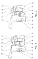
- the switch shown has a switch housing 2, in which a conventional electronic circuit and contact arrangements are situated, with which an electric motor can be driven at different speeds both in the anti-clockwise and clockwise directions.
- a trigger element 3 is seated which can be moved against the pressure of a spring towards the switch housing (to the right in the Figures), on which trigger element a pusher rod 8 is attached which extends towards the switch housing (i.e. to the right in the Figures) and to the inner end of which sliding contacts are attached, in a manner not shown, for co-operation with the circuit elements provided in the interior of the switch housing which contacts move together with pusher rod 8 when the trigger element 3 is displaced.
- a stop element with an inner pin-shaped section 4 and an outer rotary knob 5 is positioned in a through-hole with an interior thread, such that on rotation of the rotary knob 5 the operator can screw this stop element as required into the trigger element 3 and in this way can bring the inner end 6 of the section 4 of the stop element 4, 5 as close as required to the stop-face 7 formed by the switch housing 2.
- a reducing pin 11 is mounted which can be moved to and fro perpendicular to the direction of the possible displacement movement of the trigger element 3, and therefore vertically in the Figures, on which a spring 16, which is attached to a pin 15 on the switch housing 2, acts with a force directed upwards in the Figures.
- the upper end of the reducing pin 11 is chamfered ( Figures 5 and 6), and, in the position for clockwise rotation, this pin projects above an upper face of the switch housing 2 ( Figure 5).
- On this face is the inner section of the adjusting lever 13, which is mounted rotatably on the switch housing 2, so that the operator can pivot it by moving the handle 14 between a position for clockwise rotation and a position for anti-clockwise rotation.
- the adjusting lever 13 effects a switchover in a usual manner, not shown, e.g. by rotation of the armature by means of a di-polar reversing switch, through which the direction of rotation of the electric motor is switched between clockwise and anti-clockwise.
- an oblong anti-clockwise stop 9 is provided, which can, for example, be constructed in one piece with the pusher rod 8, and the lower face of which is adjacent to the upper face of the inner section 4 of the stop element 4,5.
- the inner section 4 of the stop-element 4,5, the anti-clockwise stop 9 and the reducing pin 11 lie somewhat higher, relative to the planes of projection in Figures 1 to 4, than the pusher rod 8, so that these are situated behind the reducing pin 11 and behind the inner section 4 of the stop element 4,5 and can be moved, unimpeded by this, together with the trigger element 3.
- the direction of rotation of the electric motor to be controlled by the switch depends on the position of the adjusting lever 13.
- the speed of the electric motor is determined by the position of the trigger element 3 with regard to the switch housing. In the positions in Figures 1 to 4, the trigger element 3 is situated in the off-position at the greatest distance from the switch housing 2. If the trigger element 3 is moved out of this position towards the switch housing 2 against the spring pressure, i.e. to the right in the Figures, the electric motor is energised, and the further the trigger element 3 is displaced in this direction, the more its speed increases.
- the trigger element 3 can be moved into the switch housing 2 to the point at which the inner end 6 of the stop element 4,5 lies against the stop face 7 of the switch housing 2.
- the stop element 4,5 is screwed further out of the trigger element 3 than in the position shown in Figure 2.
- the stop element 4,5 is in the maximum screwed out position, so that there is a maximum distance of travel for the trigger element 3 and thus a maximum speed can be achieved.
- the stop element 4,5 is screwed as far as possible into the trigger element 3, i.e.
- the inner end 6 of the stop element 4,5 is situated when the trigger element 3 is in the off-position appreciably less distant from the stop-face 7 of the switch housing 2 than in the position in Figure 1.
- the travel of the trigger element 3 is shortened and in this position it is possible to set the minimum speed of the electric motor.
- the lower end of the reducing pin 11 lies above the inner section 4 of the trigger element 4,5 and also above the anti-clockwise rotation stop 9, so that the distances of travel of the trigger element 3 with the pusher rod 8 and stop element 4,5 are not impaired by the reducing pin 11.
- the maximum anti-clockwise rotation speed of the electric motor is clearly lower than the maximum clockwise rotation speed, in order, inter alia, to keep the radio interference, which is more marked in anti-clockwise rotation, below the pre-set limits.
- the trigger element 3 can thus be moved, when in this position, in the same way as when in the corresponding position for clockwise rotation, until the inner end 6 of the stop element 4,5 hits the stop face 7 of the switch housing 2, in order to energise the electric motor corresponding to the minimum speed determined by this position, and the distance of travel available enables the electric motor to be brought up to this minimum speed in a controlled manner.
Landscapes
- Portable Nailing Machines And Staplers (AREA)
- Mechanisms For Operating Contacts (AREA)
- Rotary Switch, Piano Key Switch, And Lever Switch (AREA)
Claims (3)
- Commutateur comprenant un dispositif de circuit pour contrôler la vitesse et pour déterminer le sens de rotation d'un moteur électrique, destiné en particulier à des outils à moteur électrique, ayant un boîtier du commutateur (2) contenant le dispositif de circuit sur lequel est monté un élément de déclenchement (3, 8) qui peut se déplacer vers l'arrière et vers l'avant entre une position d'arrêt éloignée du boîtier du commutateur (2) et une position de marche proche du boîtier du commutateur (2), dans lequel se trouve un élément d'arrêt (4,5) qui peut être déplacé dans le sens du mouvement d'arrière en avant de l'élément de déclenchement (3, 8) entre une position pour la vitesse maximale et une position pour la vitesse minimale, qui limite le mouvement de l'élément de déclenchement (3, 8) dans la position de marche et dont l'extrémité interne faisant face au boîtier du commutateur (2), lorsqu'il est ajusté pour une vitesse maximale dans le réglage pour la rotation en sens horaire du moteur électrique, repose contre une face d'arrêt (7) du boîtier du commutateur (2), ainsi qu'une broche de réduction (11) montée sur le boîtier du commutateur (2), laquelle broche peut être déplacée perpendiculairement au mouvement de l'élément de déclenchement (3, 8) entre une position pour la rotation en sens anti-horaire et une position pour la rotation en sens horaire, laquelle broche est située, lorsqu'elle se trouve dans la position pour la rotation en sens horaire, à l'extérieur du parcours de l'extrémité interne (6) de l'élément d'arrêt (4, 5) et, dans la position pour la rotation en sens anti-horaire, sert d'arrêt pour raccourcir la course de l'élément de déclenchement (3, 8) par rapport à sa distance de déplacement dans la position pour le mouvement horaire, caractérisé en ce que l'élément de déclenchement (3, 8) est pourvu d'un arrêt en sens anti-horaire fixe (9), dont la face d'arrêt interne (10), lorsque l'élément d'arrêt (4, 5) se trouve dans la position pour la vitesse minimale, est plus éloignée de la face d'arrêt (7) du boîtier du commutateur (2) que de la face interne (6) de l'élément d'arrêt (4, 5), et en ce que la broche de réduction (11), dans la position anti-horaire, se situe sur le parcours de l'arrêt en sens anti-horaire (9), et, du moins dans le réglage pour la vitesse maximale, en ce que le mouvement de déclenchement (3, 8) dans le sens de la position de marche est limité par le fait que l'extrémité interne (10) de l'arrêt anti-horaire (9) vient reposer sur la broche de réduction (11).
- Commutateur selon la Revendication 1, dans lequel l'arrêt en sens anti-horaire (9) est disposé au-dessus de la section interne (4) de l'élément d'arrêt (4, 5).
- Commutateur selon la Revendication 1 ou 2, dans lequel l'arrêt en sens anti-horaire (9) et la partie adjacente (8) de l'élément de déclenchement (3, 8) sont construits d'une seule pièce.
Applications Claiming Priority (2)
| Application Number | Priority Date | Filing Date | Title |
|---|---|---|---|
| DE4006466 | 1990-03-01 | ||
| DE4006466A DE4006466A1 (de) | 1990-03-01 | 1990-03-01 | Schalter |
Publications (3)
| Publication Number | Publication Date |
|---|---|
| EP0444907A2 EP0444907A2 (fr) | 1991-09-04 |
| EP0444907A3 EP0444907A3 (en) | 1992-01-08 |
| EP0444907B1 true EP0444907B1 (fr) | 1994-12-14 |
Family
ID=6401220
Family Applications (1)
| Application Number | Title | Priority Date | Filing Date |
|---|---|---|---|
| EP91301607A Expired - Lifetime EP0444907B1 (fr) | 1990-03-01 | 1991-02-27 | Commutateur |
Country Status (2)
| Country | Link |
|---|---|
| EP (1) | EP0444907B1 (fr) |
| DE (2) | DE4006466A1 (fr) |
Families Citing this family (3)
| Publication number | Priority date | Publication date | Assignee | Title |
|---|---|---|---|---|
| DE4225287A1 (de) * | 1992-07-31 | 1994-02-03 | Marquardt Gmbh | Elektrischer Schalter zur Drehzahlregulierung von Motoren |
| DE19636873A1 (de) * | 1996-09-11 | 1998-03-12 | Juergen Schmid | Elektrische Handschleifmaschine |
| DE102006060880A1 (de) * | 2006-12-22 | 2008-06-26 | Metabowerke Gmbh | Elektrohandwerkzeuggerät |
Family Cites Families (7)
| Publication number | Priority date | Publication date | Assignee | Title |
|---|---|---|---|---|
| US3590194A (en) * | 1969-09-19 | 1971-06-29 | Skil Corp | Contact- and circuit-mounting board for trigger-operated switch unit |
| US3742364A (en) * | 1971-10-22 | 1973-06-26 | Lucerne Products Inc | Reversing switch lever |
| US3755640A (en) * | 1972-07-27 | 1973-08-28 | Skie Corp | Reversing switch for a power tool with separate selectively movable contact carriers |
| DE2444739C3 (de) * | 1974-09-19 | 1984-03-15 | Scintilla Ag, Solothurn | Vorrichtung zur Drehzahlsteuerung eines in eine Handwerkzeugmaschine eingebauten Elektromotors |
| US4097705A (en) * | 1977-08-05 | 1978-06-27 | The Singer Company | Quick lock-release mechanism for a trigger switch |
| DE2847140C2 (de) * | 1978-10-30 | 1980-12-04 | Siemens Ag, 1000 Berlin Und 8000 Muenchen | In eine Gehäuseöffnung, insbesondere eines Spielzeugtransformators, von außen eingesteckter Drehknopf |
| DE2920066C2 (de) * | 1979-05-18 | 1984-09-27 | Metabowerke GmbH & Co, 7440 Nürtingen | Elektrohandgerät mit einem für eine Drehrichtung optimierten Universalmotor |
-
1990
- 1990-03-01 DE DE4006466A patent/DE4006466A1/de not_active Withdrawn
-
1991
- 1991-02-27 EP EP91301607A patent/EP0444907B1/fr not_active Expired - Lifetime
- 1991-02-27 DE DE69105776T patent/DE69105776T2/de not_active Expired - Fee Related
Also Published As
| Publication number | Publication date |
|---|---|
| EP0444907A3 (en) | 1992-01-08 |
| DE69105776T2 (de) | 1995-04-27 |
| DE4006466A1 (de) | 1991-09-05 |
| DE69105776D1 (de) | 1995-01-26 |
| EP0444907A2 (fr) | 1991-09-04 |
Similar Documents
| Publication | Publication Date | Title |
|---|---|---|
| US4368444A (en) | Low-voltage protective circuit breaker with locking lever | |
| US5191968A (en) | Shaft lock arrangement for a power tool | |
| EP0064602B2 (fr) | Dispositif automatique de verrouillage pour véhicules | |
| US6550545B1 (en) | Hand-held electrical combination hammer drill | |
| EP0444907B1 (fr) | Commutateur | |
| EP0510985B1 (fr) | Verrouillage mécanique pour deux commutateurs électromagnétiques | |
| US4181838A (en) | Actuating mechanism with an auxiliary switch for an electrically lockable power switch | |
| EP0927426A1 (fr) | Bouton de commande pour appareils electromenagers | |
| US3384722A (en) | Safety switch lock | |
| US5597989A (en) | Switch assembly including cam operated pivoted contact | |
| CN219875705U (zh) | 一种霍尔调速信号开关 | |
| KR20060122807A (ko) | 개폐기용 조작기 | |
| EP0977228A2 (fr) | Interrupteur électromécanique de sécurité à clé avec dispositif de verrouillage électromagnétique | |
| US3845265A (en) | Low profile pressure switch with plunger adjusting means | |
| EP0883148B1 (fr) | Dispositif d'actionnement pour disjoncteur avec interrupteur de mise hors service | |
| JP4061128B2 (ja) | ワイパースイッチ | |
| US3196230A (en) | Snap action pull-push type electric switch | |
| KR100390459B1 (ko) | 배선용 차단기의 순시 가조정 트립장치 | |
| US6727450B2 (en) | Electric switch | |
| KR100323739B1 (ko) | 배선용 차단기의 순시 가조정 트립장치 | |
| WO2006116468A2 (fr) | Dispositif et procede de commutation | |
| EP1017080B1 (fr) | Dipositif auxiliaire | |
| CN222966021U (zh) | 一种调节装置及热过载继电器 | |
| CN218568735U (zh) | 用于接触器的辅助触点设备 | |
| US2935877A (en) | Cam operated holding in switch |
Legal Events
| Date | Code | Title | Description |
|---|---|---|---|
| PUAI | Public reference made under article 153(3) epc to a published international application that has entered the european phase |
Free format text: ORIGINAL CODE: 0009012 |
|
| AK | Designated contracting states |
Kind code of ref document: A2 Designated state(s): CH DE FR GB IT LI |
|
| PUAL | Search report despatched |
Free format text: ORIGINAL CODE: 0009013 |
|
| AK | Designated contracting states |
Kind code of ref document: A3 Designated state(s): CH DE FR GB IT LI |
|
| 17P | Request for examination filed |
Effective date: 19920125 |
|
| 17Q | First examination report despatched |
Effective date: 19940303 |
|
| GRAA | (expected) grant |
Free format text: ORIGINAL CODE: 0009210 |
|
| AK | Designated contracting states |
Kind code of ref document: B1 Designated state(s): CH DE FR GB IT LI |
|
| REF | Corresponds to: |
Ref document number: 69105776 Country of ref document: DE Date of ref document: 19950126 |
|
| ITF | It: translation for a ep patent filed | ||
| ET | Fr: translation filed | ||
| PLBE | No opposition filed within time limit |
Free format text: ORIGINAL CODE: 0009261 |
|
| STAA | Information on the status of an ep patent application or granted ep patent |
Free format text: STATUS: NO OPPOSITION FILED WITHIN TIME LIMIT |
|
| 26N | No opposition filed | ||
| PGFP | Annual fee paid to national office [announced via postgrant information from national office to epo] |
Ref country code: FR Payment date: 19960118 Year of fee payment: 6 |
|
| PGFP | Annual fee paid to national office [announced via postgrant information from national office to epo] |
Ref country code: GB Payment date: 19960119 Year of fee payment: 6 Ref country code: DE Payment date: 19960119 Year of fee payment: 6 |
|
| PGFP | Annual fee paid to national office [announced via postgrant information from national office to epo] |
Ref country code: CH Payment date: 19960202 Year of fee payment: 6 |
|
| PG25 | Lapsed in a contracting state [announced via postgrant information from national office to epo] |
Ref country code: GB Effective date: 19970227 |
|
| PG25 | Lapsed in a contracting state [announced via postgrant information from national office to epo] |
Ref country code: LI Effective date: 19970228 Ref country code: CH Effective date: 19970228 |
|
| GBPC | Gb: european patent ceased through non-payment of renewal fee |
Effective date: 19970227 |
|
| REG | Reference to a national code |
Ref country code: CH Ref legal event code: PL |
|
| PG25 | Lapsed in a contracting state [announced via postgrant information from national office to epo] |
Ref country code: FR Effective date: 19971030 |
|
| PG25 | Lapsed in a contracting state [announced via postgrant information from national office to epo] |
Ref country code: DE Effective date: 19971101 |
|
| REG | Reference to a national code |
Ref country code: FR Ref legal event code: ST |
|
| PG25 | Lapsed in a contracting state [announced via postgrant information from national office to epo] |
Ref country code: IT Free format text: LAPSE BECAUSE OF NON-PAYMENT OF DUE FEES;WARNING: LAPSES OF ITALIAN PATENTS WITH EFFECTIVE DATE BEFORE 2007 MAY HAVE OCCURRED AT ANY TIME BEFORE 2007. THE CORRECT EFFECTIVE DATE MAY BE DIFFERENT FROM THE ONE RECORDED. Effective date: 20050227 |