EP0444909A2 - Hand-held power tool with a rotary driven tool - Google Patents
Hand-held power tool with a rotary driven tool Download PDFInfo
- Publication number
- EP0444909A2 EP0444909A2 EP91301609A EP91301609A EP0444909A2 EP 0444909 A2 EP0444909 A2 EP 0444909A2 EP 91301609 A EP91301609 A EP 91301609A EP 91301609 A EP91301609 A EP 91301609A EP 0444909 A2 EP0444909 A2 EP 0444909A2
- Authority
- EP
- European Patent Office
- Prior art keywords
- safety
- hand
- braking
- trigger
- power tool
- Prior art date
- Legal status (The legal status is an assumption and is not a legal conclusion. Google has not performed a legal analysis and makes no representation as to the accuracy of the status listed.)
- Granted
Links
Images

Classifications
-
- B—PERFORMING OPERATIONS; TRANSPORTING
- B23—MACHINE TOOLS; METAL-WORKING NOT OTHERWISE PROVIDED FOR
- B23Q—DETAILS, COMPONENTS, OR ACCESSORIES FOR MACHINE TOOLS, e.g. ARRANGEMENTS FOR COPYING OR CONTROLLING; MACHINE TOOLS IN GENERAL CHARACTERISED BY THE CONSTRUCTION OF PARTICULAR DETAILS OR COMPONENTS; COMBINATIONS OR ASSOCIATIONS OF METAL-WORKING MACHINES, NOT DIRECTED TO A PARTICULAR RESULT
- B23Q11/00—Accessories fitted to machine tools for keeping tools or parts of the machine in good working condition or for cooling work; Safety devices specially combined with or arranged in, or specially adapted for use in connection with, machine tools
- B23Q11/0078—Safety devices protecting the operator, e.g. against accident or noise
- B23Q11/0092—Safety devices protecting the operator, e.g. against accident or noise actuating braking or stopping means
-
- B—PERFORMING OPERATIONS; TRANSPORTING
- B27—WORKING OR PRESERVING WOOD OR SIMILAR MATERIAL; NAILING OR STAPLING MACHINES IN GENERAL
- B27G—ACCESSORY MACHINES OR APPARATUS FOR WORKING WOOD OR SIMILAR MATERIALS; TOOLS FOR WORKING WOOD OR SIMILAR MATERIALS; SAFETY DEVICES FOR WOOD WORKING MACHINES OR TOOLS
- B27G21/00—Safety guards or devices specially designed for other wood-working machines auxiliary devices facilitating proper operation of said wood-working machines
Definitions
- the invention relates to a hand-held power tool with a rotary driven tool, in particular a planer or a circular saw, in which, on switching off the drive, which can be switched on and off by a switch activator or trigger, a brake element, which is ineffective when the drive is switched on, is brought into braking engagement with a brake part which is rotatingly driven by the drive.
- a brake band is provided for rapidly braking the rotating tool which brake band, when the power supply is interrupted, is pulled by spring action into engagement with a pulley surrounded by the brake band and thus causes a braking action.
- the brake band is coupled with an electromagnet such that the excitation of the latter releases the brake band from its engagement with the pulley by means of pivoting flaps.
- the object of the invention is to improve a hand-held power tool with a rotary driven tool in such a way that in a simple and compact construction rapid braking of the rotating tool is effected when the drive is switched off.
- a hand-held power tool of the type mentioned in the introduction is constructed according to the invention so that the switch activator or trigger, co-operates with a safety element which can be shifted between a safety position in which the trigger cannot be moved to switch on the drive, and a release position, in which the trigger can be moved into position to switch on the drive, in which spring means urges the safety element in the direction of the safety position, and the safety element is held in the release position when the trigger is in the switch-on position, and such that the safety element is coupled mechanically with the brake element, so that the brake element is disengaged from the braking position when the safety element is in the release position and is in braking engagement when the safety element is in the safety position.
- a safety element which is usual per se and which co-operates with the trigger.
- Such safety element ensures that it is only possible to switch on the hand-held power tool if the safety element has been moved into the release position beforehand by the operator. This prevents the drive from being activated by accidental displacement of the trigger in such power tool.
- the safety element is coupled mechanically with the brake element, so that when the safety element is moved into the release position, the brake element is moved out of the braking position, i.e. the braking engagement is cancelled, before the trigger can be moved into the position to switch on the drive. Since the safety element is held in the release position when the trigger is in the switch-on position, i.e. when the drive is activated, the brake element is also held out of braking engagement while the drive is switched on.
- the braking engagement is effected and cancelled depending on the movement of the safety element, which is mechanically coupled with the brake element, so that apart from the relatively simple coupling no additional components or measures are necessary.
- the brake element is preferably spring urged into braking engagement, so that when the safety element moves into the safety position it is pushed into braking engagement without the operator, who has displaced the safety element, having to apply any additional braking force.
- the brake element when the safety element is in the safety position the brake element is in frictional engagement with a braking surface formed on the brake part, and therefore the brake element operates like a conventional friction brake, which means on the one hand that the brake element and braking surface are of simple construction and on the other that, due to the frictional forces which build up when the braking engagement is produced, a relatively uniform, shock-free braking process is achieved.
- the braking surface can be formed on an exterior surface lying concentric to the axis of rotation, and can consist, for example, of an annular groove the side walls of which converge to the base of the groove so that the brake element can enter this annular groove and can engage with the side walls of the annular groove.
- the brake element comprises a rigid body which is pivotably mounted towards one end on an axle, and is connected towards the other end with the safety element.
- the rotating braking surface moves lengthwise of the brake element.
- the mechanical coupling between safety element and brake element consists of a rod linkage.
- Figure 1 shows a perspective representation of a hand-held planer.
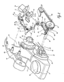
- Figure 2 shows an exploded detailed representation of parts of the casing of the hand-held planer of Figure 1 and also an arrangement housed in a casing of the planer for bringing the planer to rest.
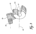
- Figure 3 shows a perspective partial representation of a brake element and a pulley forming a braking surface.
- the hand-held planer 1 shown in Figure 1 has a casing composed of two halves 2, 3, with a detachable cover 4 screwed on to a projecting edge 39 on the outside of casing half 3.
- the casing halves 2, 3 of the casing form a forward-projecting additional handle 8 and also a grip opening 9, into which a switch activator or trigger 15 projects in the usual manner and is used to activate an on/off switch of the planer.
- the trigger 15, as will be described later, can only be moved into the on-position if a safety switch member 20 projecting from the top of the casing has been shifted beforehand.
- a sawdust vent is provided in casing half 3 in the form of a laterally projecting tubular connector 10.
- casing half 3 On the under-side of the casing halves 2, 3, there is a stationary shoe 6 and a front shoe section 5, which can be moved up and down in a known manner to adjust the depth of cut, the height of which can be altered by means of a rotary knob 7.
- a cable 11 for connecting the hand-held planer 1 to a power supply is passed into the casing at its rear end.
- planer 1 is essentially conventional in its interior construction, and therefore only the parts which appear necessary for the explanation of the invention are shown in Figure 2.
- a tubular section 42 of the casing half 3 Adjacent the bearing pin 37, a tubular section 42 of the casing half 3 comprises a bearing 43 for a cutter shaft 50; the cutter shaft 50 extends into the casing 2, 3, to receive a cutter head while a pulley 51 is fixed on a part of the cutter shaft 50 which projects through the section 42; a continuous drive belt 54 passes round a circumferential surface 52 of the pulley 51 and a pulley 46′, which is fixed to an armature shaft of an electric motor, (not shown) which extends coaxially to an axis 46.
- the pulley 46′ is positioned adjacent to an annular casing projection 45, formed on the outside of the casing half 3.
- the trigger 15 (which is also shown in Figure 2) extends partly into the casing halves 2, 3 and partly into the grip opening 9.
- a housing 16 containing a switch is mounted inside the casing, next to the trigger 15, so that when the trigger 15 is displaced in the direction of the arrow A ( Figure 2), and therefore into the casing 2, 3, an actuator part 17 of the switch is pushed into the switch housing 16 and thus the switch contacts are closed.
- an oblong, essentially flat, safety element 21 is mounted in longitudinal tracks, not shown, formed in the casing 2,3, so that it can be reciprocated in the direction of its longitudinal extension.
- the safety element 21 comprises two cut-outs 21′ in one side, of sizes and spacing of which matched the sizes and spacing of projections 15′ formed on the trigger 15.
- the trigger 15 can therefore only be displaced inwards into the casing in the direction of the arrow A, and consequently into the switch-on position, if the safety element 21 is pushed into a position in which its cut-outs 21′ are aligned with the projections 15′ so that the projections 15′ of the trigger 15 displaced in the direction of the arrow A mesh into the cut-outs 21′. Sufficient movement of the trigger 15 in the direction of the arrow A can take place for the switch to be brought into its on-position. Moreover, the meshing of the projections 15′ with the cut-outs 21′ ensures that the safety element 21, which can move to and fro in the direction of its longitudinal extension and therefore perpendicular to the direction of movement A, cannot be moved out of position.
- an operating lever 23 Pivotally attached by a pin 22 on an outer end of the safety element 21 is an operating lever 23 which is provided on its end adjacent to the pin 22 with the safety switch member 20, which forms a grip surface for the operation of the safety element 21.
- the lever 23 in its centre region forms a bush-shaped bearing section 24 which, when the tool is assembled, sits on the bearing pin 44.
- the lever 23 On its end opposite the pin 22, the lever 23 comprises a bearing shell 25 with which a cross-pin-shaped end of an L shaped lever 26 is coupled so that it can pivot.
- the lever 26 has a bush-shaped bearing section 27, which, when the tool is assembled, sits on the bearing pin 47, and is able to pivot.
- a spring 28 On the bush-shaped bearing section 27 of the lever 26 there is positioned a spring 28 which engage a top side of the lever 23 and thus exerts a return force, acting in the direction of the downward pointing part of arrow C, on that end of the lever 23 which comprises the bearing shell 25.
- the end of the L shaped lever 26 opposite the lever 23 is pivotally connected by a pin 29 to a link-lever 30 which is bent at its ends and, when the tool is assembled, extends outwards with its middle section parallel to the longitudinal axes of the ;bearing pins 44 and 47, so that its outer end, on which a pivot connection 31 is provided, extends into the region which is covered by the cover 4 as shown in Figure 1.
- the link-lever 30 is connected at the pivot connection 31 with an articulated lever 32 which has an extended hole 233 in the region of the pivot connection 31.
- the other end of the lever 32 is connected so that it pivots about an axis 35 on one end of a brake element 34.
- the articulated lever 32 lies in a plane which is normal to the middle axes of the bush-shaped bearing sections 24 and 27.
- the brake element 34 is plate shaped and consists of the usual brake block material for motor vehicle brakes, for example a thermosetting resin, and has its end opposite the pivot axis 35 pivotally mounted on the bearing pin 37 and held in position by a split washer 38.
- a helical spring 36 which comprises a rear, up-standing end portion which bears, in a manner not shown, on the protruding edge 39 of the casing half 3.
- the other end of the spring 36, near the pivot axis 35, lies on the top of the brake element 34, so that (viewing Figure 2) the brake element 34 is under a force acting in the direction of the downward pointing part of the arrow E, i.e. a force which acts in the direction of rotation of the brake element 34 clockwise around the bearing pin 37.
- the cutter shaft 50 which is carried so that it rotates in the bearing 43.
- the pulley 51 which consists, for example, of free-cutting steel, is non-rotatably attached, so that when driven it is moved in the direction of the arrow F.
- annular slot 53 is formed around its circumference, the side walls of which converge to the base of the slot ( Figure 3).
- a lower section of the brake element 34 extends into the slot 53, and is curved to match the annular slot 53. In the condition shown in Figure 2, where the safety element 21 is in the safety position, the lower section of the brake element 34 is pushed by the force of the spring 36 into braking frictional engagement with the side walls of the annular slot 53, thus preventing rotation of the cutter shaft 50.
- a cutter head not shown, attached to the cutter shaft 50, is rotated.
- the operator pushes the safety switch member 20, so that the lever 23 is pivoted on the bearing pin 44 in the direction of the arrow B against the force of the spring 28.
- the safety element 21 which is pivotably connected via the pin 22 with the lever 23, is shifted in the direction of its longitudinal extension, so that the cut-outs 21′ move into alignment with the projections 15′ of the trigger 15 and the latter can be shifted in the direction of the arrow A to push in the actuator part 17 and therefore to switch on the on/off switch of the hand-held planer 1.
- the trigger 15 is pressed into the casing in the direction of the arrow A, then, as already mentioned above the on/off switch is switched on and thus the drive motor of the hand-held planer 1 is activated, which drives the pulley 51 and with it the cutter head seated on the cutter shaft 50 by means of the continuous drive belt 54.
- the trigger 15 is in this pressed-in position the projections 15′ of the trigger 15 are situated in the cut-outs 21′ of the safety element 21, and the latter is therefore held in the position set by pivoting the safety switch member 20 for as long as the operator holes the on/off switch in the switch-on condition with the trigger.
Landscapes
- Life Sciences & Earth Sciences (AREA)
- Engineering & Computer Science (AREA)
- Mechanical Engineering (AREA)
- Wood Science & Technology (AREA)
- Forests & Forestry (AREA)
- Milling, Drilling, And Turning Of Wood (AREA)
- Harvester Elements (AREA)
- Sawing (AREA)
Abstract
Description
- The invention relates to a hand-held power tool with a rotary driven tool, in particular a planer or a circular saw, in which, on switching off the drive, which can be switched on and off by a switch activator or trigger, a brake element, which is ineffective when the drive is switched on, is brought into braking engagement with a brake part which is rotatingly driven by the drive.
- In a known hand-held power tool of this type (EP-A-0 042 918), inter alia, a brake band is provided for rapidly braking the rotating tool which brake band, when the power supply is interrupted, is pulled by spring action into engagement with a pulley surrounded by the brake band and thus causes a braking action. The brake band is coupled with an electromagnet such that the excitation of the latter releases the brake band from its engagement with the pulley by means of pivoting flaps.
- This known construction, therefore, in addition to the drive motor for the electric power tool and the circuit arrangement co-operating therewith, requires an electromagnet by means of which the brake band is released from braking engagement with a pulley. Not only are the production costs increased thereby, but in addition, the electromagnet also takes up a relatively large amount of space so that the total dimensions of the hand-held power tool are relatively large.
- The object of the invention is to improve a hand-held power tool with a rotary driven tool in such a way that in a simple and compact construction rapid braking of the rotating tool is effected when the drive is switched off.
- To achieve this object a hand-held power tool of the type mentioned in the introduction is constructed according to the invention so that the switch activator or trigger, co-operates with a safety element which can be shifted between a safety position in which the trigger cannot be moved to switch on the drive, and a release position, in which the trigger can be moved into position to switch on the drive, in which spring means urges the safety element in the direction of the safety position, and the safety element is held in the release position when the trigger is in the switch-on position, and such that the safety element is coupled mechanically with the brake element, so that the brake element is disengaged from the braking position when the safety element is in the release position and is in braking engagement when the safety element is in the safety position.
- In the hand-held power tool according to the invention, therefore there is a safety element, which is usual per se and which co-operates with the trigger. Such safety element ensures that it is only possible to switch on the hand-held power tool if the safety element has been moved into the release position beforehand by the operator. This prevents the drive from being activated by accidental displacement of the trigger in such power tool.
- In the hand-held power tool according to the invention, the safety element is coupled mechanically with the brake element, so that when the safety element is moved into the release position, the brake element is moved out of the braking position, i.e. the braking engagement is cancelled, before the trigger can be moved into the position to switch on the drive. Since the safety element is held in the release position when the trigger is in the switch-on position, i.e. when the drive is activated, the brake element is also held out of braking engagement while the drive is switched on.
- When the trigger returns to the switch-off position, the safety element is released and due to the spring means acting on it returns to the safety position. Due to the mechanical coupling this movement into the safety position causes the brake element to move into braking engagement and therefore brings to a halt the tool which otherwise would still be rotating.
- In the hand-held power tool according to the invention, therefore, the braking engagement is effected and cancelled depending on the movement of the safety element, which is mechanically coupled with the brake element, so that apart from the relatively simple coupling no additional components or measures are necessary.
- The brake element is preferably spring urged into braking engagement, so that when the safety element moves into the safety position it is pushed into braking engagement without the operator, who has displaced the safety element, having to apply any additional braking force.
- In a particularly preferred embodiment of the invention, when the safety element is in the safety position the brake element is in frictional engagement with a braking surface formed on the brake part, and therefore the brake element operates like a conventional friction brake, which means on the one hand that the brake element and braking surface are of simple construction and on the other that, due to the frictional forces which build up when the braking engagement is produced, a relatively uniform, shock-free braking process is achieved.
- The braking surface can be formed on an exterior surface lying concentric to the axis of rotation, and can consist, for example, of an annular groove the side walls of which converge to the base of the groove so that the brake element can enter this annular groove and can engage with the side walls of the annular groove.
- The brake element comprises a rigid body which is pivotably mounted towards one end on an axle, and is connected towards the other end with the safety element. The rotating braking surface moves lengthwise of the brake element.
- In a construction of this type, if the edge of the section of the brake element facing the braking surface, which section which lies between the end regions and comes in contact with the braking surface, is curved corresponding to the braking surface, not only is there contact over a large surface area, but the engagement between the braking surface and the brake element can increase somewhat during the braking process.
- In a particularly simple construction the mechanical coupling between safety element and brake element consists of a rod linkage.
- The invention is explained in more detail in the following description with reference to the accompanying drawings of a preferred embodiment in the form of an electrically powered hand-held planer.
- Figure 1 shows a perspective representation of a hand-held planer.
- Figure 2 shows an exploded detailed representation of parts of the casing of the hand-held planer of Figure 1 and also an arrangement housed in a casing of the planer for bringing the planer to rest.
- Figure 3 shows a perspective partial representation of a brake element and a pulley forming a braking surface.
- The hand-held planer 1 shown in Figure 1 has a casing composed of two
halves detachable cover 4 screwed on to a projectingedge 39 on the outside ofcasing half 3. Thecasing halves additional handle 8 and also a grip opening 9, into which a switch activator or trigger 15 projects in the usual manner and is used to activate an on/off switch of the planer. Thetrigger 15, as will be described later, can only be moved into the on-position if asafety switch member 20 projecting from the top of the casing has been shifted beforehand. - Between the
safety switch member 20 and the cover 4 a sawdust vent is provided incasing half 3 in the form of a laterally projectingtubular connector 10. On the under-side of thecasing halves rotary knob 7. A cable 11 for connecting the hand-held planer 1 to a power supply is passed into the casing at its rear end. - The planer 1 is essentially conventional in its interior construction, and therefore only the parts which appear necessary for the explanation of the invention are shown in Figure 2.
- With reference to the left-hand side of Figure 2, in which the
casing halves cover 4 of Figure 1 and also with a top part of thecasing half 3 cut away, a receivingopening 41 for adjustment mechanism connected to therotary knob 7 for the front shoe section 5 and also a recess 40 for receiving thesafety switch member 20 can be seen.Bearing pins 44, 47 are formed in thecasing half 2, and abearing pin 37 is provided in the region of theprotruding edge 39 of thecasing half 3. - Adjacent the
bearing pin 37, a tubular section 42 of thecasing half 3 comprises a bearing 43 for acutter shaft 50; thecutter shaft 50 extends into thecasing pulley 51 is fixed on a part of thecutter shaft 50 which projects through the section 42; a continuous drive belt 54 passes round acircumferential surface 52 of thepulley 51 and apulley 46′, which is fixed to an armature shaft of an electric motor, (not shown) which extends coaxially to anaxis 46. Thepulley 46′ is positioned adjacent to anannular casing projection 45, formed on the outside of thecasing half 3. - As can be seen from Figure 1, the trigger 15 (which is also shown in Figure 2) extends partly into the
casing halves housing 16 containing a switch is mounted inside the casing, next to thetrigger 15, so that when thetrigger 15 is displaced in the direction of the arrow A (Figure 2), and therefore into thecasing actuator part 17 of the switch is pushed into theswitch housing 16 and thus the switch contacts are closed. - Between the
trigger 15 and theactuator part 17 of the switch, an oblong, essentially flat,safety element 21 is mounted in longitudinal tracks, not shown, formed in thecasing safety element 21 comprises two cut-outs 21′ in one side, of sizes and spacing of which matched the sizes and spacing ofprojections 15′ formed on thetrigger 15. Thetrigger 15 can therefore only be displaced inwards into the casing in the direction of the arrow A, and consequently into the switch-on position, if thesafety element 21 is pushed into a position in which its cut-outs 21′ are aligned with theprojections 15′ so that theprojections 15′ of thetrigger 15 displaced in the direction of the arrow A mesh into the cut-outs 21′. Sufficient movement of thetrigger 15 in the direction of the arrow A can take place for the switch to be brought into its on-position. Moreover, the meshing of theprojections 15′ with the cut-outs 21′ ensures that thesafety element 21, which can move to and fro in the direction of its longitudinal extension and therefore perpendicular to the direction of movement A, cannot be moved out of position. - Pivotally attached by a
pin 22 on an outer end of thesafety element 21 is anoperating lever 23 which is provided on its end adjacent to thepin 22 with thesafety switch member 20, which forms a grip surface for the operation of thesafety element 21. Thelever 23 in its centre region forms a bush-shaped bearing section 24 which, when the tool is assembled, sits on the bearing pin 44. On its end opposite thepin 22, thelever 23 comprises abearing shell 25 with which a cross-pin-shaped end of an Lshaped lever 26 is coupled so that it can pivot. - The
lever 26 has a bush-shaped bearing section 27, which, when the tool is assembled, sits on thebearing pin 47, and is able to pivot. On the bush-shapedbearing section 27 of thelever 26 there is positioned aspring 28 which engage a top side of thelever 23 and thus exerts a return force, acting in the direction of the downward pointing part of arrow C, on that end of thelever 23 which comprises thebearing shell 25. - The end of the L shaped
lever 26 opposite thelever 23 is pivotally connected by apin 29 to a link-lever 30 which is bent at its ends and, when the tool is assembled, extends outwards with its middle section parallel to the longitudinal axes of the ;bearingpins 44 and 47, so that its outer end, on which apivot connection 31 is provided, extends into the region which is covered by thecover 4 as shown in Figure 1. - The link-
lever 30 is connected at thepivot connection 31 with an articulatedlever 32 which has an extended hole 233 in the region of thepivot connection 31. The other end of thelever 32 is connected so that it pivots about anaxis 35 on one end of abrake element 34. The articulatedlever 32 lies in a plane which is normal to the middle axes of the bush-shapedbearing sections - The
brake element 34, is plate shaped and consists of the usual brake block material for motor vehicle brakes, for example a thermosetting resin, and has its end opposite thepivot axis 35 pivotally mounted on thebearing pin 37 and held in position by asplit washer 38. Around thebearing pin 37 is mounted ahelical spring 36 which comprises a rear, up-standing end portion which bears, in a manner not shown, on theprotruding edge 39 of thecasing half 3. The other end of thespring 36, near thepivot axis 35, lies on the top of thebrake element 34, so that (viewing Figure 2) thebrake element 34 is under a force acting in the direction of the downward pointing part of the arrow E, i.e. a force which acts in the direction of rotation of thebrake element 34 clockwise around thebearing pin 37. - As already mentioned above, next to the
bearing pin 37 is thecutter shaft 50, which is carried so that it rotates in the bearing 43. On an outer end theshaft 50, thepulley 51 which consists, for example, of free-cutting steel, is non-rotatably attached, so that when driven it is moved in the direction of the arrow F. Towards the inner face of thepulley 51 anannular slot 53 is formed around its circumference, the side walls of which converge to the base of the slot (Figure 3). A lower section of thebrake element 34 extends into theslot 53, and is curved to match theannular slot 53. In the condition shown in Figure 2, where thesafety element 21 is in the safety position, the lower section of thebrake element 34 is pushed by the force of thespring 36 into braking frictional engagement with the side walls of theannular slot 53, thus preventing rotation of thecutter shaft 50. - In use of the planer 1, a cutter head, not shown, attached to the
cutter shaft 50, is rotated. To achieve this the operator pushes thesafety switch member 20, so that thelever 23 is pivoted on the bearing pin 44 in the direction of the arrow B against the force of thespring 28. Through this pivot movement thesafety element 21, which is pivotably connected via thepin 22 with thelever 23, is shifted in the direction of its longitudinal extension, so that the cut-outs 21′ move into alignment with theprojections 15′ of thetrigger 15 and the latter can be shifted in the direction of the arrow A to push in theactuator part 17 and therefore to switch on the on/off switch of the hand-held planer 1. - This pivotal movement of the
lever 23 in the direction of the arrow B results in swinging the end of the Lshaped lever 26 which is coupled with thelever 23 in the direction of the upward pointing part of arrow C, thus rotating the bush-form bearingsection 27, seated on thebearing pin 47, in the direction of the downward pointing part of arrow D. This movement causes link-lever 30 to move upwards corresponding to the arrow G. As a result, thepivot connection 31 in theextended hole 33 of the link-lever 32 is displaced in the direction of the upward pointing part of the arrow E so that it engages with the upper end of thehole 33, and through the link-lever 32 thebrake element 34 is pivoted anti-clockwise around thebearing pin 37. In this way thebrake element 34 is disengaged from the side walls of theannular slot 53 of the pulley 51 (Figure 3). - If, when the
brake element 34 is in this position, brought abut by depression of thesafety switch member 20, thetrigger 15 is pressed into the casing in the direction of the arrow A, then, as already mentioned above the on/off switch is switched on and thus the drive motor of the hand-held planer 1 is activated, which drives thepulley 51 and with it the cutter head seated on thecutter shaft 50 by means of the continuous drive belt 54. When thetrigger 15 is in this pressed-in position theprojections 15′ of thetrigger 15 are situated in the cut-outs 21′ of thesafety element 21, and the latter is therefore held in the position set by pivoting thesafety switch member 20 for as long as the operator holes the on/off switch in the switch-on condition with the trigger. - If the operator interrupts the power supply for the drive motor by releasing the
trigger 15 and by the resulting displacement of thetrigger 15 outwards by the spring force exerted from the switch side, then in the switch-off state of the switch theprojections 15′ of thetrigger 15 come out of mesh with thesafety element 21. As a result, due to the actions of thesprings lever 23 is pivoted back in the direction of the arrow B into its starting position, and therectangular lever 26 is pivoted in the direction of the downward pointing part of arrow D, so that the link-lever 30 moves in the direction of the downward pointing part of the arrow E and thebrake element 34 is pressed by thespring 36 into engagement with the side walls of theannular slot 53, which results in the immediate braking of thecutter shaft 50 and consequently in the cutter head being brought to a halt. - Using the described arrangement, therefore, there is a mechanical braking of the cutter shaft on the release of the trigger and on the associated switching-off of the drive motor of the hand-held planer without the operator having to carry out any additional operations.
Claims (10)
- Hand-held power tool with a rotary driven tool, in particular a planer or circular saw, in which on switching off the drive, which can be switched on and off by means of a trigger (15), a brake element (34) which is ineffective when the drive is switched on, and can be brought into braking engagement with a braking part (51) which is rotatingly driven by the drive, characterized in that the trigger, (15) co-operates with a safety element (21) which can be shifted between a safety position in which the trigger (15) cannot be moved to switch on the drive, and a release position in which the trigger (15) can be moved into position to switch on the drive, in which spring means urges the safety element (21) in the direction of the safety position and the safety element (21) is held in the release position when the trigger (15) is in the switch-on position, and such that the safety element (21) is coupled mechanically with the brake element (34) so that the brake element is disengaged from the braking position when the safety element (21) is in the release position and is in braking engagement when the safety element (21) is in the safety position.
- Hand-held power tool according to claim 1, characterized in that the direction of movement of the safety element (21) between the safety position and the release position runs perpendicular to the direction (A) of the movement of the trigger (15).
- Hand-held power tool according to claim 1 or 2, characterized in that the brake element (35) is spring hinged towards braking engagement.
- Hand-held power tool according to one of claims 1 to 3, characterized in that when the safety element (21) is in its safety position the brake element (34) is in frictional engagement with a braking surface (53) formed on the braking part (51).
- Hand-held power tool according to claim 4, characterized in that the braking surface (53) is formed on an exterior surface lying concentric to the axis of rotation (50) of the braking part (51).
- Hand-held power tool according to claim 5, characterized in that the braking surface (53) is formed by an annular slot side walls of which converge to the base of the slot.
- Hand-held power tool according to claim 5 or 6, characterized in that the braking part consists of a cylindrical section (51) non-rotatably mounted of the shaft (50) bearing the tool.
- Hand-held power tool according to claim 7, characterized in that the cylindrical section (51) is a pulley.
- Hand-held power tool according to one of claims 4 to 8, characterized in that the brake element (34) comprises of a rigid body which is pivotably mounted toward one end on an axle (37)and is connected towards the other end with the safety element (21), and is arranged so that the rotating braking surface (53) moves lengthwise of the brake element (34).
- Hand-held power tool according to claim 9, characterized in that the brake element (34) comprises a section facing the braking surface (53) which section lies between the end portions of the element (34) and comes into engagement with the braking surface (53) and is curved to match the braking surface (53).
Applications Claiming Priority (2)
| Application Number | Priority Date | Filing Date | Title |
|---|---|---|---|
| DE4007030A DE4007030A1 (en) | 1990-03-02 | 1990-03-02 | POWER-DRIVEN MACHINE TOOL WITH A ROTATING DRIVE |
| DE4007030 | 1990-03-02 |
Publications (3)
| Publication Number | Publication Date |
|---|---|
| EP0444909A2 true EP0444909A2 (en) | 1991-09-04 |
| EP0444909A3 EP0444909A3 (en) | 1991-11-21 |
| EP0444909B1 EP0444909B1 (en) | 1994-03-30 |
Family
ID=6401534
Family Applications (1)
| Application Number | Title | Priority Date | Filing Date |
|---|---|---|---|
| EP91301609A Expired - Lifetime EP0444909B1 (en) | 1990-03-02 | 1991-02-27 | Hand-held power tool with a rotary driven tool |
Country Status (3)
| Country | Link |
|---|---|
| US (1) | US5094000A (en) |
| EP (1) | EP0444909B1 (en) |
| DE (2) | DE4007030A1 (en) |
Cited By (1)
| Publication number | Priority date | Publication date | Assignee | Title |
|---|---|---|---|---|
| WO2013164118A1 (en) * | 2012-05-04 | 2013-11-07 | Robert Bosch Gmbh | Machine tool braking device |
Families Citing this family (82)
| Publication number | Priority date | Publication date | Assignee | Title |
|---|---|---|---|---|
| DE4120875C2 (en) * | 1991-06-21 | 2000-06-08 | Stihl Maschf Andreas | Motor chain saw with brake device integrated in the sprocket cover |
| DE4134768A1 (en) * | 1991-10-22 | 1993-04-29 | Bosch Gmbh Robert | HAND PLANER |
| US5237752A (en) * | 1992-02-20 | 1993-08-24 | Daryl Maseck | Movable control-handle for chainsaw |
| EP0558253A1 (en) * | 1992-02-28 | 1993-09-01 | Black & Decker Inc. | Improvements in dust collection |
| US5463816A (en) * | 1994-05-10 | 1995-11-07 | Ryobi North America | Portable planer with adjustable chip deflector |
| US5778747A (en) * | 1996-11-21 | 1998-07-14 | Rexon Industrial Corp., Ltd. | Power saw having an ergonomically-designed handle and safety switch |
| US6091035A (en) | 1998-08-14 | 2000-07-18 | Black & Decker, Inc. | Lockout mechanism for power tool |
| US6057518A (en) * | 1998-08-14 | 2000-05-02 | Black & Decker, Inc. | Lockout mechanism for power tool |
| US8061245B2 (en) | 2000-09-29 | 2011-11-22 | Sd3, Llc | Safety methods for use in power equipment |
| US7827890B2 (en) | 2004-01-29 | 2010-11-09 | Sd3, Llc | Table saws with safety systems and systems to mount and index attachments |
| US7024975B2 (en) | 2000-08-14 | 2006-04-11 | Sd3, Llc | Brake mechanism for power equipment |
| US7098800B2 (en) | 2003-03-05 | 2006-08-29 | Sd3, Llc | Retraction system and motor position for use with safety systems for power equipment |
| US20050041359A1 (en) | 2003-08-20 | 2005-02-24 | Gass Stephen F. | Motion detecting system for use in a safety system for power equipment |
| US7377199B2 (en) | 2000-09-29 | 2008-05-27 | Sd3, Llc | Contact detection system for power equipment |
| US7836804B2 (en) | 2003-08-20 | 2010-11-23 | Sd3, Llc | Woodworking machines with overmolded arbors |
| US7712403B2 (en) | 2001-07-03 | 2010-05-11 | Sd3, Llc | Actuators for use in fast-acting safety systems |
| US7536238B2 (en) | 2003-12-31 | 2009-05-19 | Sd3, Llc | Detection systems for power equipment |
| US6857345B2 (en) | 2000-08-14 | 2005-02-22 | Sd3, Llc | Brake positioning system |
| US7509899B2 (en) | 2000-08-14 | 2009-03-31 | Sd3, Llc | Retraction system for use in power equipment |
| US9724840B2 (en) * | 1999-10-01 | 2017-08-08 | Sd3, Llc | Safety systems for power equipment |
| US7210383B2 (en) | 2000-08-14 | 2007-05-01 | Sd3, Llc | Detection system for power equipment |
| US7171879B2 (en) | 2001-07-02 | 2007-02-06 | Sd3, Llc | Discrete proximity detection system |
| US20030056853A1 (en) | 2001-09-21 | 2003-03-27 | Gass Stephen F. | Router with improved safety system |
| US7137326B2 (en) | 2000-08-14 | 2006-11-21 | Sd3, Llc | Translation stop for use in power equipment |
| US7610836B2 (en) | 2000-08-14 | 2009-11-03 | Sd3, Llc | Replaceable brake mechanism for power equipment |
| US9927796B2 (en) | 2001-05-17 | 2018-03-27 | Sawstop Holding Llc | Band saw with improved safety system |
| US7707920B2 (en) | 2003-12-31 | 2010-05-04 | Sd3, Llc | Table saws with safety systems |
| US8459157B2 (en) | 2003-12-31 | 2013-06-11 | Sd3, Llc | Brake cartridges and mounting systems for brake cartridges |
| US7055417B1 (en) | 1999-10-01 | 2006-06-06 | Sd3, Llc | Safety system for power equipment |
| US7225712B2 (en) | 2000-08-14 | 2007-06-05 | Sd3, Llc | Motion detecting system for use in a safety system for power equipment |
| US7290472B2 (en) | 2002-01-14 | 2007-11-06 | Sd3, Llc | Miter saw with improved safety system |
| US7077039B2 (en) | 2001-11-13 | 2006-07-18 | Sd3, Llc | Detection system for power equipment |
| US7231856B2 (en) | 2001-06-13 | 2007-06-19 | Sd3, Llc | Apparatus and method for detecting dangerous conditions in power equipment |
| US20020017179A1 (en) | 2000-08-14 | 2002-02-14 | Gass Stephen F. | Miter saw with improved safety system |
| US7472634B2 (en) | 2003-08-20 | 2009-01-06 | Sd3, Llc | Woodworking machines with overmolded arbors |
| US7197969B2 (en) | 2001-09-24 | 2007-04-03 | Sd3, Llc | Logic control with test mode for fast-acting safety system |
| US7000514B2 (en) | 2001-07-27 | 2006-02-21 | Sd3, Llc | Safety systems for band saws |
| US7353737B2 (en) | 2001-08-13 | 2008-04-08 | Sd3, Llc | Miter saw with improved safety system |
| US7308843B2 (en) | 2000-08-14 | 2007-12-18 | Sd3, Llc | Spring-biased brake mechanism for power equipment |
| US7100483B2 (en) | 2000-08-14 | 2006-09-05 | Sd3, Llc | Firing subsystem for use in a fast-acting safety system |
| US7284467B2 (en) | 2000-08-14 | 2007-10-23 | Sd3, Llc | Apparatus and method for detecting dangerous conditions in power equipment |
| US8065943B2 (en) | 2000-09-18 | 2011-11-29 | Sd3, Llc | Translation stop for use in power equipment |
| US7350445B2 (en) | 2003-08-20 | 2008-04-01 | Sd3, Llc | Brake cartridge for power equipment |
| US7350444B2 (en) * | 2000-08-14 | 2008-04-01 | Sd3, Llc | Table saw with improved safety system |
| US7600455B2 (en) | 2000-08-14 | 2009-10-13 | Sd3, Llc | Logic control for fast-acting safety system |
| US7481140B2 (en) | 2005-04-15 | 2009-01-27 | Sd3, Llc | Detection systems for power equipment |
| US6994004B2 (en) | 2000-09-29 | 2006-02-07 | Sd3, Llc | Table saw with improved safety system |
| US6633046B1 (en) * | 2000-04-19 | 2003-10-14 | Applied Materials, Inc. | Method and apparatus for detecting that two moveable members are correctly positioned relatively to one another |
| US7856724B2 (en) * | 2000-08-17 | 2010-12-28 | Hilti Aktiengesellschaft | Electrical power tool with a rotatable working tool |
| DE10040332B4 (en) * | 2000-08-17 | 2009-03-05 | Hilti Aktiengesellschaft | Power tool with rotating tool and a braking device |
| US7168502B2 (en) * | 2000-08-17 | 2007-01-30 | Hilti Aktiengesellschaft | Electric power tool with locking mechanism |
| DE10048675A1 (en) * | 2000-09-30 | 2002-04-18 | Festool Gmbh | Hand tool |
| DE20104536U1 (en) * | 2001-03-16 | 2001-05-23 | Andreas Stihl AG & Co., 71336 Waiblingen | Hand-held, portable work tool with thumb supports |
| USD495574S1 (en) | 2001-08-24 | 2004-09-07 | Robert Bosch Gmbh | Planer |
| DE20203683U1 (en) * | 2002-03-08 | 2003-07-24 | Robert Bosch Gmbh, 70469 Stuttgart | Portable planer |
| USD475594S1 (en) | 2002-05-13 | 2003-06-10 | Positec Power Tools (Suzhou) Co., Ltd. | Planer |
| USD492563S1 (en) | 2003-05-27 | 2004-07-06 | Black & Decker Inc. | Belt sander |
| USD509721S1 (en) * | 2003-09-17 | 2005-09-20 | Gmca Pty Limited | Planer |
| USD497298S1 (en) | 2003-12-16 | 2004-10-19 | One World Technologies, Limited | Belt sander |
| AU156895S (en) * | 2004-02-18 | 2004-11-15 | Bosch Gmbh Robert | Planer |
| USD501775S1 (en) * | 2004-03-09 | 2005-02-15 | One World Technologies, Limited | Hand planer |
| US20050284543A1 (en) * | 2004-06-23 | 2005-12-29 | One World Technologies Limited | Pre-directing insert for a bi-directional exhausting handheld planer |
| USD508833S1 (en) | 2004-09-24 | 2005-08-30 | One World Technologies Limited | Planer |
| AU307350S (en) * | 2005-10-26 | 2006-06-08 | Power Box Ag | A belt sander |
| USD529357S1 (en) * | 2005-11-02 | 2006-10-03 | Chervon International Trading Co., Ltd. | Planer |
| USD529775S1 (en) | 2005-11-30 | 2006-10-10 | Black & Decker Inc. | Belt sander |
| USD598261S1 (en) * | 2006-05-02 | 2009-08-18 | Gmca Pty Limited | Powered planer |
| USD559641S1 (en) * | 2006-08-07 | 2008-01-15 | Hitachi Koki Co., Ltd. | Portable electric sander |
| GB0710034D0 (en) * | 2007-05-25 | 2007-07-04 | Gmca Pty Ltd | Improved planer |
| USD570173S1 (en) * | 2007-08-23 | 2008-06-03 | Black & Decker Inc. | Belt sander |
| USD570661S1 (en) * | 2007-08-23 | 2008-06-10 | Black & Decker Inc. | Belt sander |
| USD607291S1 (en) * | 2008-05-23 | 2010-01-05 | Black & Decker Inc. | Planer |
| GB2460415A (en) * | 2008-05-28 | 2009-12-02 | Black & Decker Inc | Hand held powered planer with handle attached at one end to housing |
| CN102271882A (en) * | 2008-10-13 | 2011-12-07 | 彼得·艾特拉吉克 | Improvement of Handheld Electric Wood Planer |
| USD601874S1 (en) * | 2009-01-09 | 2009-10-13 | Makita Corporation | Portable electric planer |
| USD603673S1 (en) * | 2009-05-05 | 2009-11-10 | Black & Decker Inc. | Planer |
| DE112010005800T5 (en) * | 2010-08-11 | 2013-06-13 | Bosch Power Tools (China) Co., Ltd. | Electric hand tool with improved brake assembly |
| US8723060B2 (en) * | 2011-12-21 | 2014-05-13 | Robert Bosch Tool Corporation | Method and mechanism for power tool lock-off |
| DE102012218071A1 (en) * | 2012-10-03 | 2014-06-12 | Hilti Aktiengesellschaft | Hand-held tool device with a braking device for braking a machining tool |
| US10118308B2 (en) | 2013-10-17 | 2018-11-06 | Sawstop Holding Llc | Systems to mount and index riving knives and spreaders in table saws |
| DE102014212160A1 (en) * | 2014-06-25 | 2015-12-31 | Robert Bosch Gmbh | Portable machine tool |
| EP4292787A1 (en) | 2022-04-25 | 2023-12-20 | Milwaukee Electric Tool Corporation | Hand-held planing tool |
Family Cites Families (11)
| Publication number | Priority date | Publication date | Assignee | Title |
|---|---|---|---|---|
| DE890419C (en) * | 1949-10-30 | 1953-09-17 | Karl M Reich Fa | Electrically powered portable planer |
| US3074517A (en) * | 1959-09-02 | 1963-01-22 | Kohll Roland | Adjustement device for electromechanical brakes |
| US3313379A (en) * | 1966-04-04 | 1967-04-11 | Clark Equipment Co | Brake |
| US3679027A (en) * | 1970-07-23 | 1972-07-25 | Case Co J I | Braking method and apparatus |
| DE3024561A1 (en) * | 1980-06-28 | 1982-01-21 | Robert Bosch Gmbh, 7000 Stuttgart | HAND MACHINE TOOL WITH ELECTRIC MOTOR DRIVE |
| US4335514A (en) * | 1980-08-08 | 1982-06-22 | Black & Decker Inc. | Switch-brake interlock for chain saw |
| US4433710A (en) * | 1981-10-28 | 1984-02-28 | Posta Antonio D | Power planing tool |
| US4487294A (en) * | 1982-03-16 | 1984-12-11 | Geeck Iii Joseph S | Brake assembly |
| JPS60152406U (en) * | 1984-03-21 | 1985-10-11 | 株式会社 マキタ電機製作所 | Safety devices on chainsaws |
| DE3607376A1 (en) * | 1986-03-06 | 1987-09-10 | Metabowerke Kg | PORTABLE MOTOR CHAIN SAW WITH A FRICTION BRAKE TO BRAKE THE SAW CHAIN |
| DE8908924U1 (en) * | 1989-07-22 | 1989-09-14 | Gardena Kress + Kastner Gmbh, 7900 Ulm | Safety switching device for electrical devices, in particular electrically powered hand tools |
-
1990
- 1990-03-02 DE DE4007030A patent/DE4007030A1/en not_active Withdrawn
-
1991
- 1991-02-27 EP EP91301609A patent/EP0444909B1/en not_active Expired - Lifetime
- 1991-02-27 DE DE69101507T patent/DE69101507T2/en not_active Expired - Lifetime
- 1991-03-01 US US07/663,384 patent/US5094000A/en not_active Expired - Lifetime
Cited By (1)
| Publication number | Priority date | Publication date | Assignee | Title |
|---|---|---|---|---|
| WO2013164118A1 (en) * | 2012-05-04 | 2013-11-07 | Robert Bosch Gmbh | Machine tool braking device |
Also Published As
| Publication number | Publication date |
|---|---|
| DE69101507T2 (en) | 1994-07-14 |
| DE4007030A1 (en) | 1991-09-05 |
| US5094000A (en) | 1992-03-10 |
| EP0444909A3 (en) | 1991-11-21 |
| EP0444909B1 (en) | 1994-03-30 |
| DE69101507D1 (en) | 1994-05-05 |
Similar Documents
| Publication | Publication Date | Title |
|---|---|---|
| EP0444909B1 (en) | Hand-held power tool with a rotary driven tool | |
| US5685080A (en) | Battery powered chain saw | |
| US7856724B2 (en) | Electrical power tool with a rotatable working tool | |
| USRE37832E1 (en) | Electromotive chain saw | |
| EP0125101B1 (en) | Orbital saw device | |
| US3873796A (en) | Trigger mechanism for hand-operated power device including independently operable locking devices providing automatic lock off and manual lock-on operation | |
| US5832614A (en) | Remote lower guard lift lever mechanism for circular saws | |
| US4449062A (en) | Safety arrangement for a powered tool or implement | |
| CN110788938B (en) | Chain saw | |
| US5915795A (en) | Chain saw braking device | |
| JPH07203768A (en) | Hedge trimmer | |
| US4376240A (en) | Power tool | |
| US4455811A (en) | Bail attachment lawnmower zone start control | |
| US4174473A (en) | Safety switch for floor treatment apparatus | |
| US4922617A (en) | Electrically driven can opener | |
| US4934494A (en) | Combined locking mechanism and switch especially for power tools | |
| EP0333179B1 (en) | Improved trigger switch | |
| US5223770A (en) | Portable handheld work apparatus having an electric drive motor | |
| JP7827564B2 (en) | Cable cutter and its ring attachment | |
| GB2291744A (en) | Switch actuating mechanism for electrically powered tools | |
| US4882844A (en) | Chain saw safety brake apparatus | |
| JP2005132113A (en) | Blade clamp for reciprocating saw | |
| CN112548791B (en) | Grinding machine | |
| FR2607420A1 (en) | ELECTRIC SCREW TIGHTENING TOOL | |
| US20050210685A1 (en) | Brake mechanism for tool |
Legal Events
| Date | Code | Title | Description |
|---|---|---|---|
| PUAI | Public reference made under article 153(3) epc to a published international application that has entered the european phase |
Free format text: ORIGINAL CODE: 0009012 |
|
| AK | Designated contracting states |
Kind code of ref document: A2 Designated state(s): CH DE FR GB IT LI |
|
| PUAL | Search report despatched |
Free format text: ORIGINAL CODE: 0009013 |
|
| AK | Designated contracting states |
Kind code of ref document: A3 Designated state(s): CH DE FR GB IT LI |
|
| 17P | Request for examination filed |
Effective date: 19911213 |
|
| 17Q | First examination report despatched |
Effective date: 19921109 |
|
| GRAA | (expected) grant |
Free format text: ORIGINAL CODE: 0009210 |
|
| AK | Designated contracting states |
Kind code of ref document: B1 Designated state(s): CH DE FR GB IT LI |
|
| REF | Corresponds to: |
Ref document number: 69101507 Country of ref document: DE Date of ref document: 19940505 |
|
| ET | Fr: translation filed | ||
| ITF | It: translation for a ep patent filed | ||
| PLBE | No opposition filed within time limit |
Free format text: ORIGINAL CODE: 0009261 |
|
| STAA | Information on the status of an ep patent application or granted ep patent |
Free format text: STATUS: NO OPPOSITION FILED WITHIN TIME LIMIT |
|
| 26N | No opposition filed | ||
| PGFP | Annual fee paid to national office [announced via postgrant information from national office to epo] |
Ref country code: FR Payment date: 19960118 Year of fee payment: 6 |
|
| PG25 | Lapsed in a contracting state [announced via postgrant information from national office to epo] |
Ref country code: FR Effective date: 19971030 |
|
| REG | Reference to a national code |
Ref country code: FR Ref legal event code: ST |
|
| REG | Reference to a national code |
Ref country code: GB Ref legal event code: IF02 |
|
| PG25 | Lapsed in a contracting state [announced via postgrant information from national office to epo] |
Ref country code: IT Free format text: LAPSE BECAUSE OF NON-PAYMENT OF DUE FEES;WARNING: LAPSES OF ITALIAN PATENTS WITH EFFECTIVE DATE BEFORE 2007 MAY HAVE OCCURRED AT ANY TIME BEFORE 2007. THE CORRECT EFFECTIVE DATE MAY BE DIFFERENT FROM THE ONE RECORDED. Effective date: 20050227 |
|
| PGFP | Annual fee paid to national office [announced via postgrant information from national office to epo] |
Ref country code: CH Payment date: 20080228 Year of fee payment: 18 |
|
| REG | Reference to a national code |
Ref country code: CH Ref legal event code: PL |
|
| PG25 | Lapsed in a contracting state [announced via postgrant information from national office to epo] |
Ref country code: LI Free format text: LAPSE BECAUSE OF NON-PAYMENT OF DUE FEES Effective date: 20090228 Ref country code: CH Free format text: LAPSE BECAUSE OF NON-PAYMENT OF DUE FEES Effective date: 20090228 |
|
| PGFP | Annual fee paid to national office [announced via postgrant information from national office to epo] |
Ref country code: GB Payment date: 20100224 Year of fee payment: 20 Ref country code: DE Payment date: 20100226 Year of fee payment: 20 |
|
| REG | Reference to a national code |
Ref country code: DE Ref legal event code: R071 Ref document number: 69101507 Country of ref document: DE |
|
| REG | Reference to a national code |
Ref country code: GB Ref legal event code: PE20 Expiry date: 20110226 |
|
| PG25 | Lapsed in a contracting state [announced via postgrant information from national office to epo] |
Ref country code: GB Free format text: LAPSE BECAUSE OF EXPIRATION OF PROTECTION Effective date: 20110226 |
|
| PG25 | Lapsed in a contracting state [announced via postgrant information from national office to epo] |
Ref country code: DE Free format text: LAPSE BECAUSE OF EXPIRATION OF PROTECTION Effective date: 20110227 |