EP0444909B1 - Kraftangetriebenes Handgerät mit einem rotierenden, angetriebenen Werkzeug - Google Patents
Kraftangetriebenes Handgerät mit einem rotierenden, angetriebenen Werkzeug Download PDFInfo
- Publication number
- EP0444909B1 EP0444909B1 EP91301609A EP91301609A EP0444909B1 EP 0444909 B1 EP0444909 B1 EP 0444909B1 EP 91301609 A EP91301609 A EP 91301609A EP 91301609 A EP91301609 A EP 91301609A EP 0444909 B1 EP0444909 B1 EP 0444909B1
- Authority
- EP
- European Patent Office
- Prior art keywords
- safety
- hand
- braking
- power tool
- trigger
- Prior art date
- Legal status (The legal status is an assumption and is not a legal conclusion. Google has not performed a legal analysis and makes no representation as to the accuracy of the status listed.)
- Expired - Lifetime
Links
Images


Classifications
-
- B—PERFORMING OPERATIONS; TRANSPORTING
- B23—MACHINE TOOLS; METAL-WORKING NOT OTHERWISE PROVIDED FOR
- B23Q—DETAILS, COMPONENTS, OR ACCESSORIES FOR MACHINE TOOLS, e.g. ARRANGEMENTS FOR COPYING OR CONTROLLING; MACHINE TOOLS IN GENERAL CHARACTERISED BY THE CONSTRUCTION OF PARTICULAR DETAILS OR COMPONENTS; COMBINATIONS OR ASSOCIATIONS OF METAL-WORKING MACHINES, NOT DIRECTED TO A PARTICULAR RESULT
- B23Q11/00—Accessories fitted to machine tools for keeping tools or parts of the machine in good working condition or for cooling work; Safety devices specially combined with or arranged in, or specially adapted for use in connection with, machine tools
- B23Q11/0078—Safety devices protecting the operator, e.g. against accident or noise
- B23Q11/0092—Safety devices protecting the operator, e.g. against accident or noise actuating braking or stopping means
-
- B—PERFORMING OPERATIONS; TRANSPORTING
- B27—WORKING OR PRESERVING WOOD OR SIMILAR MATERIAL; NAILING OR STAPLING MACHINES IN GENERAL
- B27G—ACCESSORY MACHINES OR APPARATUS FOR WORKING WOOD OR SIMILAR MATERIALS; TOOLS FOR WORKING WOOD OR SIMILAR MATERIALS; SAFETY DEVICES FOR WOOD WORKING MACHINES OR TOOLS
- B27G21/00—Safety guards or devices specially designed for other wood-working machines auxiliary devices facilitating proper operation of said wood-working machines
Definitions
- a brake band is provided for rapidly braking the rotating tool which brake band, when the power supply is interrupted, is pulled by spring action into engagement with a pulley surrounded by the brake band and thus causes a braking action.
- the brake band is coupled with an electromagnet such that the excitation of the latter releases the brake band from its engagement with the pulley by means of pivoting flaps.
- the brake element is preferably spring urged into braking engagement, so that when the safety element moves into the safety position it is pushed into braking engagement without the operator, who has displaced the safety element, having to apply any additional braking force.
- the brake element when the safety element is in the safety position the brake element is in frictional engagement with a braking surface formed on the brake part, and therefore the brake element operates like a conventional friction brake, which means on the one hand that the brake element and braking surface are of simple construction and on the other that, due to the frictional forces which build up when the braking engagement is produced, a relatively uniform, shock-free braking process is achieved.
- the braking surface can be formed on an exterior surface lying concentric to the axis of rotation, and can consist, for example, of an annular groove the side walls of which converge to the base of the groove so that the brake element can enter this annular groove and can engage with the side walls of the annular groove.
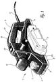
- the hand-held planer 1 shown in Figure 1 has a casing composed of two halves 2, 3, with a detachable cover 4 screwed on to a projecting edge 39 on the outside of casing half 3.
- the casing halves 2, 3 of the casing form a forward-projecting additional handle 8 and also a grip opening 9, into which a switch activator or trigger 15 projects in the usual manner and is used to activate an on/off switch of the planer.
- the trigger 15, as will be described later, can only be moved into the on-position if a safety switch member 20 projecting from the top of the casing has been shifted beforehand.
- a sawdust vent is provided in casing half 3 in the form of a laterally projecting tubular connector 10.
- casing half 3 On the under-side of the casing halves 2, 3, there is a stationary shoe 6 and a front shoe section 5, which can be moved up and down in a known manner to adjust the depth of cut, the height of which can be altered by means of a rotary knob 7.
- a cable 11 for connecting the hand-held planer 1 to a power supply is passed into the casing at its rear end.
- planer 1 is essentially conventional in its interior construction, and therefore only the parts which appear necessary for the explanation of the invention are shown in Figure 2.
- the end of the L shaped lever 26 opposite the lever 23 is pivotally connected by a pin 29 to a link-lever 30 which is bent at its ends and, when the tool is assembled, extends outwards with its middle section parallel to the longitudinal axes of the ;bearing pins 44 and 47, so that its outer end, on which a pivot connection 31 is provided, extends into the region which is covered by the cover 4 as shown in Figure 1.
- the cutter shaft 50 which is carried so that it rotates in the bearing 43.
- the pulley 51 which consists, for example, of free-cutting steel, is non-rotatably attached, so that when driven it is moved in the direction of the arrow F.
- annular slot 53 is formed around its circumference, the side walls of which converge to the base of the slot ( Figure 3).
- a lower section of the brake element 34 extends into the slot 53, and is curved to match the annular slot 53. In the condition shown in Figure 2, where the safety element 21 is in the safety position, the lower section of the brake element 34 is pushed by the force of the spring 36 into braking frictional engagement with the side walls of the annular slot 53, thus preventing rotation of the cutter shaft 50.
Landscapes
- Life Sciences & Earth Sciences (AREA)
- Engineering & Computer Science (AREA)
- Mechanical Engineering (AREA)
- Wood Science & Technology (AREA)
- Forests & Forestry (AREA)
- Milling, Drilling, And Turning Of Wood (AREA)
- Harvester Elements (AREA)
- Sawing (AREA)
Claims (9)
- In der Hand zu haltendes Werkzeug mit einem zur Drehung angetriebenen Werkzeug, insbesondere ein Hobel oder eine Kreissäge, mit:
einem Auslöser (15), durch den der Antrieb ein- und ausgeschaltet werden kann,
einem Bremselement (34),
einem Bremsteil (51), das durch den Antrieb zur Drehung angetrieben wird und das in bremsenden Kontakt mit dem Bremselement (34) gebracht werden kann,
einem Sicherungselement (21), das mit dem Auslöser (15) zusammenarbeitet und beweglich ist zwischen einer Sicherungsposition, in welcher der Auslöser (15) nicht bewegt werden kann, um den Antrieb einzuschalten, und einer Freigabeposition, in welcher der Auslöser (15) in eine Position bewegt werden kann, um den Antrieb einzuschalten,
Federmitteln (28), die das Sicherungselement (21) in seine Sicherungsposition drücken, wobei das Sicherungselement (21) in seiner Freigabeposition gehalten wird, wenn sich der Auslöser (15) in seiner Einschalt-Position befindet,
wobei das Sicherungselement (21) mit dem Bremselement (34) mechanisch verbunden ist, so daß das Bremselement ohne Wirkung ist, wenn sich das Sicherungselement in seiner Freigabeposition befindet, und die Abbremsung des Bremsteils (51) bewirkt, wenn sich das Sicherungselement in seiner Sicherungsposition befindet,
dadurch gekennzeichnet, daß
das Bremselement (34) einen festen Körper aufweist, der an einem Ende schwenkbar an einer Achse (37) angebracht ist und an seinem anderen Ende mit dem Sicherungselement (21) verbunden ist, und daß das Bremselement (34), wenn sich das Sicherungselement (21) in seiner Sicherungsposition befindet, in Reibungskontakt mit einer Bremsfläche (53) steht, die auf dem sich drehenden Bremsteil gebildet ist, und daß das Bremselement (34), wenn sich das Sicherungselement in seiner Freigabeposition befindet, von dem Bremsteil (51) gelöst ist. - In der Hand zu haltendes angetriebenes Werkzeug nach Anspruch 1, dadurch gekennzeichnet, daß die Bewegungsrichtung des Sicherungselements (21) zwischen der Sicherungsposition und der Freigabeposition senkrecht zur Bewegungsrichtung (A) des Auslösers (15) verläuft.
- In der Hand zu haltendes angetriebenes Werkzeug nach Anspruch 1 oder 2, dadurch gekennzeichnet, daß das Bremselement (34) durch Federandruck in bremsenden Kontakt gedrückt wird.
- In der Hand zu haltendes angetriebenes Werkzeug nach Anspruch 3, dadurch gekennzeichnet, daß die Bremsfläche (53) auf einer Außenfläche gebildet ist, die konzentrisch zur Drehachse (50) des Bremsteils (51) liegt.
- In der Hand zu haltendes angetriebenes Werkzeug nach Anspruch 4, dadurch gekennzeichnet, daß die Bremsfläche (53) durch eine ringförmige Rille gebildet wird, deren Seitenwände in Richtung auf den Boden der Rille zu zusammenlaufen.
- In der Hand zu haltendes angetriebenes Werkzeug nach Anspruch 4 oder 5, dadurch gekennzeichnet, daß das Bremsteil aus einem zylindrischen Abschnitt (51) besteht, der nichtdrehbar auf einer das Werkzeug tragenden Welle (50) angebracht ist.
- In der Hand zu haltendes angetriebenes Werkzeug nach Anspruch 6, dadurch gekennzeichnet, daß der zylindrische Abschnitt (51) eine Scheibe ist.
- In der Hand zu haltendes angetriebenes Werkzeug nach einem der Ansprüche 4 bis 7, dadurch gekennzeichnet, daß die sich drehende Bremsfläche (53) sich in Längsrichtung des Bremselements (34) bewegt.
- In der Hand zu haltendes angetriebenes Werkzeug nach Anspruch 8, dadurch gekennzeichnet, daß das Bremselement (34) einen der Bremsfläche (53) zugewandten Abschnitt aufweist, der zwischen den Endbereichen des Elements (34) liegt und in Kontakt mit der Bremsfläche (53) kommt und gekrümmt geformt ist, um sich an die Bremsfläche (53) anzupassen.
Applications Claiming Priority (2)
| Application Number | Priority Date | Filing Date | Title |
|---|---|---|---|
| DE4007030A DE4007030A1 (de) | 1990-03-02 | 1990-03-02 | Kraftgetriebene handwerkzeugmaschine mit einem rotierend angetriebenen werkzeug |
| DE4007030 | 1990-03-02 |
Publications (3)
| Publication Number | Publication Date |
|---|---|
| EP0444909A2 EP0444909A2 (de) | 1991-09-04 |
| EP0444909A3 EP0444909A3 (en) | 1991-11-21 |
| EP0444909B1 true EP0444909B1 (de) | 1994-03-30 |
Family
ID=6401534
Family Applications (1)
| Application Number | Title | Priority Date | Filing Date |
|---|---|---|---|
| EP91301609A Expired - Lifetime EP0444909B1 (de) | 1990-03-02 | 1991-02-27 | Kraftangetriebenes Handgerät mit einem rotierenden, angetriebenen Werkzeug |
Country Status (3)
| Country | Link |
|---|---|
| US (1) | US5094000A (de) |
| EP (1) | EP0444909B1 (de) |
| DE (2) | DE4007030A1 (de) |
Families Citing this family (83)
| Publication number | Priority date | Publication date | Assignee | Title |
|---|---|---|---|---|
| DE4120875C2 (de) * | 1991-06-21 | 2000-06-08 | Stihl Maschf Andreas | Motorkettensäge mit im Kettenraddeckel integrierter Bremsvorrichtung |
| DE4134768A1 (de) * | 1991-10-22 | 1993-04-29 | Bosch Gmbh Robert | Handhobelmaschine |
| US5237752A (en) * | 1992-02-20 | 1993-08-24 | Daryl Maseck | Movable control-handle for chainsaw |
| EP0558253A1 (de) * | 1992-02-28 | 1993-09-01 | Black & Decker Inc. | Staubsammeln |
| US5463816A (en) * | 1994-05-10 | 1995-11-07 | Ryobi North America | Portable planer with adjustable chip deflector |
| US5778747A (en) * | 1996-11-21 | 1998-07-14 | Rexon Industrial Corp., Ltd. | Power saw having an ergonomically-designed handle and safety switch |
| US6091035A (en) | 1998-08-14 | 2000-07-18 | Black & Decker, Inc. | Lockout mechanism for power tool |
| US6057518A (en) * | 1998-08-14 | 2000-05-02 | Black & Decker, Inc. | Lockout mechanism for power tool |
| US8061245B2 (en) | 2000-09-29 | 2011-11-22 | Sd3, Llc | Safety methods for use in power equipment |
| US7827890B2 (en) | 2004-01-29 | 2010-11-09 | Sd3, Llc | Table saws with safety systems and systems to mount and index attachments |
| US7024975B2 (en) | 2000-08-14 | 2006-04-11 | Sd3, Llc | Brake mechanism for power equipment |
| US7098800B2 (en) | 2003-03-05 | 2006-08-29 | Sd3, Llc | Retraction system and motor position for use with safety systems for power equipment |
| US20050041359A1 (en) | 2003-08-20 | 2005-02-24 | Gass Stephen F. | Motion detecting system for use in a safety system for power equipment |
| US7377199B2 (en) | 2000-09-29 | 2008-05-27 | Sd3, Llc | Contact detection system for power equipment |
| US7836804B2 (en) | 2003-08-20 | 2010-11-23 | Sd3, Llc | Woodworking machines with overmolded arbors |
| US7712403B2 (en) | 2001-07-03 | 2010-05-11 | Sd3, Llc | Actuators for use in fast-acting safety systems |
| US7536238B2 (en) | 2003-12-31 | 2009-05-19 | Sd3, Llc | Detection systems for power equipment |
| US6857345B2 (en) | 2000-08-14 | 2005-02-22 | Sd3, Llc | Brake positioning system |
| US7509899B2 (en) | 2000-08-14 | 2009-03-31 | Sd3, Llc | Retraction system for use in power equipment |
| US9724840B2 (en) * | 1999-10-01 | 2017-08-08 | Sd3, Llc | Safety systems for power equipment |
| US7210383B2 (en) | 2000-08-14 | 2007-05-01 | Sd3, Llc | Detection system for power equipment |
| US7171879B2 (en) | 2001-07-02 | 2007-02-06 | Sd3, Llc | Discrete proximity detection system |
| US20030056853A1 (en) | 2001-09-21 | 2003-03-27 | Gass Stephen F. | Router with improved safety system |
| US7137326B2 (en) | 2000-08-14 | 2006-11-21 | Sd3, Llc | Translation stop for use in power equipment |
| US7610836B2 (en) | 2000-08-14 | 2009-11-03 | Sd3, Llc | Replaceable brake mechanism for power equipment |
| US9927796B2 (en) | 2001-05-17 | 2018-03-27 | Sawstop Holding Llc | Band saw with improved safety system |
| US7707920B2 (en) | 2003-12-31 | 2010-05-04 | Sd3, Llc | Table saws with safety systems |
| US8459157B2 (en) | 2003-12-31 | 2013-06-11 | Sd3, Llc | Brake cartridges and mounting systems for brake cartridges |
| US7055417B1 (en) | 1999-10-01 | 2006-06-06 | Sd3, Llc | Safety system for power equipment |
| US7225712B2 (en) | 2000-08-14 | 2007-06-05 | Sd3, Llc | Motion detecting system for use in a safety system for power equipment |
| US7290472B2 (en) | 2002-01-14 | 2007-11-06 | Sd3, Llc | Miter saw with improved safety system |
| US7077039B2 (en) | 2001-11-13 | 2006-07-18 | Sd3, Llc | Detection system for power equipment |
| US7231856B2 (en) | 2001-06-13 | 2007-06-19 | Sd3, Llc | Apparatus and method for detecting dangerous conditions in power equipment |
| US20020017179A1 (en) | 2000-08-14 | 2002-02-14 | Gass Stephen F. | Miter saw with improved safety system |
| US7472634B2 (en) | 2003-08-20 | 2009-01-06 | Sd3, Llc | Woodworking machines with overmolded arbors |
| US7197969B2 (en) | 2001-09-24 | 2007-04-03 | Sd3, Llc | Logic control with test mode for fast-acting safety system |
| US7000514B2 (en) | 2001-07-27 | 2006-02-21 | Sd3, Llc | Safety systems for band saws |
| US7353737B2 (en) | 2001-08-13 | 2008-04-08 | Sd3, Llc | Miter saw with improved safety system |
| US7308843B2 (en) | 2000-08-14 | 2007-12-18 | Sd3, Llc | Spring-biased brake mechanism for power equipment |
| US7100483B2 (en) | 2000-08-14 | 2006-09-05 | Sd3, Llc | Firing subsystem for use in a fast-acting safety system |
| US7284467B2 (en) | 2000-08-14 | 2007-10-23 | Sd3, Llc | Apparatus and method for detecting dangerous conditions in power equipment |
| US8065943B2 (en) | 2000-09-18 | 2011-11-29 | Sd3, Llc | Translation stop for use in power equipment |
| US7350445B2 (en) | 2003-08-20 | 2008-04-01 | Sd3, Llc | Brake cartridge for power equipment |
| US7350444B2 (en) * | 2000-08-14 | 2008-04-01 | Sd3, Llc | Table saw with improved safety system |
| US7600455B2 (en) | 2000-08-14 | 2009-10-13 | Sd3, Llc | Logic control for fast-acting safety system |
| US7481140B2 (en) | 2005-04-15 | 2009-01-27 | Sd3, Llc | Detection systems for power equipment |
| US6994004B2 (en) | 2000-09-29 | 2006-02-07 | Sd3, Llc | Table saw with improved safety system |
| US6633046B1 (en) * | 2000-04-19 | 2003-10-14 | Applied Materials, Inc. | Method and apparatus for detecting that two moveable members are correctly positioned relatively to one another |
| US7856724B2 (en) * | 2000-08-17 | 2010-12-28 | Hilti Aktiengesellschaft | Electrical power tool with a rotatable working tool |
| DE10040332B4 (de) * | 2000-08-17 | 2009-03-05 | Hilti Aktiengesellschaft | Elektrowerkzeug mit rotierend angetriebenem Werkzeug und einer Bremsvorrichtung |
| US7168502B2 (en) * | 2000-08-17 | 2007-01-30 | Hilti Aktiengesellschaft | Electric power tool with locking mechanism |
| DE10048675A1 (de) * | 2000-09-30 | 2002-04-18 | Festool Gmbh | Handwerkzeugmaschine |
| DE20104536U1 (de) * | 2001-03-16 | 2001-05-23 | Andreas Stihl AG & Co., 71336 Waiblingen | Handgeführtes, tragbares Arbeitsgerät mit Daumenstützen |
| USD495574S1 (en) | 2001-08-24 | 2004-09-07 | Robert Bosch Gmbh | Planer |
| DE20203683U1 (de) * | 2002-03-08 | 2003-07-24 | Robert Bosch Gmbh, 70469 Stuttgart | Handhobelmaschine |
| USD475594S1 (en) | 2002-05-13 | 2003-06-10 | Positec Power Tools (Suzhou) Co., Ltd. | Planer |
| USD492563S1 (en) | 2003-05-27 | 2004-07-06 | Black & Decker Inc. | Belt sander |
| USD509721S1 (en) * | 2003-09-17 | 2005-09-20 | Gmca Pty Limited | Planer |
| USD497298S1 (en) | 2003-12-16 | 2004-10-19 | One World Technologies, Limited | Belt sander |
| AU156895S (en) * | 2004-02-18 | 2004-11-15 | Bosch Gmbh Robert | Planer |
| USD501775S1 (en) * | 2004-03-09 | 2005-02-15 | One World Technologies, Limited | Hand planer |
| US20050284543A1 (en) * | 2004-06-23 | 2005-12-29 | One World Technologies Limited | Pre-directing insert for a bi-directional exhausting handheld planer |
| USD508833S1 (en) | 2004-09-24 | 2005-08-30 | One World Technologies Limited | Planer |
| AU307350S (en) * | 2005-10-26 | 2006-06-08 | Power Box Ag | A belt sander |
| USD529357S1 (en) * | 2005-11-02 | 2006-10-03 | Chervon International Trading Co., Ltd. | Planer |
| USD529775S1 (en) | 2005-11-30 | 2006-10-10 | Black & Decker Inc. | Belt sander |
| USD598261S1 (en) * | 2006-05-02 | 2009-08-18 | Gmca Pty Limited | Powered planer |
| USD559641S1 (en) * | 2006-08-07 | 2008-01-15 | Hitachi Koki Co., Ltd. | Portable electric sander |
| GB0710034D0 (en) * | 2007-05-25 | 2007-07-04 | Gmca Pty Ltd | Improved planer |
| USD570173S1 (en) * | 2007-08-23 | 2008-06-03 | Black & Decker Inc. | Belt sander |
| USD570661S1 (en) * | 2007-08-23 | 2008-06-10 | Black & Decker Inc. | Belt sander |
| USD607291S1 (en) * | 2008-05-23 | 2010-01-05 | Black & Decker Inc. | Planer |
| GB2460415A (en) * | 2008-05-28 | 2009-12-02 | Black & Decker Inc | Hand held powered planer with handle attached at one end to housing |
| CN102271882A (zh) * | 2008-10-13 | 2011-12-07 | 彼得·艾特拉吉克 | 手持式电动木刨床的改良 |
| USD601874S1 (en) * | 2009-01-09 | 2009-10-13 | Makita Corporation | Portable electric planer |
| USD603673S1 (en) * | 2009-05-05 | 2009-11-10 | Black & Decker Inc. | Planer |
| DE112010005800T5 (de) * | 2010-08-11 | 2013-06-13 | Bosch Power Tools (China) Co., Ltd. | Elektrohandwerkzeug mit verbesserter Bremsanordnung |
| US8723060B2 (en) * | 2011-12-21 | 2014-05-13 | Robert Bosch Tool Corporation | Method and mechanism for power tool lock-off |
| DE102012218197A1 (de) * | 2012-05-04 | 2013-11-07 | Robert Bosch Gmbh | Werkzeugmaschinenbremsvorrichtung |
| DE102012218071A1 (de) * | 2012-10-03 | 2014-06-12 | Hilti Aktiengesellschaft | Handgeführtes Werkzeuggerät mit einer Bremsvorrichtung zum Bremsen eines Bearbeitungswerkzeuges |
| US10118308B2 (en) | 2013-10-17 | 2018-11-06 | Sawstop Holding Llc | Systems to mount and index riving knives and spreaders in table saws |
| DE102014212160A1 (de) * | 2014-06-25 | 2015-12-31 | Robert Bosch Gmbh | Tragbare Werkzeugmaschine |
| EP4292787A1 (de) | 2022-04-25 | 2023-12-20 | Milwaukee Electric Tool Corporation | Handhobelwerkzeug |
Family Cites Families (11)
| Publication number | Priority date | Publication date | Assignee | Title |
|---|---|---|---|---|
| DE890419C (de) * | 1949-10-30 | 1953-09-17 | Karl M Reich Fa | Elektrisch betriebene tragbare Hobelmaschine |
| US3074517A (en) * | 1959-09-02 | 1963-01-22 | Kohll Roland | Adjustement device for electromechanical brakes |
| US3313379A (en) * | 1966-04-04 | 1967-04-11 | Clark Equipment Co | Brake |
| US3679027A (en) * | 1970-07-23 | 1972-07-25 | Case Co J I | Braking method and apparatus |
| DE3024561A1 (de) * | 1980-06-28 | 1982-01-21 | Robert Bosch Gmbh, 7000 Stuttgart | Handwerkzeugmaschine mit elektromotorischem antrieb |
| US4335514A (en) * | 1980-08-08 | 1982-06-22 | Black & Decker Inc. | Switch-brake interlock for chain saw |
| US4433710A (en) * | 1981-10-28 | 1984-02-28 | Posta Antonio D | Power planing tool |
| US4487294A (en) * | 1982-03-16 | 1984-12-11 | Geeck Iii Joseph S | Brake assembly |
| JPS60152406U (ja) * | 1984-03-21 | 1985-10-11 | 株式会社 マキタ電機製作所 | チエ−ンソ−における安全装置 |
| DE3607376A1 (de) * | 1986-03-06 | 1987-09-10 | Metabowerke Kg | Tragbare motorkettensaege mit einer reibungsbremse zum abbremsen der saegekette |
| DE8908924U1 (de) * | 1989-07-22 | 1989-09-14 | Gardena Kress + Kastner Gmbh, 7900 Ulm | Sicherheitsschalteinrichtung für Elektrogeräte, insbesondere elektrisch angetriebene Handarbeitswerkzeuge |
-
1990
- 1990-03-02 DE DE4007030A patent/DE4007030A1/de not_active Withdrawn
-
1991
- 1991-02-27 EP EP91301609A patent/EP0444909B1/de not_active Expired - Lifetime
- 1991-02-27 DE DE69101507T patent/DE69101507T2/de not_active Expired - Lifetime
- 1991-03-01 US US07/663,384 patent/US5094000A/en not_active Expired - Lifetime
Also Published As
| Publication number | Publication date |
|---|---|
| EP0444909A2 (de) | 1991-09-04 |
| DE69101507T2 (de) | 1994-07-14 |
| DE4007030A1 (de) | 1991-09-05 |
| US5094000A (en) | 1992-03-10 |
| EP0444909A3 (en) | 1991-11-21 |
| DE69101507D1 (de) | 1994-05-05 |
Similar Documents
| Publication | Publication Date | Title |
|---|---|---|
| EP0444909B1 (de) | Kraftangetriebenes Handgerät mit einem rotierenden, angetriebenen Werkzeug | |
| US5685080A (en) | Battery powered chain saw | |
| US7856724B2 (en) | Electrical power tool with a rotatable working tool | |
| USRE37832E1 (en) | Electromotive chain saw | |
| US5832614A (en) | Remote lower guard lift lever mechanism for circular saws | |
| US5480009A (en) | Brake system with two independent mechanical brakes | |
| JP4729159B2 (ja) | 手持ち式の電動複合ハンマ装置 | |
| JP3338543B2 (ja) | ヘッジトリマ | |
| US4449062A (en) | Safety arrangement for a powered tool or implement | |
| US5915795A (en) | Chain saw braking device | |
| US4455811A (en) | Bail attachment lawnmower zone start control | |
| EP0335700B1 (de) | Kombination von Schalter und Sperrvorrichtung | |
| EP1504659B1 (de) | Abriegelungsmechanismus für eine schwenkbare Griffanordnung eines Kraftwerkzeugs | |
| EP0333179B1 (de) | Triggerschalter | |
| JP7827564B2 (ja) | ケーブルカッター及びそのリングアタッチメント | |
| US4882844A (en) | Chain saw safety brake apparatus | |
| US4922069A (en) | Electrical control switch mechanism | |
| CA2151643A1 (en) | Cutting device | |
| JP2005132113A (ja) | 往復動鋸のブレード留め具 | |
| CN112548791B (zh) | 研磨机 | |
| EP1212935B1 (de) | Heckenschere | |
| FR2607420A1 (fr) | Outil electrique de serrage de vis | |
| US20020026717A1 (en) | Electrical power tool with a rotatable working tool | |
| GB2325388A (en) | Dual-clearance activation device for tools | |
| KR102807244B1 (ko) | 브레이크 시스템을 구비한 체인 톱 |
Legal Events
| Date | Code | Title | Description |
|---|---|---|---|
| PUAI | Public reference made under article 153(3) epc to a published international application that has entered the european phase |
Free format text: ORIGINAL CODE: 0009012 |
|
| AK | Designated contracting states |
Kind code of ref document: A2 Designated state(s): CH DE FR GB IT LI |
|
| PUAL | Search report despatched |
Free format text: ORIGINAL CODE: 0009013 |
|
| AK | Designated contracting states |
Kind code of ref document: A3 Designated state(s): CH DE FR GB IT LI |
|
| 17P | Request for examination filed |
Effective date: 19911213 |
|
| 17Q | First examination report despatched |
Effective date: 19921109 |
|
| GRAA | (expected) grant |
Free format text: ORIGINAL CODE: 0009210 |
|
| AK | Designated contracting states |
Kind code of ref document: B1 Designated state(s): CH DE FR GB IT LI |
|
| REF | Corresponds to: |
Ref document number: 69101507 Country of ref document: DE Date of ref document: 19940505 |
|
| ET | Fr: translation filed | ||
| ITF | It: translation for a ep patent filed | ||
| PLBE | No opposition filed within time limit |
Free format text: ORIGINAL CODE: 0009261 |
|
| STAA | Information on the status of an ep patent application or granted ep patent |
Free format text: STATUS: NO OPPOSITION FILED WITHIN TIME LIMIT |
|
| 26N | No opposition filed | ||
| PGFP | Annual fee paid to national office [announced via postgrant information from national office to epo] |
Ref country code: FR Payment date: 19960118 Year of fee payment: 6 |
|
| PG25 | Lapsed in a contracting state [announced via postgrant information from national office to epo] |
Ref country code: FR Effective date: 19971030 |
|
| REG | Reference to a national code |
Ref country code: FR Ref legal event code: ST |
|
| REG | Reference to a national code |
Ref country code: GB Ref legal event code: IF02 |
|
| PG25 | Lapsed in a contracting state [announced via postgrant information from national office to epo] |
Ref country code: IT Free format text: LAPSE BECAUSE OF NON-PAYMENT OF DUE FEES;WARNING: LAPSES OF ITALIAN PATENTS WITH EFFECTIVE DATE BEFORE 2007 MAY HAVE OCCURRED AT ANY TIME BEFORE 2007. THE CORRECT EFFECTIVE DATE MAY BE DIFFERENT FROM THE ONE RECORDED. Effective date: 20050227 |
|
| PGFP | Annual fee paid to national office [announced via postgrant information from national office to epo] |
Ref country code: CH Payment date: 20080228 Year of fee payment: 18 |
|
| REG | Reference to a national code |
Ref country code: CH Ref legal event code: PL |
|
| PG25 | Lapsed in a contracting state [announced via postgrant information from national office to epo] |
Ref country code: LI Free format text: LAPSE BECAUSE OF NON-PAYMENT OF DUE FEES Effective date: 20090228 Ref country code: CH Free format text: LAPSE BECAUSE OF NON-PAYMENT OF DUE FEES Effective date: 20090228 |
|
| PGFP | Annual fee paid to national office [announced via postgrant information from national office to epo] |
Ref country code: GB Payment date: 20100224 Year of fee payment: 20 Ref country code: DE Payment date: 20100226 Year of fee payment: 20 |
|
| REG | Reference to a national code |
Ref country code: DE Ref legal event code: R071 Ref document number: 69101507 Country of ref document: DE |
|
| REG | Reference to a national code |
Ref country code: GB Ref legal event code: PE20 Expiry date: 20110226 |
|
| PG25 | Lapsed in a contracting state [announced via postgrant information from national office to epo] |
Ref country code: GB Free format text: LAPSE BECAUSE OF EXPIRATION OF PROTECTION Effective date: 20110226 |
|
| PG25 | Lapsed in a contracting state [announced via postgrant information from national office to epo] |
Ref country code: DE Free format text: LAPSE BECAUSE OF EXPIRATION OF PROTECTION Effective date: 20110227 |