EP0444929A2 - Power source control system for automobile telephone - Google Patents
Power source control system for automobile telephone Download PDFInfo
- Publication number
- EP0444929A2 EP0444929A2 EP91301643A EP91301643A EP0444929A2 EP 0444929 A2 EP0444929 A2 EP 0444929A2 EP 91301643 A EP91301643 A EP 91301643A EP 91301643 A EP91301643 A EP 91301643A EP 0444929 A2 EP0444929 A2 EP 0444929A2
- Authority
- EP
- European Patent Office
- Prior art keywords
- telephone
- power
- automobile
- state
- power source
- Prior art date
- Legal status (The legal status is an assumption and is not a legal conclusion. Google has not performed a legal analysis and makes no representation as to the accuracy of the status listed.)
- Granted
Links
Images


Classifications
-
- H—ELECTRICITY
- H04—ELECTRIC COMMUNICATION TECHNIQUE
- H04W—WIRELESS COMMUNICATION NETWORKS
- H04W52/00—Power management, e.g. Transmission Power Control [TPC] or power classes
- H04W52/02—Power saving arrangements
- H04W52/0209—Power saving arrangements in terminal devices
- H04W52/0261—Power saving arrangements in terminal devices managing power supply demand, e.g. depending on battery level
- H04W52/0296—Power saving arrangements in terminal devices managing power supply demand, e.g. depending on battery level switching to a backup power supply
-
- Y—GENERAL TAGGING OF NEW TECHNOLOGICAL DEVELOPMENTS; GENERAL TAGGING OF CROSS-SECTIONAL TECHNOLOGIES SPANNING OVER SEVERAL SECTIONS OF THE IPC; TECHNICAL SUBJECTS COVERED BY FORMER USPC CROSS-REFERENCE ART COLLECTIONS [XRACs] AND DIGESTS
- Y02—TECHNOLOGIES OR APPLICATIONS FOR MITIGATION OR ADAPTATION AGAINST CLIMATE CHANGE
- Y02D—CLIMATE CHANGE MITIGATION TECHNOLOGIES IN INFORMATION AND COMMUNICATION TECHNOLOGIES [ICT], I.E. INFORMATION AND COMMUNICATION TECHNOLOGIES AIMING AT THE REDUCTION OF THEIR OWN ENERGY USE
- Y02D30/00—Reducing energy consumption in communication networks
- Y02D30/70—Reducing energy consumption in communication networks in wireless communication networks
Definitions
- the present invention relates to a power source control system for an on-board telephone for automobile use and, more particularly, to a power source control system which allows such an on-board telephone to be used even when the engine of an automobile carrying it therewith is in a halt, with no regard to the configuration of an ignition switch.
- a telephone mounted on an automobile and powered by a power source, or battery, of the automobile belongs to a family of mobile radio telephones which are extensively used today.
- An automobile has an ignition switch which is operated by a key inserted in a key slot.
- Ignition switches may generally classified into two tapes, i. e., a four-position tape ignition switch having engine OFF, accessory, engine ON and engine start positions, and a three-position tape ignition switch having engine OFF, engine ON and engine start positions.
- the accessory position allows an on-board stereo, telephone and other accessories to be used while the engine is in a halt.
- the accessory position has to be used with care since it causes the accessories to consume the power fed from the power source, or battery, of the vehicle.
- the key may be operated to actuate the ignition switch to the accessory position or to the engine ON position or to actuate it to the engine start position to start the engine and then to the engine ON position.
- the power switch of the telephone is turned on or is held in an ON state, power is fed from the battery to the telephone.
- the power switch of the telephone is turned off or when the key is operated to bring the ignition switch to the engine OFF position, the supply of power to the telephone is interrupted.
- the automobile on which the conventional vehicle telephone is mounted has the three-position ignition switch which lacks the accessory position.
- the telephone is usable only when the key is operated to bring the ignition switch to the engine start position to start the engine and then to the engine ON position.
- the power switch of the telephone is turned on or held in an ON state, power is fed from the battery to the telephone.
- the power switch is turned off or when the key of the automobile is operated to bring the ignition switch to the engine OFF position, the power supply to the telephone is interrupted.
- the drawback with the conventional power source control system for an automobile telephone is that when the vehicle carrying the telephone therewith has the three-position ignition switch, power cannot be fed to the telephone when the ignition of the automobile is in an OFF state. Stated another way, the on-board telephone cannot be used unless the ignition switch is brought to the engine start position to start the engine each time.
- the supply of power from the power source to the telephone is controlled on the basis of at least one of the state of a power switch of the telephone and whether or not a conversation is under way on the telephone, with no regard to an ON/OFF state of an ignition of the automobile.
- a power supply control system for a telephone which is mounted on an automobile and having a power source and a power switch to which power is supplied from a power source of the automobile has a connector for connecting the telephone and the power source of the automobile.
- a controller controls the supply of power from the power source of the automobile to the telephone by driving the connector on the basis of the ON/OFF state of an ignition of the automobile, the state of the power switch, and whether or not a conversation is under way on the telephone.
- a power source control section included in an automobile telephone and implemented with a preferred embodiment of the present invention is shown together with devices associated therewith.
- the power source control section generally 10, is connected to an ignition line 12, a power switch 14, and a relay 16.
- the state of an ignition of a vehicle on which the telephone is mounted is represented by a signal which is fed to the control section 10 over the ignition line.
- the relay 16 connects a power source or battery (not shown) mounted on the vehicle to the telephone via terminals 18 and 20 which are connected to the battery and the telephone, respectively.
- the control section 10 sends a control signal CONT to the relay 16 to instruct it whether or not to connect the power source and battery terminals 18 and 20, as will be described later specifically.
- the relay 16 When the control signal CONT is in a high level, the relay 16 connects the terminals 18 and 20 to feed power to the on-board telephone. As the control signal CONT goes low, the relay 16 disconnects the terminals 18 and 20 from each other. Implemented as a push switch, the power switch 14 is closed while it is pushed and inverts the state of power supply to the telephone every time it is pushed.
- the power source control section 10 has a CPU or similar processor 22 and peripheral circuitry associated therewith.
- the CPU 22 may be implemented by ⁇ PD70008 or ⁇ PD70108 available from NEC.
- the peripheral circuitry is constantly powered by the automobile power source 18 while the CPU 22 is powered through the terminal 20. More specifically, the CPU 22 starts operating on the connection of the telephone power source terminal 20 to the battery terminal 18.
- the peripheral circuitry includes an inverter gate 24 whose input is connected to the ignition line 12.
- a NAND gate 26 is connected at one input thereof to the output of the inverter gate 24.
- An inverter grate 28 is connected to the output of the NAND gate 26.
- An inverter gate 30 is connected at the input thereof to the power switch 14 and at the output thereof to a clock input CK of a D flip-flop 32.
- the D flip-flop 32 has an inverting output Q thereof connected to one input of a NAND gate 34.
- the NAND gate 34 feeds an output thereof to the relay 16 as a control signal CONT.
- the inverting output Q of the flip-flop 32 is also connected to a data input D of the flip-flop 32.
- An n-p-n transistor 36 has a base connected to the output of the inverter gate 24, a collector connector to the CPU 22, and an emitter connected to ground.
- An n-p-n transistor 38 has a base connected to the non-inverting output Q of the D flip-flop 32, a collector connected to the CPU 22, and an emitter connected to ground.
- an n-p-n transistor 40 has a base connected to the CPU 22, a collector connected to the other inputs of the NAND gates 26 and 34, and emitter connected to ground.
- the input of the inverter grate 30 is connected to the automobile battery terminal 18 via a pull-up resistor 42.
- the reset input R of the D flip-flop 32 is connected to ground via a resistor 44 and to the output of the inverter gate 28 via a capacitor 46.
- the set input S of the D flip-flop 32 is connected to ground via a resistor 48 and to the output of the NAND gate 26 via a capacitor 50.
- the collector of the transistor 40 is also connected to the automobile power source 18 via a pull-up resistor 52.
- the collectors of the transistors 36 and 38 are connected to the telephone power source terminal 20 via pull-up resistors 54 and 56, respectively.
- the CPU 22 feeds a signal to the base of the transistor 40 on the basis of the states of the collectors of the transistors 36 and 38 and whether or not the telephone is in use, according to a specific procedure shown in Fig. 2.
- the low level on the inverting output Q of the flip-flop 32 causes the NAND gate 34 to feed a high-level signal to the relay 16 as a control signal CONT, whereby the telephone power source terminal 20 is connected to the battery terminal 18 and, therefore, the CPU 22 are activated.
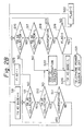
- the CPU 22 executes steps S1 to S4 shown in Fig. 2 and then an iterative loop of steps S5 to S7.
- the CPU 22 feeds a low-level signal to the base of the transistor 40.
- the inverting output Q of the D flip-flop 32 is inverted to a high level.
- the NAND gate 34 delivers a low-level signal to the relay 16 as a control signal CONT and thereby turns off the telephone.
- the inverting output Q of the flip-flop is inverted to a high level.
- the collector of the transistor 40 is in a low level, the output of the NAND gate 34 remains in a high level.
- the CPU 22 detects the change of the collector of the transistor 38 from a low level to a high level.
- the CPU 22 causes the base of the transistor 40 into a low level and thereby the output of the NAND gate 34 into a low level. As a result, the telephone is turned off.
- the telephone is also turned on and off in response to the change of the ignition from OFF to ON and from ON to OFF, as follows.
- the output of the inverter gate 28 goes low with the result that one high-level pulse is fed to the reset input R of the D flip-flop 32.
- This pulse causes the inverting output Q of the D flip-flop 32 into a low level and thereby connects the telephone power source terminal 20 to the battery terminal 18, whereby the CPU 22 is powered.
- the CPU 22 executes the loop of steps S5 to S7 by way of the steps S1 to S4.
- a low level is fed to the base of the transistor 40, so that the state of the D flip-flop 32 does not change.
- the output of the NAND gate 26 goes low.
- the embodiment holds the telephone in the ON state until the conversation ends, as follows.
- step S8 the CPU 22 has already entered an iterative loop of steps S9 to S11 by way of a step S8.
- the inverting output Q of the D flip-flop 32 is in a low level.
- step S8 the CPU 22 feeds a high-level signal to the base of the transistor 40. In this condition, when the ignition line 12 goes low, the output of the NAND gate 26 remains in a high level since the collector of the transistor 40 is in a low level.
- the collector of the transistor 36 goes low with the result that the CPU 22 executes a step S25 on the basis of the result of decision in the step S9 and then enters a loop of steps S16 to S18.
- This loop is repetitively executed so long as the power switch 14 is not pushed during conversation.
- the CPU 22 advances to a step S26 by way of the step S18 and a step S19, i. e. , it feeds a low level signal to the base of the transistor 40.
- the output of the NAND gate 26 goes low to turn the output of the inverter gate 28 from low to high to thereby feed one high-level pulse to the reset input R of the D flip-flop 32, whereby the telephone is turned off.
- the telephone When it is desired to turn off the telephone by the power switch 14 while a conversation is under way, the telephone is turned off after end-of-conversation processing, as follows.
- the CPU 22 is executing the iterative loop of steps S9 to S11.
- the power switch 14 is pushed once, the inverting output Q of the D flip-flop 32 goes high.
- the CPU 22 executes a step S20, i. e. , end-of-conversation processing on the basis of the result of decision in the step S10.
- the CPU 22 changes the base of the transistor 40 from a high level to a low level, step S20.
- the output of the NAND gate 34 goes low to turn off the telephone.
- the present invention provides a power source control system for an automobile telephone which controls the supply of power to the telephone by a power switch with no regard to the state of an ignition of an automobile on which the telephone is mounted. Therefore, whether the ignition switch has an accessory position or not, the telephone can be used even when the engine of the automobile is in a halt and, therefore, achieves unprecedented freedom. Further, the supply of power to the telephone is automatically set up on the change of the ignition from OFF to ON and is automatically interrupted on the change thereof from ON to OFF. The user of the telephone, therefore, does not have to turn the power switch on and off each time.
Landscapes
- Engineering & Computer Science (AREA)
- Computer Networks & Wireless Communication (AREA)
- Signal Processing (AREA)
- Mobile Radio Communication Systems (AREA)
- Fittings On The Vehicle Exterior For Carrying Loads, And Devices For Holding Or Mounting Articles (AREA)
Abstract
Description
- The present invention relates to a power source control system for an on-board telephone for automobile use and, more particularly, to a power source control system which allows such an on-board telephone to be used even when the engine of an automobile carrying it therewith is in a halt, with no regard to the configuration of an ignition switch.
- A telephone mounted on an automobile and powered by a power source, or battery, of the automobile belongs to a family of mobile radio telephones which are extensively used today. An automobile has an ignition switch which is operated by a key inserted in a key slot. Ignition switches may generally classified into two tapes, i. e., a four-position tape ignition switch having engine OFF, accessory, engine ON and engine start positions, and a three-position tape ignition switch having engine OFF, engine ON and engine start positions. When the ignition switch is brought to the engine start position, the engine of the automobile starts operating. The accessory position allows an on-board stereo, telephone and other accessories to be used while the engine is in a halt. The accessory position has to be used with care since it causes the accessories to consume the power fed from the power source, or battery, of the vehicle.
- Assume that a conventional automobile telephone is mounted on an automobile of the tape having the four-position ignition switch which includes the accessory position. Then, to use the on-board telephone, the key may be operated to actuate the ignition switch to the accessory position or to the engine ON position or to actuate it to the engine start position to start the engine and then to the engine ON position. When the power switch of the telephone is turned on or is held in an ON state, power is fed from the battery to the telephone. When the power switch of the telephone is turned off or when the key is operated to bring the ignition switch to the engine OFF position, the supply of power to the telephone is interrupted.
- On the other hand, assume that the automobile on which the conventional vehicle telephone is mounted has the three-position ignition switch which lacks the accessory position. In this case, the telephone is usable only when the key is operated to bring the ignition switch to the engine start position to start the engine and then to the engine ON position. In this condition, when the power switch of the telephone is turned on or held in an ON state, power is fed from the battery to the telephone. When the power switch is turned off or when the key of the automobile is operated to bring the ignition switch to the engine OFF position, the power supply to the telephone is interrupted.
- As stated above, the drawback with the conventional power source control system for an automobile telephone is that when the vehicle carrying the telephone therewith has the three-position ignition switch, power cannot be fed to the telephone when the ignition of the automobile is in an OFF state. Stated another way, the on-board telephone cannot be used unless the ignition switch is brought to the engine start position to start the engine each time.
- It is therefore an object of the present invention to provide a power source control system for an automobile telephone which, whether the ignition switch of a automobile carrying the telephone therewith has an accessory position or not, allows the telephone to be used even when the engine of the automobile is not operated.
- It is another object of the present invention to provide a generally improved power source control system for an automobile telephone.
- In accordance with the present invention, in a power source control system for a telephone mounted on an automobile and supplied with power from a power source of the automobile, the supply of power from the power source to the telephone is controlled on the basis of at least one of the state of a power switch of the telephone and whether or not a conversation is under way on the telephone, with no regard to an ON/OFF state of an ignition of the automobile.
- Also, in accordance with the present invention, a power supply control system for a telephone which is mounted on an automobile and having a power source and a power switch to which power is supplied from a power source of the automobile has a connector for connecting the telephone and the power source of the automobile. A controller controls the supply of power from the power source of the automobile to the telephone by driving the connector on the basis of the ON/OFF state of an ignition of the automobile, the state of the power switch, and whether or not a conversation is under way on the telephone.
- The above and other objects, features and advantages of the present invention will become more apparent from the following detailed description taken with the accompanying drawings in which:
- Fig. 1 is a block diagram schematically showing a power source control section of an automobile vehicle telephone and devices associated therewith to which a power source control system embodying the present invention is applied; and
- Fig. 2 is a flowchart demonstrating a specific operation of a CPU included in the power source control section.
- Referring to Fig. 1 of the drawings, a power source control section included in an automobile telephone and implemented with a preferred embodiment of the present invention is shown together with devices associated therewith. The power source control section, generally 10, is connected to an
ignition line 12, apower switch 14, and arelay 16. The state of an ignition of a vehicle on which the telephone is mounted is represented by a signal which is fed to the control section 10 over the ignition line. Therelay 16 connects a power source or battery (not shown) mounted on the vehicle to the telephone viaterminals relay 16 to instruct it whether or not to connect the power source andbattery terminals relay 16 connects theterminals relay 16 disconnects theterminals power switch 14 is closed while it is pushed and inverts the state of power supply to the telephone every time it is pushed. - The power source control section 10 has a CPU or
similar processor 22 and peripheral circuitry associated therewith. TheCPU 22 may be implemented by µPD70008 or µPD70108 available from NEC. The peripheral circuitry is constantly powered by theautomobile power source 18 while theCPU 22 is powered through theterminal 20. More specifically, theCPU 22 starts operating on the connection of the telephonepower source terminal 20 to thebattery terminal 18. - The peripheral circuitry includes an
inverter gate 24 whose input is connected to theignition line 12. A NANDgate 26 is connected at one input thereof to the output of theinverter gate 24. Aninverter grate 28 is connected to the output of theNAND gate 26. Aninverter gate 30 is connected at the input thereof to thepower switch 14 and at the output thereof to a clock input CK of a D flip-flop 32. The D flip-flop 32 has an inverting outputQ thereof connected to one input of aNAND gate 34. The NANDgate 34 feeds an output thereof to therelay 16 as a control signal CONT. The inverting outputQ of the flip-flop 32 is also connected to a data input D of the flip-flop 32. Ann-p-n transistor 36 has a base connected to the output of theinverter gate 24, a collector connector to theCPU 22, and an emitter connected to ground. Ann-p-n transistor 38 has a base connected to the non-inverting output Q of the D flip-flop 32, a collector connected to theCPU 22, and an emitter connected to ground. Further, ann-p-n transistor 40 has a base connected to theCPU 22, a collector connected to the other inputs of theNAND gates inverter grate 30 is connected to theautomobile battery terminal 18 via a pull-up resistor 42. The reset input R of the D flip-flop 32 is connected to ground via aresistor 44 and to the output of theinverter gate 28 via acapacitor 46. The set input S of the D flip-flop 32 is connected to ground via aresistor 48 and to the output of theNAND gate 26 via a capacitor 50. The collector of thetransistor 40 is also connected to theautomobile power source 18 via a pull-up resistor 52. The collectors of thetransistors power source terminal 20 via pull-up resistors - The
CPU 22 feeds a signal to the base of thetransistor 40 on the basis of the states of the collectors of thetransistors - The operation of the power source control circuit 10 will be described with reference also made to Fig. 2.
- First, how the telephone is turned on and off by the
power switch 14 with no regard to the state of the ignition will be described. Assume that the telephone is in an OFF state, i. e., theterminal 20 is connected to thebattery terminal 18, and theignition line 12 is in a high level. Then, as thepower switch 14 is pushed once, one high-level pulse is fed to the clock input CK of the D flip-flop 32 via theinverter gate 30. In response, the inverting outputQ of the D flip-flop 3 2 goes low despite that the data input D of the flip-flop 32 is in a high level. The low level on the inverting outputQ of the flip-flop 32 causes theNAND gate 34 to feed a high-level signal to therelay 16 as a control signal CONT, whereby the telephonepower source terminal 20 is connected to thebattery terminal 18 and, therefore, theCPU 22 are activated. In response, theCPU 22 executes steps S1 to S4 shown in Fig. 2 and then an iterative loop of steps S5 to S7. In the step S4, theCPU 22 feeds a low-level signal to the base of thetransistor 40. - When the
power switch 14 is pushed again, the inverting outputQ of the D flip-flop 32 is inverted to a high level. As a result, theNAND gate 34 delivers a low-level signal to therelay 16 as a control signal CONT and thereby turns off the telephone. - Assume that the telephone is in an OFF state, and the
ignition line 12 is in a low level. When thepower switch 14 is pushed once, a high-level control signal CONT is fed to therelay 16 to thereby turn on the telephone. This in turn causes theCPU 22 to start operating. In this case, theCPU 22 executes the steps S1 to S3 and then an iterative loop of steps S13 to S15 by way of a step S12. In the step S12, theCPU 22 feeds a high-level signal to the base of thetransistor 40 with the result that the collector of thetransistor 40 goes low. Consequently, the output of theNAND gate 26 turns from low to high to thereby charge the capacitor 50 via theresistor 48. At this instant, one high-level pulse is fed to the set input S of the D flip-flop 32. However, the state of the D flip-flop 32 does not change because the inverting outputQ of the flip-flop 32 has already gone low. - When the
power switch 14 is pushed again, the inverting outputQ of the flip-flop is inverted to a high level. However, since the collector of thetransistor 40 is in a low level, the output of theNAND gate 34 remains in a high level. In the step S14, theCPU 22 detects the change of the collector of thetransistor 38 from a low level to a high level. Then, in a step S23, theCPU 22 causes the base of thetransistor 40 into a low level and thereby the output of theNAND gate 34 into a low level. As a result, the telephone is turned off. - The telephone is also turned on and off in response to the change of the ignition from OFF to ON and from ON to OFF, as follows.
- Assume that the
ignition line 12 has gone high while the telephone remains in an OFF state. Then, the output of theinverter gate 28 goes low with the result that one high-level pulse is fed to the reset input R of the D flip-flop 32. This pulse causes the inverting outputQ of the D flip-flop 32 into a low level and thereby connects the telephonepower source terminal 20 to thebattery terminal 18, whereby theCPU 22 is powered. In response, theCPU 22 executes the loop of steps S5 to S7 by way of the steps S1 to S4. A low level is fed to the base of thetransistor 40, so that the state of the D flip-flop 32 does not change. On the change of theignition line 12 from a high level to a low level, the output of theNAND gate 26 goes low. This causes the output of theinverter gate 28 to turn from low to high to thereby charge thecapacitor 46 via theresistor 44. At this instant, one high-level pulse is fed to the reset input R of the D flip-flop 32. In response, the inverting outputQ of the D flip-flop 32 goes high to turn off the telephone. - When the state of the ignition changes from ON to OFF while a conversation is under way on the on-board telephone, the embodiment holds the telephone in the ON state until the conversation ends, as follows.
- Assume that the
ignition line 12 is in a high level with the telephone being held in an ON state. Then, since a conversation is held, theCPU 22 has already entered an iterative loop of steps S9 to S11 by way of a step S8. The inverting outputQ of the D flip-flop 32 is in a low level. In the step S8, theCPU 22 feeds a high-level signal to the base of thetransistor 40. In this condition, when theignition line 12 goes low, the output of theNAND gate 26 remains in a high level since the collector of thetransistor 40 is in a low level. On the other hand, the collector of thetransistor 36 goes low with the result that theCPU 22 executes a step S25 on the basis of the result of decision in the step S9 and then enters a loop of steps S16 to S18. This loop is repetitively executed so long as thepower switch 14 is not pushed during conversation. When the conversation is ended, theCPU 22 advances to a step S26 by way of the step S18 and a step S19, i. e. , it feeds a low level signal to the base of thetransistor 40. As a result, the output of theNAND gate 26 goes low to turn the output of theinverter gate 28 from low to high to thereby feed one high-level pulse to the reset input R of the D flip-flop 32, whereby the telephone is turned off. - When it is desired to turn off the telephone by the
power switch 14 while a conversation is under way, the telephone is turned off after end-of-conversation processing, as follows. - Assume that the telephone is in an ON state, and that the
ignition line 12 is in a high level. In such a condition, theCPU 22 is executing the iterative loop of steps S9 to S11. When thepower switch 14 is pushed once, the inverting outputQ of the D flip-flop 32 goes high. However, since the collector of thetransistor 40 is in a low level, theCPU 22 executes a step S20, i. e. , end-of-conversation processing on the basis of the result of decision in the step S10. Subsequently, theCPU 22 changes the base of thetransistor 40 from a high level to a low level, step S20. As a result, the output of theNAND gate 34 goes low to turn off the telephone. On the other hand, assume that theignition line 12 is in a low level and, therefore, theCPU 12 is executing the loop ofsteps 16 to 18. When thepower switch 14 is pushed once, the inverting outputQ of the D flip-flop 32 goes high. However, since the collector of thetransistor 40 is in a low level, the output of theNAND gate 34 remains in a high level. Since the collector of thetransistor 38 goes high, theCPU 22 executes the end-of-conversation processing, step S20, and then causes the base of thetransistor 40 into a low level. As a result, the output of theNAND gate 34 goes low and thereby turns off the telephone. - In summary, it will be seen that the present invention provides a power source control system for an automobile telephone which controls the supply of power to the telephone by a power switch with no regard to the state of an ignition of an automobile on which the telephone is mounted. Therefore, whether the ignition switch has an accessory position or not, the telephone can be used even when the engine of the automobile is in a halt and, therefore, achieves unprecedented freedom. Further, the supply of power to the telephone is automatically set up on the change of the ignition from OFF to ON and is automatically interrupted on the change thereof from ON to OFF. The user of the telephone, therefore, does not have to turn the power switch on and off each time.
- Various modifications will become possible for those skilled in the art after receiving the teachings of the present disclosure without departing from the scope thereof.
Claims (9)
- In a power source control system for a telephone mounted on an automobile and supplied with power from a power source of said automobile, the supply of power from said power source to said telephone is controlled on the basis of at least one of a state of a power switch of said telephone and whether or not a conversation is under way on said telephone, with no regard to an ON/OFF state of an ignition of said automobile.
- A system as claimed in claim 1, wherein when said ingition changes from an ON state to an OFF state while a conversation is under way on said telephone, said power source and said telephone are continuously connected until the conversation ends, whereby the supply of power to said telephone is continued.
- A system as claimed in claim 1, wherein when said ignition is in an ON state or an OFF state while a conversation is under way on said telephone, the supply of power to said telephone is interrupted as soon as said power switch is operated to end the conversation.
- A system as claimed in claim 1, wherein when said ignition changes from an OFF state to an ON stated, said power source of said automobile is connected to said telephone to effect the supply of power.
- A system as claimed in claim 1, wherein when said ignition changes from an ON state to an OFF state, said power source of said automobile is disconnected from said telephone, whereby the supply of power is interrupted.
- A power supply control system for a telephone which is mounted on an automobile and having a power switch to which power is supplied from a power source of said automobile, comprising:
connector means for connecting said telephone and said power source of said automobile; and
control means for controlling the supply of power from said automobile to said power source of said telephone by driving said connector means on the basis of an ON/OFF state of an ignition of said automobile, a state of said power switch, and whether or not a conversation is under way on said telephone. - A system as claimed in claim 6, wherein said control means controls said connector means such that the supply of power from said power source of said automobile to said telephone is controlled on the basis of at least one of a state of said power switch of said telephone and whether or not a conversation is under way on said telephone, with no regard to an ON/OFF state of said ignition.
- A system as claimed in claim 6, wherein said control means controls said connector means such that said ingition changes from an ON state to an OFF state while a conversation is under way on said telephone, said power source of said automobile and said telephone are continuously connected until the conversation ends, whereby the supply of power to said telephone is continued.
- A system as claimed in claim 6, wherein said control means controls said connector means such that said ignition is in an ON state or an OFF state while a conversation is under way on said telephone, the supply of power to said telephone is interrupted as soon as said power switch is operated to end the conversation.
Applications Claiming Priority (2)
| Application Number | Priority Date | Filing Date | Title |
|---|---|---|---|
| JP2047264A JP2609736B2 (en) | 1990-03-01 | 1990-03-01 | Power supply control method and apparatus for automobile telephone device |
| JP47264/90 | 1990-03-01 |
Publications (3)
| Publication Number | Publication Date |
|---|---|
| EP0444929A2 true EP0444929A2 (en) | 1991-09-04 |
| EP0444929A3 EP0444929A3 (en) | 1992-08-26 |
| EP0444929B1 EP0444929B1 (en) | 1996-02-14 |
Family
ID=12770436
Family Applications (1)
| Application Number | Title | Priority Date | Filing Date |
|---|---|---|---|
| EP91301643A Expired - Lifetime EP0444929B1 (en) | 1990-03-01 | 1991-02-28 | Power source control system for automobile telephone |
Country Status (7)
| Country | Link |
|---|---|
| EP (1) | EP0444929B1 (en) |
| JP (1) | JP2609736B2 (en) |
| AU (1) | AU641729B2 (en) |
| CA (1) | CA2037288C (en) |
| DE (1) | DE69117076T2 (en) |
| ES (1) | ES2083519T3 (en) |
| HK (1) | HK85697A (en) |
Cited By (2)
| Publication number | Priority date | Publication date | Assignee | Title |
|---|---|---|---|---|
| WO2000051314A1 (en) * | 1999-02-22 | 2000-08-31 | Sanyo Electric Co., Ltd. | Telephone device mounted in vehicle |
| CN107364392A (en) * | 2017-08-17 | 2017-11-21 | 威海东兴电子有限公司 | The photosensitive detection automobile side-marker lamp circuit alarm device of the electric-type that can autotomy |
Families Citing this family (4)
| Publication number | Priority date | Publication date | Assignee | Title |
|---|---|---|---|---|
| JP2629436B2 (en) * | 1989-10-31 | 1997-07-09 | 日本電気株式会社 | Power supply for in-vehicle electronic equipment |
| JP2577817Y2 (en) * | 1991-01-16 | 1998-08-06 | ソニー株式会社 | In-vehicle communication device |
| JP2734990B2 (en) * | 1994-06-23 | 1998-04-02 | 日本電気株式会社 | Radio selective call receiver |
| GB2296170A (en) * | 1994-12-16 | 1996-06-19 | Ibm | Audio communication apparatus |
Family Cites Families (5)
| Publication number | Priority date | Publication date | Assignee | Title |
|---|---|---|---|---|
| US4513446A (en) * | 1983-02-09 | 1985-04-23 | General Electric Company | Control circuit for a radio transceiver |
| DE3642996A1 (en) * | 1986-12-17 | 1988-06-30 | Grundig Emv | ARRANGEMENT FOR OR SWITCHING OFF A DEVICE USED IN A MOTOR VEHICLE |
| JPH077996B2 (en) * | 1988-05-23 | 1995-01-30 | 日本電気株式会社 | Telephone separation detection circuit |
| US4974250A (en) * | 1988-11-22 | 1990-11-27 | Nec Corporation | Adapter for mounting a portable telephone on a vehicle |
| JP2616092B2 (en) * | 1990-01-30 | 1997-06-04 | 日本電気株式会社 | Power control circuit |
-
1990
- 1990-03-01 JP JP2047264A patent/JP2609736B2/en not_active Expired - Lifetime
-
1991
- 1991-02-28 DE DE69117076T patent/DE69117076T2/en not_active Expired - Fee Related
- 1991-02-28 ES ES91301643T patent/ES2083519T3/en not_active Expired - Lifetime
- 1991-02-28 CA CA002037288A patent/CA2037288C/en not_active Expired - Fee Related
- 1991-02-28 EP EP91301643A patent/EP0444929B1/en not_active Expired - Lifetime
- 1991-03-01 AU AU72042/91A patent/AU641729B2/en not_active Ceased
-
1997
- 1997-06-19 HK HK85697A patent/HK85697A/en not_active IP Right Cessation
Cited By (4)
| Publication number | Priority date | Publication date | Assignee | Title |
|---|---|---|---|---|
| WO2000051314A1 (en) * | 1999-02-22 | 2000-08-31 | Sanyo Electric Co., Ltd. | Telephone device mounted in vehicle |
| KR100383545B1 (en) * | 1999-02-22 | 2003-05-12 | 산요 덴키 가부시키가이샤 | Telephone device mounted in vehicle |
| CN107364392A (en) * | 2017-08-17 | 2017-11-21 | 威海东兴电子有限公司 | The photosensitive detection automobile side-marker lamp circuit alarm device of the electric-type that can autotomy |
| CN107364392B (en) * | 2017-08-17 | 2023-08-04 | 威海东兴电子有限公司 | Circuit alarm device of auto-power-off photosensitive detection automobile width indicating lamp |
Also Published As
| Publication number | Publication date |
|---|---|
| JP2609736B2 (en) | 1997-05-14 |
| EP0444929B1 (en) | 1996-02-14 |
| AU641729B2 (en) | 1993-09-30 |
| JPH03252226A (en) | 1991-11-11 |
| CA2037288A1 (en) | 1991-09-02 |
| ES2083519T3 (en) | 1996-04-16 |
| DE69117076D1 (en) | 1996-03-28 |
| EP0444929A3 (en) | 1992-08-26 |
| DE69117076T2 (en) | 1996-06-27 |
| AU7204291A (en) | 1991-09-05 |
| HK85697A (en) | 1997-06-27 |
| CA2037288C (en) | 1999-01-19 |
Similar Documents
| Publication | Publication Date | Title |
|---|---|---|
| US5212836A (en) | Power source control circuitry for an automotive portable telephone | |
| JPH01194520A (en) | Radio telephone system | |
| EP0115966B1 (en) | Control circuit for a radio transceiver | |
| JPS63248227A (en) | Telephone system | |
| EP0370759B1 (en) | Adapter for mounting a portable telephone on a vehicle | |
| CA2037288C (en) | Power source control system for automobile telephone | |
| JP2629436B2 (en) | Power supply for in-vehicle electronic equipment | |
| JPH0846562A (en) | In-vehicle mobile phone | |
| JPH0491534A (en) | Current consumption controlling device | |
| JPH0332121Y2 (en) | ||
| JP2735345B2 (en) | Wireless communication device | |
| KR930015612A (en) | Call control method and circuit in wireless telephone | |
| JP2563149Y2 (en) | Charging device | |
| KR0123548Y1 (en) | Relay circuit for engine keyswitch control | |
| JPS60259027A (en) | Cordless telephone set | |
| JPS589851U (en) | Automotive control device power supply circuit | |
| KR950000670Y1 (en) | Battery charging circuit | |
| JPH0729715Y2 (en) | Radio charger | |
| JPS646617B2 (en) | ||
| JPH02115912A (en) | Power source application circuit | |
| JPH0460382B2 (en) | ||
| JPS6074351U (en) | Tuner power supply circuit with time display function | |
| JPS6253030A (en) | Cordless telephone set | |
| JPS5969551U (en) | Cordless telephone handset switching circuit | |
| JPS5857934B2 (en) | Power supply device for vehicle audio equipment |
Legal Events
| Date | Code | Title | Description |
|---|---|---|---|
| PUAI | Public reference made under article 153(3) epc to a published international application that has entered the european phase |
Free format text: ORIGINAL CODE: 0009012 |
|
| 17P | Request for examination filed |
Effective date: 19910305 |
|
| AK | Designated contracting states |
Kind code of ref document: A2 Designated state(s): DE ES GB IT NL SE |
|
| PUAL | Search report despatched |
Free format text: ORIGINAL CODE: 0009013 |
|
| AK | Designated contracting states |
Kind code of ref document: A3 Designated state(s): DE ES GB IT NL SE |
|
| 17Q | First examination report despatched |
Effective date: 19940915 |
|
| GRAA | (expected) grant |
Free format text: ORIGINAL CODE: 0009210 |
|
| AK | Designated contracting states |
Kind code of ref document: B1 Designated state(s): DE ES GB IT NL SE |
|
| REF | Corresponds to: |
Ref document number: 69117076 Country of ref document: DE Date of ref document: 19960328 |
|
| REG | Reference to a national code |
Ref country code: ES Ref legal event code: FG2A Ref document number: 2083519 Country of ref document: ES Kind code of ref document: T3 |
|
| ITF | It: translation for a ep patent filed | ||
| PLBE | No opposition filed within time limit |
Free format text: ORIGINAL CODE: 0009261 |
|
| STAA | Information on the status of an ep patent application or granted ep patent |
Free format text: STATUS: NO OPPOSITION FILED WITHIN TIME LIMIT |
|
| 26N | No opposition filed | ||
| PGFP | Annual fee paid to national office [announced via postgrant information from national office to epo] |
Ref country code: SE Payment date: 19980205 Year of fee payment: 8 |
|
| PGFP | Annual fee paid to national office [announced via postgrant information from national office to epo] |
Ref country code: NL Payment date: 19980228 Year of fee payment: 8 |
|
| PG25 | Lapsed in a contracting state [announced via postgrant information from national office to epo] |
Ref country code: SE Free format text: LAPSE BECAUSE OF NON-PAYMENT OF DUE FEES Effective date: 19990301 |
|
| PG25 | Lapsed in a contracting state [announced via postgrant information from national office to epo] |
Ref country code: NL Free format text: LAPSE BECAUSE OF NON-PAYMENT OF DUE FEES Effective date: 19990901 |
|
| EUG | Se: european patent has lapsed |
Ref document number: 91301643.2 |
|
| EUG | Se: european patent has lapsed |
Ref document number: 91301643.2 |
|
| REG | Reference to a national code |
Ref country code: GB Ref legal event code: IF02 |
|
| PGFP | Annual fee paid to national office [announced via postgrant information from national office to epo] |
Ref country code: GB Payment date: 20040225 Year of fee payment: 14 |
|
| PGFP | Annual fee paid to national office [announced via postgrant information from national office to epo] |
Ref country code: ES Payment date: 20040227 Year of fee payment: 14 |
|
| PGFP | Annual fee paid to national office [announced via postgrant information from national office to epo] |
Ref country code: DE Payment date: 20040311 Year of fee payment: 14 |
|
| PG25 | Lapsed in a contracting state [announced via postgrant information from national office to epo] |
Ref country code: IT Free format text: LAPSE BECAUSE OF NON-PAYMENT OF DUE FEES;WARNING: LAPSES OF ITALIAN PATENTS WITH EFFECTIVE DATE BEFORE 2007 MAY HAVE OCCURRED AT ANY TIME BEFORE 2007. THE CORRECT EFFECTIVE DATE MAY BE DIFFERENT FROM THE ONE RECORDED. Effective date: 20050228 Ref country code: GB Free format text: LAPSE BECAUSE OF NON-PAYMENT OF DUE FEES Effective date: 20050228 |
|
| PG25 | Lapsed in a contracting state [announced via postgrant information from national office to epo] |
Ref country code: ES Free format text: LAPSE BECAUSE OF NON-PAYMENT OF DUE FEES Effective date: 20050301 |
|
| PG25 | Lapsed in a contracting state [announced via postgrant information from national office to epo] |
Ref country code: DE Free format text: LAPSE BECAUSE OF NON-PAYMENT OF DUE FEES Effective date: 20050901 |
|
| GBPC | Gb: european patent ceased through non-payment of renewal fee |
Effective date: 20050228 |
|
| REG | Reference to a national code |
Ref country code: ES Ref legal event code: FD2A Effective date: 20050301 |