EP0444971B1 - Process and device for the production of composite material of resistant fibres - Google Patents
Process and device for the production of composite material of resistant fibres Download PDFInfo
- Publication number
- EP0444971B1 EP0444971B1 EP91400129A EP91400129A EP0444971B1 EP 0444971 B1 EP0444971 B1 EP 0444971B1 EP 91400129 A EP91400129 A EP 91400129A EP 91400129 A EP91400129 A EP 91400129A EP 0444971 B1 EP0444971 B1 EP 0444971B1
- Authority
- EP
- European Patent Office
- Prior art keywords
- needle
- support
- substrate
- curved
- fibre
- Prior art date
- Legal status (The legal status is an assumption and is not a legal conclusion. Google has not performed a legal analysis and makes no representation as to the accuracy of the status listed.)
- Expired - Lifetime
Links
Images



Classifications
-
- D—TEXTILES; PAPER
- D04—BRAIDING; LACE-MAKING; KNITTING; TRIMMINGS; NON-WOVEN FABRICS
- D04H—MAKING TEXTILE FABRICS, e.g. FROM FIBRES OR FILAMENTARY MATERIAL; FABRICS MADE BY SUCH PROCESSES OR APPARATUS, e.g. FELTS, NON-WOVEN FABRICS; COTTON-WOOL; WADDING ; NON-WOVEN FABRICS FROM STAPLE FIBRES, FILAMENTS OR YARNS, BONDED WITH AT LEAST ONE WEB-LIKE MATERIAL DURING THEIR CONSOLIDATION
- D04H3/00—Non-woven fabrics formed wholly or mainly of yarns or like filamentary material of substantial length
- D04H3/08—Non-woven fabrics formed wholly or mainly of yarns or like filamentary material of substantial length characterised by the method of strengthening or consolidating
- D04H3/10—Non-woven fabrics formed wholly or mainly of yarns or like filamentary material of substantial length characterised by the method of strengthening or consolidating with bonds between yarns or filaments made mechanically
- D04H3/115—Non-woven fabrics formed wholly or mainly of yarns or like filamentary material of substantial length characterised by the method of strengthening or consolidating with bonds between yarns or filaments made mechanically by applying or inserting filamentary binding elements
-
- B—PERFORMING OPERATIONS; TRANSPORTING
- B29—WORKING OF PLASTICS; WORKING OF SUBSTANCES IN A PLASTIC STATE IN GENERAL
- B29C—SHAPING OR JOINING OF PLASTICS; SHAPING OF MATERIAL IN A PLASTIC STATE, NOT OTHERWISE PROVIDED FOR; AFTER-TREATMENT OF THE SHAPED PRODUCTS, e.g. REPAIRING
- B29C70/00—Shaping composites, i.e. plastics material comprising reinforcements, fillers or preformed parts, e.g. inserts
- B29C70/04—Shaping composites, i.e. plastics material comprising reinforcements, fillers or preformed parts, e.g. inserts comprising reinforcements only, e.g. self-reinforcing plastics
- B29C70/06—Fibrous reinforcements only
- B29C70/10—Fibrous reinforcements only characterised by the structure of fibrous reinforcements, e.g. hollow fibres
- B29C70/16—Fibrous reinforcements only characterised by the structure of fibrous reinforcements, e.g. hollow fibres using fibres of substantial or continuous length
- B29C70/24—Fibrous reinforcements only characterised by the structure of fibrous reinforcements, e.g. hollow fibres using fibres of substantial or continuous length oriented in at least three directions forming a three-dimensional [3D] structure
-
- D—TEXTILES; PAPER
- D04—BRAIDING; LACE-MAKING; KNITTING; TRIMMINGS; NON-WOVEN FABRICS
- D04H—MAKING TEXTILE FABRICS, e.g. FROM FIBRES OR FILAMENTARY MATERIAL; FABRICS MADE BY SUCH PROCESSES OR APPARATUS, e.g. FELTS, NON-WOVEN FABRICS; COTTON-WOOL; WADDING ; NON-WOVEN FABRICS FROM STAPLE FIBRES, FILAMENTS OR YARNS, BONDED WITH AT LEAST ONE WEB-LIKE MATERIAL DURING THEIR CONSOLIDATION
- D04H3/00—Non-woven fabrics formed wholly or mainly of yarns or like filamentary material of substantial length
- D04H3/02—Non-woven fabrics formed wholly or mainly of yarns or like filamentary material of substantial length characterised by the method of forming fleeces or layers, e.g. reorientation of yarns or filaments
- D04H3/07—Non-woven fabrics formed wholly or mainly of yarns or like filamentary material of substantial length characterised by the method of forming fleeces or layers, e.g. reorientation of yarns or filaments otherwise than in a plane, e.g. in a tubular way
-
- D—TEXTILES; PAPER
- D05—SEWING; EMBROIDERING; TUFTING
- D05B—SEWING
- D05B23/00—Sewing apparatus or machines not otherwise provided for
-
- D—TEXTILES; PAPER
- D05—SEWING; EMBROIDERING; TUFTING
- D05B—SEWING
- D05B85/00—Needles
- D05B85/06—Curved needles
-
- D—TEXTILES; PAPER
- D05—SEWING; EMBROIDERING; TUFTING
- D05B—SEWING
- D05B85/00—Needles
- D05B85/10—Hollow needles
-
- D—TEXTILES; PAPER
- D10—INDEXING SCHEME ASSOCIATED WITH SUBLASSES OF SECTION D, RELATING TO TEXTILES
- D10B—INDEXING SCHEME ASSOCIATED WITH SUBLASSES OF SECTION D, RELATING TO TEXTILES
- D10B2505/00—Industrial
- D10B2505/02—Reinforcing materials; Prepregs
-
- Y—GENERAL TAGGING OF NEW TECHNOLOGICAL DEVELOPMENTS; GENERAL TAGGING OF CROSS-SECTIONAL TECHNOLOGIES SPANNING OVER SEVERAL SECTIONS OF THE IPC; TECHNICAL SUBJECTS COVERED BY FORMER USPC CROSS-REFERENCE ART COLLECTIONS [XRACs] AND DIGESTS
- Y10—TECHNICAL SUBJECTS COVERED BY FORMER USPC
- Y10S—TECHNICAL SUBJECTS COVERED BY FORMER USPC CROSS-REFERENCE ART COLLECTIONS [XRACs] AND DIGESTS
- Y10S428/00—Stock material or miscellaneous articles
- Y10S428/902—High modulus filament or fiber
-
- Y—GENERAL TAGGING OF NEW TECHNOLOGICAL DEVELOPMENTS; GENERAL TAGGING OF CROSS-SECTIONAL TECHNOLOGIES SPANNING OVER SEVERAL SECTIONS OF THE IPC; TECHNICAL SUBJECTS COVERED BY FORMER USPC CROSS-REFERENCE ART COLLECTIONS [XRACs] AND DIGESTS
- Y10—TECHNICAL SUBJECTS COVERED BY FORMER USPC
- Y10T—TECHNICAL SUBJECTS COVERED BY FORMER US CLASSIFICATION
- Y10T428/00—Stock material or miscellaneous articles
- Y10T428/24—Structurally defined web or sheet [e.g., overall dimension, etc.]
- Y10T428/24033—Structurally defined web or sheet [e.g., overall dimension, etc.] including stitching and discrete fastener[s], coating or bond
-
- Y—GENERAL TAGGING OF NEW TECHNOLOGICAL DEVELOPMENTS; GENERAL TAGGING OF CROSS-SECTIONAL TECHNOLOGIES SPANNING OVER SEVERAL SECTIONS OF THE IPC; TECHNICAL SUBJECTS COVERED BY FORMER USPC CROSS-REFERENCE ART COLLECTIONS [XRACs] AND DIGESTS
- Y10—TECHNICAL SUBJECTS COVERED BY FORMER USPC
- Y10T—TECHNICAL SUBJECTS COVERED BY FORMER US CLASSIFICATION
- Y10T428/00—Stock material or miscellaneous articles
- Y10T428/24—Structurally defined web or sheet [e.g., overall dimension, etc.]
- Y10T428/24058—Structurally defined web or sheet [e.g., overall dimension, etc.] including grain, strips, or filamentary elements in respective layers or components in angular relation
- Y10T428/24074—Strand or strand-portions
- Y10T428/24083—Nonlinear strands or strand-portions
-
- Y—GENERAL TAGGING OF NEW TECHNOLOGICAL DEVELOPMENTS; GENERAL TAGGING OF CROSS-SECTIONAL TECHNOLOGIES SPANNING OVER SEVERAL SECTIONS OF THE IPC; TECHNICAL SUBJECTS COVERED BY FORMER USPC CROSS-REFERENCE ART COLLECTIONS [XRACs] AND DIGESTS
- Y10—TECHNICAL SUBJECTS COVERED BY FORMER USPC
- Y10T—TECHNICAL SUBJECTS COVERED BY FORMER US CLASSIFICATION
- Y10T428/00—Stock material or miscellaneous articles
- Y10T428/24—Structurally defined web or sheet [e.g., overall dimension, etc.]
- Y10T428/24058—Structurally defined web or sheet [e.g., overall dimension, etc.] including grain, strips, or filamentary elements in respective layers or components in angular relation
- Y10T428/24124—Fibers
-
- Y—GENERAL TAGGING OF NEW TECHNOLOGICAL DEVELOPMENTS; GENERAL TAGGING OF CROSS-SECTIONAL TECHNOLOGIES SPANNING OVER SEVERAL SECTIONS OF THE IPC; TECHNICAL SUBJECTS COVERED BY FORMER USPC CROSS-REFERENCE ART COLLECTIONS [XRACs] AND DIGESTS
- Y10—TECHNICAL SUBJECTS COVERED BY FORMER USPC
- Y10T—TECHNICAL SUBJECTS COVERED BY FORMER US CLASSIFICATION
- Y10T442/00—Fabric [woven, knitted, or nonwoven textile or cloth, etc.]
- Y10T442/20—Coated or impregnated woven, knit, or nonwoven fabric which is not [a] associated with another preformed layer or fiber layer or, [b] with respect to woven and knit, characterized, respectively, by a particular or differential weave or knit, wherein the coating or impregnation is neither a foamed material nor a free metal or alloy layer
- Y10T442/2926—Coated or impregnated inorganic fiber fabric
- Y10T442/2984—Coated or impregnated carbon or carbonaceous fiber fabric
-
- Y—GENERAL TAGGING OF NEW TECHNOLOGICAL DEVELOPMENTS; GENERAL TAGGING OF CROSS-SECTIONAL TECHNOLOGIES SPANNING OVER SEVERAL SECTIONS OF THE IPC; TECHNICAL SUBJECTS COVERED BY FORMER USPC CROSS-REFERENCE ART COLLECTIONS [XRACs] AND DIGESTS
- Y10—TECHNICAL SUBJECTS COVERED BY FORMER USPC
- Y10T—TECHNICAL SUBJECTS COVERED BY FORMER US CLASSIFICATION
- Y10T442/00—Fabric [woven, knitted, or nonwoven textile or cloth, etc.]
- Y10T442/20—Coated or impregnated woven, knit, or nonwoven fabric which is not [a] associated with another preformed layer or fiber layer or, [b] with respect to woven and knit, characterized, respectively, by a particular or differential weave or knit, wherein the coating or impregnation is neither a foamed material nor a free metal or alloy layer
- Y10T442/2926—Coated or impregnated inorganic fiber fabric
- Y10T442/2992—Coated or impregnated glass fiber fabric
-
- Y—GENERAL TAGGING OF NEW TECHNOLOGICAL DEVELOPMENTS; GENERAL TAGGING OF CROSS-SECTIONAL TECHNOLOGIES SPANNING OVER SEVERAL SECTIONS OF THE IPC; TECHNICAL SUBJECTS COVERED BY FORMER USPC CROSS-REFERENCE ART COLLECTIONS [XRACs] AND DIGESTS
- Y10—TECHNICAL SUBJECTS COVERED BY FORMER USPC
- Y10T—TECHNICAL SUBJECTS COVERED BY FORMER US CLASSIFICATION
- Y10T442/00—Fabric [woven, knitted, or nonwoven textile or cloth, etc.]
- Y10T442/60—Nonwoven fabric [i.e., nonwoven strand or fiber material]
- Y10T442/682—Needled nonwoven fabric
- Y10T442/684—Containing at least two chemically different strand or fiber materials
- Y10T442/687—Containing inorganic strand or fiber material
Definitions
- the present invention relates to a method and a device for producing reinforcing elements composed of resistant fibers distributed in three dimensions. It also relates to the composite parts obtained from said reinforcing elements, after impregnation thereof with the aid of a curable binder, such as a synthetic resin.
- the object of the present invention is to remedy these drawbacks and to allow the stitching of a fiber substrate resting on a support without limiting the density of the stitching points or the shape of the stitching lines and without any particular arrangement of said support.
- the method for producing reinforcing elements composed of resistant fibers distributed in three dimensions in which, in a substrate resting on a support and consisting of such fibers crossed in at least two directions, a continuous fiber is introduced by stitching, from the free face of said substrate opposite to said support, by means of a needle driven back and forth, a relative displacement being moreover generated between said support and said needle, so that said continuous fiber is formed inside said substrate of a following consecutive segments forming a broken line of stitching, is remarkable in that said needle is curved and imposes on each segment of said continuous fiber a similar curved shape and in that the reciprocating movement of said curved needle s 'rotates about an axis perpendicular to the plane of said needle and disposed on the concave side thereof.
- said curved needle has a circular shape and said axis of rotation is coaxial with said needle.
- said curved needle during its back-and-forth movement comes to tangent the surface of said support on which said substrate rests. Said curved needle therefore does not have to penetrate into said support to carry out its stitching operation, so that said support does not have to be arranged specially for this purpose. It therefore therefore results, moreover, that said needle can be made to follow any desired trajectory, as well as to make it execute any density and distribution of desired stitching points.
- said curved needle can come to tangent the face of said support on which said substrate rests.
- said curved needle can remain distant from the face of said support on which said substrate rests.
- the point of the latter may protrude relative to said free face of said substrate, or else this point may be pricked at the inside said substrate.
- the relative movement between said support and said needle can be straight or curved.
- This relative movement between said support and said needle can be parallel to the plane of said needle. It can also be perpendicular to the plane of said needle.
- the relative displacement between said support and said needle can be inclined at an angle different from 90 ° relative to the plane of said needle.
- the relative movement between said support and said needle takes place so that the axis of rotation of said needle remains at constant distance from said support.
- the axis of rotation of said needle can deviate and come closer to said support, for example to exit from said needle the amount of fiber necessary for the formation of a point of stitching.
- the present invention also relates to a device for implementing the method.
- Said curved needle may comprise, for guiding said fiber, an internal channel opening, in the vicinity of the point of said needle, by a lateral eye.
- said lateral eye is located in the concavity of said needle.
- said curved needle may include a thread guide groove along its convexity and a lateral eye in its concavity in the vicinity of its tip, said eye being in communication with said groove via a passage.
- Said curved needle may also include, in the vicinity of its tip, a hook facing its concavity and closable by a valve.
- Said valve can be controlled by a device or else be controlled automatically by said fiber and by said substrate.
- said needle is mounted in a needle holder articulated, around said axis of rotation of the needle, on an arm movable relative to said support.
- a controllable thread clamp is mounted on said needle holder and said arm carries a reserve of fiber for said needle.
- said arm further carries a mechanism for pulling the fiber at the outlet of said needle between each stitching point.
- Said arm may also carry a mechanism for forming a loop when the point of said needle after entering said substrate, emerges from said free surface thereof.
- said arm is integral with a machine capable of moving it relative to the support.
- Such a support can be fixed; on the contrary, it can be constituted by a rotary mandrel.
- a reinforcing element composed of resistant fibers distributed in three dimensions, said reinforcing element comprising a substrate made of such fibers crossed in at least two directions, and being remarkable in that it comprises curved fiber segments arranged in the thickness of said substrate.
- a composite part can be produced by impregnating said element with a curable binder.
- the part thus obtained can possibly be machined, at least superficially, to allow obtaining a final part.
- Figure 1 is a schematic and partial perspective view, illustrating the method and the stitching device according to the invention, using a curved hollow needle, crossed by the stitching fiber.
- FIG. 2 is a section through its median plane of the hollow needle of FIG. 1.
- Figures 3a1, 3b1, 3c1 and 3d1 are diagrams illustrating various implementations of the method of the present invention.
- Figures 3a2, 3b2, 3c2 and 3d2 are diagrams illustrating other implementations of the method according to the invention.
- Figure 4 shows, in a view similar to Figure 1, an alternative embodiment of the needle used in the method of the invention.
- FIG. 5 is a section through its median plane of the needle of FIG. 4.
- FIG. 6 is a cross section of the needle of FIG. 4, along the line VI-VI of FIG. 5.
- FIGs 7 and 8 show, in views similar to Figures 1 and 4, other alternative embodiments of the needle used in the method of the invention.
- Figure 9 shows, in schematic and partial front view, an embodiment of the device according to the invention.
- FIGS 10 and 11 illustrate two modes of implementation of the method according to the present invention.
- FIGS 12a to 12f illustrate several steps of another embodiment of the method according to the invention.
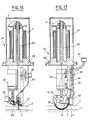
- Figures 13 and 14 show in elevation, in two perpendicular directions and with partial section, a device according to the invention produced in the form of a stitching head.
- FIG. 15 shows, in perspective, a stitching machine incorporating the head of FIGS. 13 and 14.
- FIG. 16 illustrates the formation of a final composite part, by machining a raw part, obtained by impregnation with a curable binder of a reinforcing element produced according to the invention.
- FIG. 1 shows a support 1 on which a substrate 2 of resistant fibers rests, as well as a stitching needle 3.1, intended to introduce a fiber 4 inside said substrate 2.
- the support 1 can be made of any desired material, such as metallic and possibly be covered with a coating (not shown), for example made of polytetrafluoroethylene. However, it can also be made of foam material, as is known in the art. Depending on the shape of the reinforcement element to be obtained, it can be constituted by a simple plate (which is represented in FIG. 1) or else by a mandrel having a shape of revolution and intended to be driven in rotation during the stitching operation (figure 15).
- the resistant fiber substrate 2 can be of the two-dimensional type, consisting of fibers crossed in at least two directions.
- the fiber 4 is intended to form the third dimension of said substrate.
- the substrate 2 can also be of the three-dimensional type and then the fiber 4 is intended to form a reinforcement for the third dimension.
- the substrate 2 can be formed on the support 1 or else be produced and brought to said support to receive the curved stitching operations there.
- the resistant fibers constituting the substrate 2 and the fiber 4 can be of different known types, such as glass, carbon, boron, KEVLAR (registered trademark), etc.
- the needle 3.1 has a circular shape, with a center 5. It is hollow and is traversed by an internal channel 6, emerging through a lateral eye 7, adjacent to the tip 8 of said needle and arranged in the concavity thereof. On the side opposite to the point 8, the internal channel 6 opens out through an orifice 9.
- the internal channel 6 is intended to be crossed by the fiber 4, entering through the orifice 9 and leaving through the lateral eye 7.
- the internal channel 6 comprises a rounded flare 10 at the level of the orifice 9, while an internal rounded bead 11 is provided on the edge of the eye 7, opposite the point 8.
- the end of the needle 3.1, opposite the point 8, is fixed in a needle holder 12, capable of being animated (see the double arrow F) with a back-and-forth movement in rotation around d 'an axis 13-13, passing through the center 5 of the needle 3.1 and at least substantially perpendicular to the plane thereof. Furthermore, a relative movement of movement is generated between the assembly of the support 1 and the substrate 2, on the one hand, and the needle 3.1, on the other hand.
- said needle 3.1 introduces into substrate 2 a curved segment 4b of said fiber 4, segment 4b of a pair of segments 4a, 4b being connected to the segment 4a of the pair of segments 4a, 4b following by a bridge 4c, parallel to the axis 13-13, forming during the relative displacement f1, while, on the side opposite to the bridges 4c, the two segments 4a and 4b d 'the same pair are connected to each other by a 4d loop.
- FIGS. 3a1, 2b1 and 3c1 which correspond to schematic views along the line III-III in FIG. 1 and on which, for clarity purposes, the segments 4a and 4b have been offset in the thickness direction of the substrate 2.
- FIG. 3a1 a stitching configuration has been shown for which the segments 4a and 4b are tangent to the face 1a of the support 1 on which the substrate 2 rests and the loops 4d appear outside the free face 2a of said substrate, through which the needle 3.1 penetrates.
- Such a stitching configuration is advantageous when a support 1 is used in which the needle 3.1 cannot penetrate (metal support for example) and it is desired that the segments 4a and 4b constitute a reinforcement over the entire thickness of said substrate 2.
- the support 1 was made of a material capable of being easily penetrated by the needle 3.1, the segments 4a and 4b could pass through at least the surface layer of said support. This is in particular advantageous when the support 1 is made of a material which, moreover, is destructible after production of the reinforcing element.
- the loops 4d are also external to the substrate 2, on the side of the free face 2a thereof, but the segments 4a and 4b do not penetrate into said substrate up to the face 1a of the support 1.
- the segments 4a and 4b can constitute a surface reinforcement of the substrate 2.
- the loops 4d are formed inside the substrate 2, for example at the level of the free face 1a of the support 1, and are retained by the pressure and the friction exerted by the substrate material 2.
- FIG. 3d1 it is assumed to have carried out a first stitching operation similar to that of FIG. 3c1, then a second similar operation, symmetrical with the first with respect to the plane passing through the axis 13-13 and orthogonal to support 1.
- FIGS. 3a2 to 3d2 corresponds to Figure 3a1 to 3d1, of index a, b, c or d identical.
- the bridges 4c instead of being perpendicular to the plane of the drawings as in FIGS. 3a1 to 3d1 (the pairs of adjacent segments 4a, 4b being thus superimposed), are on the contrary parallel to the plane of FIGS. 3a2 to 3d2 , so that they are visible thereon and that several pairs of consecutive curved segments 4a, 4b are also visible.
- the relative movement of the needle 3.1 relative to the support 1 does not necessarily take place in one of the directions f1 or f2. Such relative displacement could take place in any other direction, for example at 45 ° relative to f1 and f2.
- this relative displacement is not necessarily linear and that it can follow a curved trajectory, such as circular, helical, spiral, etc. or even a combination of such trajectories.
- FIG. 4,5 and 6 there is illustrated a first alternative embodiment 3.2 of the needle 3.1.
- the needle 3.2 is also circular, from the center 5. However, instead of being hollow, it is full and it has a thread guide groove 14 along its convexity. On the side of its point 8, it has an eye 15 facing its concavity and in communication, through a passage 16, with said groove 14. It is easily understood that the needle 3.2 operates in a similar fashion to the needle 3.1, the fiber 4 being guided by the groove 14, as far as the eye 15 (see FIG. 4), instead of being guided by the internal channel 6.
- the second alternative embodiment 3.3 of the needle 3.1 shown in FIG. 7, is circular, of center 5. On the side of its tip 8, it comprises a hook 17 turned towards its concavity and which can be closed by a valve formed by the end of a circular rod 18, which can slide inside a channel 19 provided in said needle, under the action of a translational control device 20.
- the needle 3.3 operates somewhat differently that of needles 3.1 and 3.2.
- the valve of the needle 3.3 being closed, said needle is caused to cross, during its forward movement, the substrate 2 and to come out through the free face thereof.
- the valve opens and the hook 17 grasps the fiber 4, supplied by an auxiliary device 21, after which said valve closes and the needle 3.3 pulls the fiber 4 through said substrate during its withdrawal, simultaneously forming the segments 4a and 4b of a pair of segments, said fiber being gripped by the hook 17 at the level of a loop 4d.
- the needle 3.3 projects said loop 4d, after which a new cycle can start again. In this way, a loop being formed is passed through the previously made loop, so that the 4d loops are linked together by a chain stitch.
- the needle 3.3 requires the crossing of the free face 2a of the substrate 2 at the end of the forward movement of said needle, so that it cannot carry out the stitching configurations illustrated by FIGS. 3c1, 3d1, 3c2 and 3d2.
- valve needle operating in a manner analogous to the needle 3.3.
- the valve 22 is rotary and automatic, opening in the forward movements of the needle under the thrust of the loop 4d which has just been formed, and coming to be partially housed in a housing 23 provided in the concavity of said needle.
- the valve is tilted to the closed position of the hook 17 under the pressure of the material of the substrate 2.
- FIG 9 there is shown in front view, by completing it, the device of Figure 1.
- an arm 30, which is secured to displacement means not shown of a machine for be able to move relative to the support 1 and which carries, at its end facing said support 1, the needle holder 12 mounted articulated around the axis 13-13, by means of a hinge 31.
- a thread clamp 32 is mounted on the needle holder 12, on the side of the orifice 9 of the needle 3.1, opposite the tip 8.
- this wire clamp comprises a fixed part 32a and a movable part 32b, controllable so as to be able to move away from or closer to said part 32a, it that is to say that the fiber 4, which passes between the fixed and mobile parts 32a and 32b, can be free to pass between them or on the contrary be pinched between them.
- FIG. 10 illustrates an operating mode of the device of FIG. 9, mainly used for thin substrates 2.
- the needle 3.1 undergoes, the thread clamp 32 being open, a return rotation around the axis 13-13 of amplitude A sufficient for the length 33 of fiber 4 leaving the needle and between the eye 7 and the substrate 2 corresponds to the sum of the lengths of the bridge 4c, the curved segment 4a and the loop 4d.
- the bridge 4c and the curved segment 4a After having closed the wire clamp 32, it is therefore possible to make the bridge 4c and the curved segment 4a by rotating the needle 3.1 around its axis 13-13, from this return position, in the direction of the substrate 2.
- the thread clamp 32 is opened before the needle begins its withdrawal stroke.
- the curved segment 4b is formed, for example by virtue of the friction exerted by the substrate 2 on the fiber 4.
- this friction is not sufficient, use a member for retaining the loop 4d.
- the arm 30 is moved orthogonally to the support 1.
- the axis 13-13 can be passed from a first position 13.1 brought close to a position 13.2 distant from the support 1, then to a second close position 13.3. So in this movement of alienation and closeness from the axis 13-13 of the substrate 2, associated with the return stroke of the needle 3.1 around said axis 13.13, it is possible to obtain a displacement amplitude B sufficient to release the clamp at the exit of said needle -wire 32 being open, a length 34 of fiber 4 corresponding to the sum of lengths of the bridge 4c, of the segment 4a and of the loop 4d. This length of fiber 34 is stitched into the substrate 2, when the axis 13-13 occupies its close position 13.3.
- FIG. 12a illustrate yet another mode of operation.
- the needle 21 has just been displaced by the pitch p , corresponding to the bridge 4c, and an adequate length 35 of fiber 4 is available at the outlet of the needle 3.1.
- the wire clamp 32 is closed.
- the stitching operation begins by rotating the needle 3.1 ( Figure 12b) and continues until, after insertion of the segment 4a, the loop 4d appears on the face 2a ( Figure 12c).
- a retaining member 36 grips the loop 4d.
- the thread clamp 32 opens and the needle 3.1 performs its return-to-rotation stroke by forming the segment 4b (FIG. 12d). At the end of the return stroke (FIG.
- a member 37 comes to grip the fiber 4 at the outlet of the needle 3.1 to form the length 35.
- the thread clamp 32 closes and the members 36 and 37 are retracted and the device (see FIG. 12f) is ready to move from step p to take the position illustrated in FIG. 12a. Another stitching cycle can begin.
- FIG. 13 and 14 illustrate an embodiment of a stitching head 40 according to the invention.
- the arm 30 supports a reserve 41 of fiber 4 which is brought to the needle 3 through a guide 42.
- the arm 30 also carries a motor 43 for actuating the needle 3 in rotation about the axis 13.13 , a member 44 for actuating the loop retaining member 36 and a member 46 for actuating the fiber gripping member 37.
- the various motors and members 43 to 46 are connected to control devices (not shown) by a connector 47.
- the stitching head 40 has a flange 48 for its attachment to a stitching machine such as that shown in FIG. 15.
- the machine 50 shown in FIG. 15, comprises an arm 51 which can be moved in three dimensions X, Y and Z, relative to a frame 52.
- the arm 51 can be moved vertically in Z, relative to a carriage 53, thanks to a motor 54, while the carriage 53 is mounted mobile in Y on a beam 55 thanks to a motor 56 and that said beam 55 is itself mounted mobile in X, relative to the frame 52, thanks to a motor 57.
- the stitching head 40 is mounted at the lower end of the arm 51 so that it can be rotatable around each of the axes X, Y and Z.
- the support 1, illustrated in FIG. 15 under the shape of a rotary mandrel, carries the substrate 2.
- a control station 58 makes it possible to control the movement of the head 40 relative to the substrate 2 and the various operations of stitching the needle 3 into the substrate.
- the support 1 can have any desired shape and the direction of the stitching lines, both relative to the support 1 and relative to the plane of the needle 3, can be chosen according to the purpose to be obtained.
- the stitching depth in the substrate 2 can be straight, curved, circular, helical, etc.
Landscapes
- Engineering & Computer Science (AREA)
- Textile Engineering (AREA)
- Mechanical Engineering (AREA)
- Chemical & Material Sciences (AREA)
- Composite Materials (AREA)
- Nonwoven Fabrics (AREA)
- Sewing Machines And Sewing (AREA)
- Laminated Bodies (AREA)
- Moulding By Coating Moulds (AREA)
- Chemical Or Physical Treatment Of Fibers (AREA)
- Yarns And Mechanical Finishing Of Yarns Or Ropes (AREA)
- Multicomponent Fibers (AREA)
- Reinforced Plastic Materials (AREA)
- Inorganic Fibers (AREA)
Abstract
Description
La présente invention concerne un procédé et un dispositif pour la réalisation d'éléments d'armature composés de fibres résistantes distribuées selon trois dimensions. Elle concerne également les pièces composites obtenues à partir desdits éléments d'armature, après imprégnation de ceux-ci à l'aide d'un liant durcissable, tel qu'une résine synthétique.The present invention relates to a method and a device for producing reinforcing elements composed of resistant fibers distributed in three dimensions. It also relates to the composite parts obtained from said reinforcing elements, after impregnation thereof with the aid of a curable binder, such as a synthetic resin.
On connaît déjà, par exemple par les brevets américains US-A-2 283 802 et US-A-3 322 868, un procédé pour réaliser des éléments composés de fibres distribuées selon trois dimensions. Dans ces techniques connues, on forme un substrat de telles fibres croisées suivant au moins deux directions, puis on lie entre elles les fibres dudit substrat par piquage, en introduisant une fibre continue dans ledit substrat au moyen d'une aiguille animée d'un mouvement de va-et-vient, tandis que se produit un déplacement relatif de ladite aiguille par rapport audit substrat, de sorte que ladite fibre continue forme une ligne brisée de piquage à l'intérieur dudit substrat.Already known, for example from American patents US-A-2,283,802 and US-A-3,322,868, a process for producing elements composed of fibers distributed in three dimensions. In these known techniques, a substrate of such crossed fibers is formed in at least two directions, then the fibers of said substrate are bonded together by stitching, by introducing a continuous fiber into said substrate by means of a moving needle. back and forth, while there is a relative displacement of said needle relative to said substrate, so that said continuous fiber forms a broken line of stitching inside said substrate.
La mise en oeuvre de telles techniques ne soulève aucune difficulté, lorsque les deux faces du substrat sont dégagées, car alors ladite aiguille peut pénétrer dans ledit substrat par une desdites faces et ressortir par la face opposée. En revanche, lorsque ledit substrat repose sur un support, il est nécessaire d'aménager spécialement ledit support.The implementation of such techniques does not raise any difficulty, when the two faces of the substrate are released, because then said needle can penetrate into said substrate by one of said faces and exit through the opposite face. On the other hand, when said substrate rests on a support, it is necessary to specially arrange said support.
Par exemple, dans le brevet américain US-A-4 080 915 dans lequel ledit support est rigide, on prévoit d'aménager dans celui-ci des ouvertures, afin de permettre à l'extrémité de l'aiguille d'y pénétrer sans se briser. On remarquera qu'une telle solution limite fortement les possibilités de piquage, puisque le nombre d'ouvertures pratiquées dans le support est forcément limité et qu'il est impératif que, à chaque point, ladite aiguille se trouve en regard d'une telle ouverture. Ainsi, dans ce brevet antérieur, on prévoit que les ouvertures sont des fentes allongées et que les lignes de piquage sont rectilignes, en correspondance avec lesdites fentes. On voit donc que, non seulement la densité des points de piquage sur le substrat ne peut être que faible, mais encore que la forme des lignes de piquage et la distribution des points de piquage sont imposées une fois pour toutes par lesdites ouvertures.For example, in American patent US-A-4 080 915 in which said support is rigid, provision is made to make openings in it, in order to allow the end of the needle to penetrate there without to break. It will be noted that such a solution greatly limits the possibilities of stitching, since the number of openings made in the support is necessarily limited and it is imperative that, at at each point, said needle is located opposite such an opening. Thus, in this prior patent, it is provided that the openings are elongated slots and that the stitching lines are rectilinear, in correspondence with said slots. It can therefore be seen that not only can the density of the stitching points on the substrate be only low, but also that the shape of the stitching lines and the distribution of the stitching points are imposed once and for all by said openings.
En revanche, dans le brevet américain US-A-4 863 660, on prévoit de réaliser le support en une matière mousse ou analogue, permettant la pénétration de la pointe de l'aiguille. Dans ce cas, on n'est plus limité en ce qui concerne la densité des points de piquage ou la forme des lignes de piquage, mais il est nécessaire de réaliser le support en une matière aisément destructible, pour pouvoir dégager le substrat dudit support.On the other hand, in American patent US-A-4,863,660, provision is made to produce the support in a foam material or the like, allowing penetration of the tip of the needle. In this case, it is no longer limited as regards the density of the stitching points or the shape of the stitching lines, but it is necessary to produce the support in an easily destructible material, in order to be able to disengage the substrate from said support.
La présente invention a pour objet de remédier à ces inconvénients et de permettre le piquage d'un substrat de fibres reposant sur un support sans limitation de la densité des points de piquage ou de la forme des lignes de piquage et sans aménagement particulier dudit support.The object of the present invention is to remedy these drawbacks and to allow the stitching of a fiber substrate resting on a support without limiting the density of the stitching points or the shape of the stitching lines and without any particular arrangement of said support.
A cette fin, selon l'invention, le procédé pour la réalisation d'éléments d'armature composés de fibres résistantes distribuées selon trois dimensions, procédé dans lequel, dans un substrat reposant sur un support et constitué de telles fibres croisées suivant au moins deux directions, on introduit par piquage, depuis la face libre dudit substrat opposée audit support, une fibre continue au moyen d'une aiguille animée d'un mouvement de va-et-vient, un déplacement relatif étant de plus engendré entre ledit support et ladite aiguille, de sorte que ladite fibre continue est constituée à l'intérieur dudit substrat d'une suite de segments consécutifs formant une ligne brisée de piquage, est remarquable en ce que ladite aiguille est courbe et impose à chaque segment de ladite fibre continue une forme courbe semblable et en ce que le mouvement de va-et-vient de ladite aiguille courbe s'effectue en rotation autour d'un axe perpendiculaire au plan de ladite aiguille et disposé du côté concave de celle-ci. De préférence, ladite aiguille courbe présente une forme circulaire et ledit axe de rotation est coaxial à ladite aiguille.To this end, according to the invention, the method for producing reinforcing elements composed of resistant fibers distributed in three dimensions, method in which, in a substrate resting on a support and consisting of such fibers crossed in at least two directions, a continuous fiber is introduced by stitching, from the free face of said substrate opposite to said support, by means of a needle driven back and forth, a relative displacement being moreover generated between said support and said needle, so that said continuous fiber is formed inside said substrate of a following consecutive segments forming a broken line of stitching, is remarkable in that said needle is curved and imposes on each segment of said continuous fiber a similar curved shape and in that the reciprocating movement of said curved needle s 'rotates about an axis perpendicular to the plane of said needle and disposed on the concave side thereof. Preferably, said curved needle has a circular shape and said axis of rotation is coaxial with said needle.
Ainsi, grâce à l'invention, on peut faire en sorte que, au maximum, ladite aiguille courbe au cours de son mouvement de va-et-vient vienne tangenter la surface dudit support sur laquelle repose ledit substrat. Ladite aiguille courbe n'a donc pas à pénétrer dans ledit support pour réaliser son opération de piquage, de sorte que ledit support n'a pas à être aménagé spécialement à cet effet. Il en résulte donc, de plus, que l'on peut faire suivre à ladite aiguille toute trajectoire désirée, ainsi que de lui faire exécuter toute densité et distribution de points de piquage désirées.Thus, thanks to the invention, it is possible to ensure that, at most, said curved needle during its back-and-forth movement comes to tangent the surface of said support on which said substrate rests. Said curved needle therefore does not have to penetrate into said support to carry out its stitching operation, so that said support does not have to be arranged specially for this purpose. It therefore therefore results, moreover, that said needle can be made to follow any desired trajectory, as well as to make it execute any density and distribution of desired stitching points.
Par exemple, au cours de son mouvement de va-et-vient, ladite aiguille courbe peut venir tangenter la face dudit support sur laquelle repose ledit substrat. Au contraire, ladite aiguille courbe peut rester éloignée de la face dudit support sur laquelle repose ledit substrat.For example, during its back-and-forth movement, said curved needle can come to tangent the face of said support on which said substrate rests. On the contrary, said curved needle can remain distant from the face of said support on which said substrate rests.
De plus, à la fin de la course aller et au début de la course retour de ladite aiguille courbe, la pointe de celle-ci peut faire saillie par rapport à ladite face libre dudit substrat, ou bien cette pointe peut se trouver piquée à l'intérieur dudit substrat.In addition, at the end of the outward stroke and at the start of the return stroke of said curved needle, the point of the latter may protrude relative to said free face of said substrate, or else this point may be pricked at the inside said substrate.
Par ailleurs, le déplacement relatif entre ledit support et ladite aiguille peut être rectiligne ou courbe.Furthermore, the relative movement between said support and said needle can be straight or curved.
Ce déplacement relatif entre ledit support et ladite aiguille peut être parallèle au plan de ladite aiguille. Il peut également être perpendiculaire au plan de ladite aiguille.This relative movement between said support and said needle can be parallel to the plane of said needle. It can also be perpendicular to the plane of said needle.
De plus, le déplacement relatif entre ledit support et ladite aiguille peut être incliné d'un angle différent de 90° par rapport au plan de ladite aiguille.In addition, the relative displacement between said support and said needle can be inclined at an angle different from 90 ° relative to the plane of said needle.
Généralement, le déplacement relatif entre ledit support et ladite aiguille s'effectue de façon que l'axe de rotation de ladite aiguille reste à distance constante dudit support. Toutefois, lors du déplacement relatif entre ledit support et ladite aiguille, l'axe de rotation de ladite aiguille peut s'écarter et se rapprocher dudit support, par exemple pour sortir de ladite aiguille la quantité de fibre nécessaire à la formation d'un point de piquage.Generally, the relative movement between said support and said needle takes place so that the axis of rotation of said needle remains at constant distance from said support. However, during the relative displacement between said support and said needle, the axis of rotation of said needle can deviate and come closer to said support, for example to exit from said needle the amount of fiber necessary for the formation of a point of stitching.
La présente invention concerne également un dispositif pour la mise en oeuvre du procédé.The present invention also relates to a device for implementing the method.
A cet effet le dispositif pour la réalisation d'éléments d'armature composés de fibres résistantes distribuées selon trois dimensions, dispositif comportant :
- . un support sur lequel repose un substrat constitué de telles fibres croisées suivant au moins deux directions ;
- . une aiguille susceptible d'introduire dans ledit substrat, depuis la face libre de celui-ci opposée audit support, une fibre continue ;
- . des moyens pour animer ladite aiguille d'un mouvement de va-et-vient ; et
- . des moyens pour engendrer un déplacement relatif dudit support par rapport à ladite aiguille ; est remarquable en ce que :
- ladite aiguille est courbe et guide ladite fibre continue à l'intérieur dudit substrat ; et
- des moyens sont prévus pour que l'aiguille soit commandée en rotation de va-et-vient autour d'un axe perpendiculaire au plan de ladite aiguille et disposé du côté concave de celle-ci.
- . a support on which rests a substrate made of such fibers crossed in at least two directions;
- . a needle capable of introducing into said substrate, from the free face thereof opposite said support, a continuous fiber;
- . means for moving said needle back and forth; and
- . means for generating a relative displacement of said support relative to said needle; is remarkable in that:
- said needle is curved and guides said continuous fiber inside said substrate; and
- means are provided so that the needle is controlled to rotate back and forth around an axis perpendicular to the plane of said needle and disposed on the concave side thereof.
Ladite aiguille courbe peut comporter, pour le guidage de ladite fibre, un canal interne débouchant, au voisinage de la pointe de ladite aiguille, par un chas latéral. De préférence, ledit chas latéral se trouve dans la concavité de ladite aiguille.Said curved needle may comprise, for guiding said fiber, an internal channel opening, in the vicinity of the point of said needle, by a lateral eye. Preferably, said lateral eye is located in the concavity of said needle.
En variante, ladite aiguille courbe peut comporter un sillon guide-fil le long de sa convexité et un chas latéral dans sa concavité au voisinage de sa pointe, ledit chas étant en communication avec ledit sillon par l'intermédiaire d'un passage.As a variant, said curved needle may include a thread guide groove along its convexity and a lateral eye in its concavity in the vicinity of its tip, said eye being in communication with said groove via a passage.
Ladite aiguille courbe peut également comporter, au voisinage de sa pointe, un crochet tourné vers sa concavité et obturable par un clapet. Ledit clapet peut être commandé par un dispositif ou bien être commandé automatiquement par ladite fibre et par ledit substrat.Said curved needle may also include, in the vicinity of its tip, a hook facing its concavity and closable by a valve. Said valve can be controlled by a device or else be controlled automatically by said fiber and by said substrate.
Avantageusement, ladite aiguille est montée dans un porte-aiguille articulé, autour dudit axe de rotation de l'aiguille, sur un bras déplaçable par rapport audit support. De préférence, un pince-fil commandable est monté sur ledit porte-aiguille et ledit bras porte une réserve de fibre pour ladite aiguille.Advantageously, said needle is mounted in a needle holder articulated, around said axis of rotation of the needle, on an arm movable relative to said support. Preferably, a controllable thread clamp is mounted on said needle holder and said arm carries a reserve of fiber for said needle.
Eventuellement, ledit bras porte de plus un mécanisme pour tirer la fibre à la sortie de ladite aiguille entre chaque point de piquage. Ledit bras peut également porter un mécanisme pour former une boucle lorsque la pointe de ladite aiguille après avoir pénétrer dans ledit substrat, ressort de ladite surface libre de celui-ci.Optionally, said arm further carries a mechanism for pulling the fiber at the outlet of said needle between each stitching point. Said arm may also carry a mechanism for forming a loop when the point of said needle after entering said substrate, emerges from said free surface thereof.
De préférence, ledit bras est solidaire d'une machine susceptible de le déplacer par rapport au support.Preferably, said arm is integral with a machine capable of moving it relative to the support.
Un tel support peut être fixe ; au contraire, il peut être constitué par un mandrin rotatif.Such a support can be fixed; on the contrary, it can be constituted by a rotary mandrel.
Ainsi, grâce à l'invention, on obtient un élément d'armature composé de fibres résistantes distribuées selon trois dimensions, ledit élément d'armature comportant un substrat constitué de telles fibres croisées suivant au moins deux directions, et étant remarquable en ce qu'il comporte des segments de fibre courbes disposés dans l'épaisseur dudit substrat.Thus, thanks to the invention, a reinforcing element is obtained composed of resistant fibers distributed in three dimensions, said reinforcing element comprising a substrate made of such fibers crossed in at least two directions, and being remarkable in that it comprises curved fiber segments arranged in the thickness of said substrate.
A partir de cet élément d'armature, on peut réaliser une pièce composite par imprégnation dudit élément avec un liant durcissable. La pièce ainsi obtenue peut éventuellement être usinée, au moins superficiellement, pour permettre l'obtention d'une pièce définitive.From this reinforcing element, a composite part can be produced by impregnating said element with a curable binder. The part thus obtained can possibly be machined, at least superficially, to allow obtaining a final part.
Les figures du dessin annexé feront bien comprendre comment l'invention peut être réalisée. Sur ces figures, des références identiques désignent des éléments semblables.The figures of the appended drawing will make it clear how the invention can be implemented. In these figures, identical references designate similar elements.
La figure 1 est une vue schématique et partielle en perspective, illustrant le procédé et le dispositif de piquage conformes à l'invention, à l'aide d'une aiguille creuse courbe, traversée par la fibre de piquage.Figure 1 is a schematic and partial perspective view, illustrating the method and the stitching device according to the invention, using a curved hollow needle, crossed by the stitching fiber.
La figure 2 est une coupe, par son plan médian, de l'aiguille creuse de la figure 1.FIG. 2 is a section through its median plane of the hollow needle of FIG. 1.
Les figures 3a1, 3b1, 3c1 et 3d1 sont des schémas illustrant différentes mises en oeuvre du procédé de la présente invention.Figures 3a1, 3b1, 3c1 and 3d1 are diagrams illustrating various implementations of the method of the present invention.
Les figures 3a2, 3b2, 3c2 et 3d2 sont des schémas illustrant d'autres mises en oeuvre du procédé conforme à l'invention.Figures 3a2, 3b2, 3c2 and 3d2 are diagrams illustrating other implementations of the method according to the invention.
La figure 4 montre, en vue semblable à la figure 1, une variante de réalisation de l'aiguille utilisée dans le procédé de l'invention.Figure 4 shows, in a view similar to Figure 1, an alternative embodiment of the needle used in the method of the invention.
La figure 5 est une coupe, par son plan médian, de l'aiguille de la figure 4.FIG. 5 is a section through its median plane of the needle of FIG. 4.
La figure 6 est une coupe transversale de l'aiguille de la figure 4, selon la ligne VI-VI de la figure 5.FIG. 6 is a cross section of the needle of FIG. 4, along the line VI-VI of FIG. 5.
Les figures 7 et 8 montrent, en vues semblables aux figures 1 et 4, d'autres variantes de réalisation de l'aiguille utilisée dans le procédé de l'invention.Figures 7 and 8 show, in views similar to Figures 1 and 4, other alternative embodiments of the needle used in the method of the invention.
La figure 9 montre, en vue de face schématique et partielle, un mode de réalisation du dispositif selon l'invention.Figure 9 shows, in schematic and partial front view, an embodiment of the device according to the invention.
Les figures 10 et 11 illustrent deux modes de mise en oeuvre du procédé conforme à la présente invention.Figures 10 and 11 illustrate two modes of implementation of the method according to the present invention.
Les figures 12a à 12f illustrent plusieurs étapes d'un autre mode de mise en oeuvre du procédé selon l'invention.Figures 12a to 12f illustrate several steps of another embodiment of the method according to the invention.
Les figures 13 et 14 montrent en élévation, selon deux directions perpendiculaires et avec coupe partielle, un dispositif selon l'invention réalisé sous la forme d'une tête de piquage.Figures 13 and 14 show in elevation, in two perpendicular directions and with partial section, a device according to the invention produced in the form of a stitching head.
La figure 15 montre, en perspective, une machine de piquage incorporant la tête des figures 13 et 14.FIG. 15 shows, in perspective, a stitching machine incorporating the head of FIGS. 13 and 14.
La figure 16 illustre la formation d'une pièce composite définitive, par usinage d'une pièce brute, obtenue par imprégnation par un liant durcissable d'un élément d'armature réalisé selon l'invention.FIG. 16 illustrates the formation of a final composite part, by machining a raw part, obtained by impregnation with a curable binder of a reinforcing element produced according to the invention.
Sur la figure 1, on a représenté un support 1 sur lequel repose un substrat 2 de fibres résistantes, ainsi qu'une aiguille de piquage 3.1, destinée à introduire une fibre 4 à l'intérieur dudit substrat 2.FIG. 1 shows a
Le support 1 peut être réalisé en toute matière désirée, telle que métallique et être éventuellement recouvert d'un revêtement (non représenté), par exemple en polytétrafluoroéthylène. Il peut cependant également être réalisé en matière mousse, comme cela est connu dans la technique. En fonction de la forme de l'élément d'armature à obtenir, il peut être constitué par une simple plaque (ce qui est représenté sur la figure 1) ou bien par un mandrin ayant une forme de révolution et destiné à être entraîné en rotation pendant l'opération de piquage (figure 15).The
Le substrat de fibres résistantes 2 peut être du type à deux dimensions, constitué de fibres croisées suivant au moins deux directions. Dans ce cas, la fibre 4 est destinée à former la troisième dimension dudit substrat. Toutefois, le substrat 2 peut également être du type à trois dimensions et alors la fibre 4 est destinée à former un renfort pour la troisième dimension. Le substrat 2 peut être formé sur le support 1 ou bien être réalisé par ailleurs et amené sur ledit support pour y recevoir les opérations de piquage courbe.The
Les fibres résistantes constituant le substrat 2 et la fibre 4 peuvent être de différentes natures connues, telles que verre, carbone, bore, KEVLAR (marque déposée), etc...The resistant fibers constituting the
Comme on peut le voir également sur la figure 2, l'aiguille 3.1 présente une forme circulaire, de centre 5. Elle est creuse et est parcourue par un canal interne 6, débouchant par un chas latéral 7, adjacent à la pointe 8 de ladite aiguille et disposé dans la concavité de celle-ci. Du côté opposé à la pointe 8, le canal interne 6 débouche par un orifice 9. Le canal interne 6 est destiné à être traversé par la fibre 4, entrant par l'orifice 9 et sortant par le chas latéral 7. Afin d'éviter la détérioration, et éventuellement la cassure, de la fibre 4 par frottement contre les parois de l'orifice 9 et du chas latéral 7, le canal interne 6 comporte un évasement arrondi 10 au niveau durit orifice 9, tandis qu'un bourrelet arrondi interne 11 est prévu sur le bord du chas 7, opposé à la pointe 8.As can also be seen in Figure 2, the needle 3.1 has a circular shape, with a
L'extrémité de l'aiguille 3.1, opposée à la pointe 8, est fixée dans un porte-aiguille 12, susceptible d'être animé (voir la double flèche F) d'un mouvement de va-et-vient en rotation autour d'un axe 13-13, passant par le centre 5 de l'aiguille 3.1 et au moins sensiblement perpendiculaire au plan de celle-ci. Par ailleurs, un mouvement de déplacement relatif est engendré entre l'ensemble du support 1 et du substrat 2, d'une part, et l'aiguille 3.1, d'autre part.The end of the needle 3.1, opposite the
Si, comme cela est représenté sur la figure 1, ce mouvement de déplacement relatif s'effectue suivant une direction f1 parallèle à l'axe 13-13, on conçoit aisément (éventuellement à l'aide des informations complémentaires données ci-après) que, à chaque aller de l'aiguille 3.1 (rotation dans le sens des aiguilles d'une montre sur la figure 1), cette aiguille introduit dans le substrat 2 un segment courbe 4a de la fibre 4, et que, à chacun de ses retours (rotation dans le sens inverse des aiguilles d'une montre sur la figure 1), ladite aiguille 3.1 introduit dans le substrat 2 un segment courbe 4b de ladite fibre 4, le segment 4b d'une paire de segments 4a,4b étant relié au segment 4a de la paire de segments 4a,4b suivante par un pont 4c, parallèle à l'axe 13-13, se formant pendant le déplacement relatif f1, tandis que, du côté opposé aux ponts 4c, les deux segments 4a et 4b d'une même paire sont reliés l'un à l'autre par une boucle 4d.If, as shown in FIG. 1, this relative movement of movement takes place in a direction f1 parallel to the axis 13-13, it is easily understood (possibly using the additional information given below) that , each time needle 3.1 goes (clockwise rotation in FIG. 1), this needle introduces into the
Par ailleurs, en fonction du rayon de courbure de l'aiguille 3.1, de la hauteur h de l'axe 13-13 au-dessus du substrat 2 et de l'épaisseur e dudit substrat, de nombreuses configurations de piquage peuvent être obtenues. On en a représenté quelques unes sur les figures 3a1, 2b1 et 3c1, qui correspondent à des vues schématiques selon la ligne III-III de la figure 1 et sur lesquelles, à des fins de clarté, on a représenté les segments 4a et 4b décalés dans le sens de l'épaisseur du substrat 2.Furthermore, depending on the radius of curvature of the needle 3.1, the height h of the axis 13-13 above the
Par exemple, sur la figure 3a1, on a représenté une configuration de piquage pour laquelle les segments 4a et 4b sont tangents à la face la du support 1 sur laquelle repose le substrat 2 et les boucles 4d apparaissent à l'extérieur de la face libre 2a dudit substrat, à travers laquelle pénètre l'aiguille 3.1. Une telle configuration de piquage est avantageuse lorsque l'on utilise un support 1 dans lequel l'aiguille 3.1 ne pourrait pénétrer (support métallique par exemple) et que l'on désire que les segments 4a et 4b constituent un renforcement sur toute l'épaisseur dudit substrat 2.For example, in FIG. 3a1, a stitching configuration has been shown for which the
Il va de soi, toutefois, que si le support 1 était réalisé en une matière susceptible d'être aisément pénétrée par l'aiguille 3.1, les segments 4a et 4b pourraient traverser au moins la couche superficielle dudit support. Ceci est notamment avantageux lorsque le support 1 est réalisé en une matière qui, de plus, est destructible après réalisation de l'élément d'armature.It goes without saying, however, that if the
Dans l'exemple de la figure 3b1, les boucles 4d sont également extérieures au substrat 2, du côté de la face libre 2a de celui-ci, mais les segments 4a et 4b ne pénètrent pas dans ledit substrat jusqu'à la face 1a du support 1. Dans ce cas, les segments 4a et 4b peuvent constituer un renforcement superficiel du substrat 2.In the example of FIG. 3b1, the
En revanche, dans l'exemple de la figure 3c1, les boucles 4d sont formées à l'intérieur du substrat 2, par exemple au niveau de la face libre 1a du support 1, et sont retenues par la pression et le frottement exercés par la matière du substrat 2. Sur la figure 3d1, on a supposé avoir effectué une première opération de piquage analogue à celle de la figure 3c1, puis une seconde opération semblable, symétrique de la première par rapport au plan passant par l'axe 13-13 et orthogonal au support 1.On the other hand, in the example of FIG. 3c1, the
Au lieu de prévoir entre le support 1 et l'aiguille 3.1, comme décrit ci-dessus, un déplacement relatif f1 parallèle à l'axe 13-13, sur les figures 3a2 à 3d2, on a illustré un déplacement rectiligne parallèle à une direction f2 perpendiculaire audit axe 13-13. Ce mode de piquage sera d'ailleurs décrit en détail, à titre d'exemple, en regard des figures 10, 11 et 12a à 12f.Instead of providing between the
Chacune des figures 3a2 à 3d2 correspond la figure 3a1 à 3d1, d'indice a,b,c ou d identique. Dans ce cas, les ponts 4c, au lieu d'être perpendiculaire au plan des dessins comme sur les figures 3a1 à 3d1 (les paires de segments 4a,4b adjacents étant ainsi superposées), sont au contraire parallèles au plan des figures 3a2 à 3d2, de sorte qu'ils sont visibles sur celles-ci et que plusieurs paires de segments courbes 4a,4b consécutives sont également visibles.Each of Figures 3a2 to 3d2 corresponds to Figure 3a1 to 3d1, of index a, b, c or d identical. In this case, the
Bien entendu, le déplacement relatif de l'aiguille 3.1 par rapport au support 1 ne s'effectue pas obligatoirement suivant l'une des directions f1 ou f2. Un tel déplacement relatif pourrait avoir lieu suivant tout autre direction, par exemple à 45° par rapport à f1 et f2. De plus, on comprendra que ce déplacement relatif n'est pas obligatoirement linéaire et qu'il peut suivre une trajectoire courbe, telle que circulaire, hélicoïdale, en spirale, etc... ou bien encore une combinaison de telles trajectoires.Of course, the relative movement of the needle 3.1 relative to the
Sur les figures 4,5 et 6, on a illustré une première variante de réalisation 3.2 de l'aiguille 3.1. L'aiguille 3.2 est également circulaire, du centre 5. Toutefois, au lieu d'être creuse, elle est pleine et elle comporte un sillon guide-fil 14 le long de sa convexité. Du côté de sa pointe 8, elle présente un chas 15 tourné vers sa concavité et en communication, par un passage 16, avec ledit sillon 14. On conçoit aisément que l'aiguille 3.2 fonctionne de façon analogue à l'aiguille 3.1, la fibre 4 étant guidée par le sillon 14, jusqu'à travers le chas 15 (voir la figure 4), au lieu d'être guidée par le canal interne 6.In Figures 4,5 and 6, there is illustrated a first alternative embodiment 3.2 of the needle 3.1. The needle 3.2 is also circular, from the
La seconde variante de réalisation 3.3 de l'aiguille 3.1, montrée par la figure 7, est circulaire, de centre 5. Du côté de sa pointe 8, elle comporte un crochet 17 tourné vers sa concavité et pouvant être fermé par un clapet formé par l'extrémité d'une tige circulaire 18, pouvant coulisser à l'intérieur d'un canal 19 prévu dans ladite aiguille, sous l'action d'un dispositif de commande en translation 20. L'aiguille 3.3 fonctionne de façon quelque peu différente de celle des aiguilles 3.1 et 3.2. Le clapet de l'aiguille 3.3 étant fermé, ladite aiguille est amenée à traverser, lors de son mouvement aller, le substrat 2 et à ressortir à travers la face libre de celui-ci. Le clapet s'ouvre et le crochet 17 saisit la fibre 4, amenée par un dispositif auxiliaire 21, après quoi ledit clapet se referme et l'aiguille 3.3 tire la fibre 4 à travers ledit substrat pendant son retrait, en formant simultanément les segments 4a et 4b d'une paire de segments, ladite fibre étant saisie par le crochet 17 au niveau d'une boucle 4d. En ressortant de la surface 2a, l'aiguille 3.3 fait saillir ladite boucle 4d, après quoi un nouveau cycle peut recommencer. De cette façon, une boucle en cours de formation est passée dans la boucle antérieurement faite, de sorte que les boucles 4d sont liées entre elles par un point de chaînette. On remarquera que l'aiguille 3.3 nécessite la traversée de la face libre 2a du substrat 2 à la fin du mouvement aller de ladite aiguille, de sorte qu'elle ne peut réaliser les configurations de piquage illustrées par les figures 3c1, 3d1, 3c2 et 3d2.The second alternative embodiment 3.3 of the needle 3.1, shown in FIG. 7, is circular, of
Dans la troisième variante de réalisation 3.4 de l'aiguille 3.1, montrée par la figure 8, on retrouve une aiguille à clapet fonctionnant de manière analogue à l'aiguille 3.3. Toutefois, dans ce cas, le clapet 22 est rotatif et automatique, s'ouvrant dans les mouvements aller de l'aiguille sous la poussée de la boucle 4d qui vient d'être formée, et venant se loger partiellement dans un logement 23 prévu dans la concavité de ladite aiguille. Au retour, le clapet est basculé en position fermée du crochet 17 sous la pression de la matière du substrat 2.In the third alternative embodiment 3.4 of the needle 3.1, shown in FIG. 8, there is a valve needle operating in a manner analogous to the needle 3.3. However, in this case, the
Sur la figure 9, on a représenté en vue de face, en le complètant, le dispositif de la figure 1. Sur cette figure 9, on a représenté un bras 30, qui est solidaire de moyens de déplacement non représentés d'une machine pour pouvoir se déplacer par rapport au support 1 et qui porte, à son extrémité dirigée en regard dudit support 1, le porte-aiguille 12 monté articulé autour de l'axe 13-13, par l'intermédiaire d'une articulation 31. De plus, un pince-fil 32 est monté sur le porte-aiguille 12, du côté de l'orifice 9 de l'aiguille 3.1, opposé à la pointe 8. Par exemple, ce pince-fil comporte une partie fixe 32a et une partie mobile 32b, commandable pour pouvoir s'écarter ou se rapprocher de ladite partie 32a, c'est-à-dire que la fibre 4, qui passe entre les parties fixe et mobile 32a et 32b, peut être libre de défiler entre celles-ci ou au contraire être pincée entre elles.In Figure 9, there is shown in front view, by completing it, the device of Figure 1. In this Figure 9, there is shown an
La figure 10 illustre un mode de fonctionnement du dispositif de la figure 9, principalement utilisé pour des substrats 2 de faible épaisseur. Dans ce mode de fonctionnement, à la fin du point précédent, l'aiguille 3.1 subit, le pince-fil 32 étant ouvert, une rotation de retour autour de l'axe 13-13 d'amplitude A suffisante pour que la longueur 33 de fibre 4 sortant de l'aiguille et compris entre le chas 7 et le substrat 2 corresponde à la somme des longueurs du pont 4c, du segment courbe 4a et de la boucle 4d. Après avoir fermé le pince-fil 32, on peut donc réaliser le pont 4c et le segment courbe 4a en faisant tourner l'aiguille 3.1 autour de son axe 13-13, à partir de cette position de retour, en direction du substrat 2. Lorsque l'aiguille 3.1 est arrivée à la fin de sa course de piquage, le pince-fil 32 est ouvert avant que l'aiguille commence sa course de retrait. Ainsi, au cours du retrait de l'aiguille 3.1, se forme le segment courbe 4b, par exemple grâce à la friction qu'exerce le substrat 2 sur la fibre 4. Comme on le verra ci-après, il serait possible bien entendu, dans le cas où cette friction ne serait pas suffisante, d'utiliser un organe de retenue de la boucle 4d.FIG. 10 illustrates an operating mode of the device of FIG. 9, mainly used for
Dans la variante de mode de fonctionnement illustrée par la figure 11, le bras 30 est déplacé orthogonalement au support 1. L'axe 13-13 peut être passé d'une première position 13.1 rapprochée à une position 13.2 éloignée du support 1, puis à une seconde position rapprochée 13.3. Ainsi, dans ce mouvement d'éloignement et de rapprochement de l'axe 13-13 du substrat 2, associé à la course de retour de l'aiguille 3.1 autour dudit axe 13.13, il est possible d'obtenir une amplitude de déplacement B suffisante pour dégager à la sortie de ladite aiguille, le pince-fil 32 étant ouvert, une longueur 34 de fibre 4 correspondant à la somme de longueurs du pont 4c, du segment 4a et de la boucle 4d. Cette longueur de fibre 34 est piquée dans le substrat 2, lorsque l'axe 13-13 occupe sa position rapprochée 13.3.In the variant operating mode illustrated in FIG. 11, the
Les figures 12a à 12f illustrent encore un autre mode de fonctionnement. Sur la figure 12a, l'aiguille 21 vient d'être déplacée du pas p, correspondant au pont 4c, et une longueur adéquate 35 de fibre 4 est disponible à la sortie de l'aiguille 3.1. De plus, le pince-fil 32 est fermé. L'opération de piquage commence en faisant tourner l'aiguille 3.1 (figure 12b) et se poursuit jusqu'à ce que, après insertion du segment 4a, la boucle 4d apparaisse sur la face 2a (figure 12c). Un organe de retenue 36 vient saisir la boucle 4d. Le pince-fil 32 s'ouvre et l'aiguille 3.1 effectue sa course de retour en rotation en formant le segment 4b (figure 12d). A la fin de la course de retour (figure 12e), un organe 37 vient saisir la fibre 4 à la sortie de l'aiguille 3.1 pour former la longueur 35. Le pince-fil 32 se referme et les organes 36 et 37 sont rétractés et le dispositif (voir la figure 12f) est prêt à se déplacer du pas p pour prendre la position illustrée par la figure 12a. Un autre cycle de piquage peut commencer.Figures 12a to 12f illustrate yet another mode of operation. In FIG. 12a, the
Les figures 13 et 14 illustrent un mode de réalisation d'une tête de piquage 40 conforme à l'invention. Le bras 30 supporte une réserve 41 de fibre 4 qui est amenée à l'aiguille 3 à travers un guide 42. Le bras 30 porte de plus un moteur 43 pour l'actionnement de l'aiguille 3 en rotation autour de l'axe 13.13, un organe 44 pour l'actionnement de l'organe de retenue de boucle 36 et un organe 46 pour l'actionnement de l'organe de saisie de fibre 37. Les différents moteur et organes 43 à 46 sont reliés à des dispositifs de commande (non représentés) par un connecteur 47. De plus, la tête de piquage 40 comporte une collerette 48 pour sa fixation sur une machine de piquage telle que celle représentée sur la figure 15.Figures 13 and 14 illustrate an embodiment of a
La machine 50, montrée par la figure 15, comporte un bras 51 pouvant être déplacé suivant trois dimensions X,Y et Z, par rapport à un bâti 52. A cet effet, le bras 51 peut être déplacé verticalement en Z, par rapport à un chariot 53, grâce à un moteur 54, tandis que le chariot 53 est monté mobile en Y sur une poutre 55 grâce à un moteur 56 et que ladite poutre 55 est elle-même montée mobile en X, par rapport au bâti 52, grâce à un moteur 57. La tête de piquage 40 est montée à l'extrémité inférieure du bras 51 pour pouvoir être mobile en rotation autour de chacun des axes X,Y et Z. Par ailleurs, le support 1, illustré sur la figure 15 sous la forme d'un mandrin rotatif, porte le substrat 2. Un poste de commande 58 permet de commander le déplacement de la tête 40 par rapport au substrat 2 et les différentes opérations de piquage de l'aiguille 3 dans le substrat.The
On voit ainsi que, grâce à l'invention, on peut obtenir des éléments d'armature comportant des segments fibreux courbes. Bien entendu, le support 1 peut avoir toute forme désirée et la direction des lignes de piquage, aussi bien par rapport au support 1 que par rapport au plan de l'aiguille 3, peut être choisie selon le but à obtenir. Il en est de même de la profondeur de piquage dans le substrat 2. Par ailleurs, les lignes de piquage peuvent être rectilignes, courbes, circulaires, hélicoïdales, etc...It can thus be seen that, thanks to the invention, it is possible to obtain reinforcing elements comprising curved fibrous segments. Of course, the
Après obtention d'un tel élément d'armature, celui-ci est imprégné, de façon connue, de liant durcissable pour obtenir une pièce 60 (voir la figure 16). Eventuellement, cette pièce 60 est ensuite usinée, au moins superficiellement, pour l'obtention de la pièce définitive 61.After obtaining such a reinforcing element, it is impregnated, in a known manner, with curable binder to obtain a part 60 (see FIG. 16). Optionally, this
Claims (32)
- Process for the production of reinforcement elements composed of strong fibres distributed in three dimensions, according to which process, in a substrate (2) resting on a support (1) and consisting of such fibres intersecting along at least two directions, a continuous fibre (4) is inserted by stitching, from that free face (2a) of the said substrate opposite the said support, by means of a needle (3.1 to 3.4) driven in a to-and-fro motion, a relative movement being additionally generated between the said support and the said needle, so that the said continuous fibre consists, inside the said substrate, of a series of consecutive segments (4a, 4b) forming a broken line, characterized in that:- the said needle (3.1 to 3.4) is curved and forces on each segment (4a, 4b) of the said continuous fibre (4) a similar curved shape; and- the to-and-fro motion of the said curved needle is performed in rotation about an axis (13-13) perpendicular to the plane of the said needle and located on the concave side of the latter.
- Process according to Claim 1, characterized in that the said curved needle (3.1 to 3.4) has a circular shape and in that the said rotation axis (13-13) is coaxial with the said needle.
- Process according to one of Claims 1 and 2, characterized in that, in the course of its to-and-fro motion, the said curved needle (3.1, 3.2, 3.3, 3.4) arrives tangentially at the face (1a) of the said support (1) on which the said substrate (2) rests.
- Process according to one of Claims 1 and 2, characterized in that, in the course of its to-and-fro motion, the said curved needle (3.1, 3.2, 3.3, 3.4) remains remote from that face (1a) of the said support (1) on which the said substrate (2) rests.
- Process according to one of Claims 1 to 4, characterized in that, at the end of the forward stroke and at the beginning of the return stroke of the said curved needle (3.1, 3.2, 3.3, 3.4), the tip (8) of the latter projects with respect to the said free face (2a) of the said substrate.
- Process according to any one of Claims 1 to 4, characterized in that, at the end of the forward stroke and at the beginning of the return stroke of the said needle (3.1, 3.2), the tip (8) of the latter is stitched into the said substrate (2).
- Process according to any one of Claims 1 to 6, characterized in that the relative movement between the said support (1) and the said needle is rectilinear.
- Process according to any one of Claims 1 to 6, characterized in that the relative movement between the said support (1) and the said needle is curved.
- Process according to either one of Claims 7 or 8, characterized in that the relative movement between the said support (1) and the said needle is parallel to the plane of the said needle.
- Process according to either one of Claims 7 or 8, characterized in that the relative movement between the said support and the said needle is perpendicular to the plane of the said needle.
- Process according to either one of Claims 7 or 8, characterized in that the relative movement between the said support and the said needle is inclined at an angle different from 90° with respect to the plane of the said needle.
- Process according to any one of Claims 1 to 11, characterized in that the relative movement between the said support and the said needle is performed so that the rotation axis (13-13) of the said needle remains at a constant distance from the said support (1).
- Process according to any one of Claims 1 to 11, characterized in that, during the relative movement between the said support and the said needle, the rotation axis (13-13) of the said needle may move further away from and nearer to the said support.
- Device for the production of reinforcement elements composed of strong fibres distributed in three dimensions, this device including:· a support (1) on which rests a substrate (2) consisting of such fibres intersecting along at least two directions;· a needle (3.1 to 3.4) capable of inserting a continuous fibre (4) into the said substrate from that free face (2a) of the latter opposite the said support;· means for driving the said needle in a to-and-fro motion; and· means for generating a relative movement of the said support with respect to the said needle; characterized in that:- the said needle (3.1 to 3.4) is curved and guides the said continuous fibre (4) inside the said substrate (2); and- means (12, 43) are provided so that the needle is driven in to-and-fro rotation about an axis (13-13) perpendicular to the plane of the said needle and located on the concave side of the latter.
- Device according to Claim 14, characterized in that the said curved needle has a circular shape and in that the said rotation axis (13-13) is coaxial with the said needle.
- Device according to one of Claims 14 and 15, characterized in that the said curved needle (3.1) includes, for guiding the said fibre, an internal channel (6) emerging, in the vicinity of the tip (8) of the said needle, via a lateral needle eye (7).
- Device according to Claim 16, characterized in that the said lateral needle eye (7) lies in the concavity of the said needle (3.1).
- Device according to one of Claims 14 and 15, characterized in that the said curved needle (3.2) includes a thread-guiding groove (14) along its convexity and a lateral needle eye (15) in its concavity in the vicinity of its tip (8), the said needle eye (15) being in communication with the said groove (14) via a passage (16).
- Device according to one of Claims 14 and 15, characterized in that the said curved needle (3.3, 3.4) includes, in the vicinity of its tip (8), a hook (17) which faces its concavity and can be closed off by a latch (18, 22).
- Device according to Claim 19, characterized in that the said latch is controlled by a device (20).
- Device according to Claim 19, characterized in that the said latch is controlled automatically by the said fibre and by the said substrate.
- Device according to any one of Claims 14 to 21, characterized in that the said needle (3.1 to 3.4) is mounted in a needle holder (12) which pivots, about the said rotation axis (13-13) of the needle, on an arm (30) which can move with respect to the said support (1).
- Device according to Claim 22, characterized in that a controllable thread gripper is mounted on the said needle holder (12).
- Device according to one of Claims 22 and 23, characterized in that the said arm (30) carries a reserve of fibre (41) for the said needle.
- Device according to one of Claims 22 to 24, characterized in that the said arm (30) carries a mechanism (37, 46) for pulling the fibre (4) at the exit of the said needle (3.1 to 3.4) between each stitch.
- Device according to one of Claims 22 to 25, characterized in that the said arm (30) carries a mechanism (36, 45) for forming a loop (4d) when the tip (8) of the said needle, after having penetrated into the said substrate (2), emerges from the said free surface (2a) of the latter.
- Device according to one of Claims 22 to 26, characterized in that the said arm (30) is fastened to a machine (50) capable of moving it with respect to the support (1).
- Device according to any one of Claims 14 to 27, characterized in that the said support (1) is fixed.
- Device according to any one of Claims 14 to 27, characterized in that the said support (1) is a rotary mandrel.
- Reinforcement element composed of strong fibres distributed in three dimensions, the said reinforcement element including a substrate (2) consisting of such fibres intersecting along at least two directions, characterized in that it includes curved fibre segments (4a, 4b) arranged in the thickness of the said substrate (2), these curved fibre segments forming part of the same continuous fibre.
- Composite component including a reinforcement element composed of strong fibres distributed in three dimensions and impregnated with a cured [sic] binder, the said reinforcement element including a substrate (2) consisting of such fibres intersecting along at least two directions, characterized in that curved fibre segments (4a, 4b) are arranged in the thickness of the said substrate (2), these curved fibre segments forming part of the same continuous fibre.
- Composite component according to Claim 31, characterized in that it is machined, at least on the surface.
Applications Claiming Priority (2)
| Application Number | Priority Date | Filing Date | Title |
|---|---|---|---|
| FR9002352A FR2658841B1 (en) | 1990-02-26 | 1990-02-26 | METHOD AND DEVICE FOR PRODUCING REINFORCING ELEMENTS COMPOSED OF RESISTANT FIBERS. |
| FR9002352 | 1990-02-26 |
Publications (2)
| Publication Number | Publication Date |
|---|---|
| EP0444971A1 EP0444971A1 (en) | 1991-09-04 |
| EP0444971B1 true EP0444971B1 (en) | 1995-01-04 |
Family
ID=9394127
Family Applications (1)
| Application Number | Title | Priority Date | Filing Date |
|---|---|---|---|
| EP91400129A Expired - Lifetime EP0444971B1 (en) | 1990-02-26 | 1991-01-21 | Process and device for the production of composite material of resistant fibres |
Country Status (10)
| Country | Link |
|---|---|
| US (2) | US5095833A (en) |
| EP (1) | EP0444971B1 (en) |
| JP (1) | JP2891788B2 (en) |
| AT (1) | ATE116699T1 (en) |
| CA (1) | CA2036985A1 (en) |
| DE (1) | DE69106404T2 (en) |
| ES (1) | ES2069228T3 (en) |
| FR (1) | FR2658841B1 (en) |
| IE (1) | IE61078B1 (en) |
| NO (1) | NO176930C (en) |
Cited By (1)
| Publication number | Priority date | Publication date | Assignee | Title |
|---|---|---|---|---|
| RU208322U1 (en) * | 2021-07-08 | 2021-12-14 | федеральное государственное бюджетное образовательное учреждение высшего образования «Белгородский государственный технологический университет им. В.Г. Шухова» | SEWING MACHINE |
Families Citing this family (38)
| Publication number | Priority date | Publication date | Assignee | Title |
|---|---|---|---|---|
| FR2687174B1 (en) * | 1992-02-11 | 1995-09-22 | Aerospatiale | PROCESS FOR THE PRODUCTION OF A FIBER REINFORCEMENT FOR A COMPOSITE MATERIAL WITH NON-COPLANAR WALLS, AND A COMPOSITE PART COMPRISING SUCH A REINFORCEMENT. |
| FR2687173B1 (en) * | 1992-02-11 | 1995-09-08 | Aerospatiale | PROCESS FOR THE PRODUCTION OF A FIBER REINFORCEMENT FOR A COMPOSITE MATERIAL, AND A COMPOSITE PIECE COMPRISING SUCH A REINFORCEMENT. |
| JPH0675624B2 (en) * | 1992-05-22 | 1994-09-28 | 菅原ミシン株式会社 | Needle movement mechanism of the sewing machine for scooping |
| IL105788A (en) * | 1992-06-01 | 1996-10-16 | Allied Signal Inc | Stitched composite constructions having improved penetration resistance |
| GB9406537D0 (en) * | 1994-03-31 | 1994-05-25 | British Aerospace | Blind stitching apparatus and composite material manufacturing methods |
| US6001968A (en) | 1994-08-17 | 1999-12-14 | The Rockefeller University | OB polypeptides, modified forms and compositions |
| DE19629044C2 (en) * | 1995-07-19 | 1998-12-03 | Deutsch Zentr Luft & Raumfahrt | Flat structure made of fiber composite materials and process for their production |
| DE19813887A1 (en) * | 1998-03-28 | 1999-09-30 | Freundes Und Foerderkreis Des | Method and device for producing sewing seams |
| FR2779749B1 (en) * | 1998-06-10 | 2000-08-11 | Aerospatiale | FIBROUS REINFORCEMENT FOR A PART OF COMPOSITE MATERIAL, AS WELL AS METHOD AND DEVICE FOR ITS IMPLEMENTATION |
| US6196145B1 (en) * | 1998-11-17 | 2001-03-06 | Albany International Techniweave, Inc. | Yarn insertion mechanism |
| DE10040807B4 (en) * | 2000-08-21 | 2004-07-15 | Ksl Keilmann Sondermaschinenbau Gmbh | Blind stitch sewing machine |
| US6467149B2 (en) * | 2000-12-07 | 2002-10-22 | The Goodyear Tire & Rubber Company | Apparatus for injecting materials into a composite |
| US6645333B2 (en) | 2001-04-06 | 2003-11-11 | Ebert Composites Corporation | Method of inserting z-axis reinforcing fibers into a composite laminate |
| US7731046B2 (en) * | 2001-04-06 | 2010-06-08 | Ebert Composites Corporation | Composite sandwich panel and method of making same |
| US6676785B2 (en) | 2001-04-06 | 2004-01-13 | Ebert Composites Corporation | Method of clinching the top and bottom ends of Z-axis fibers into the respective top and bottom surfaces of a composite laminate |
| US7785693B2 (en) | 2001-04-06 | 2010-08-31 | Ebert Composites Corporation | Composite laminate structure |
| US7105071B2 (en) | 2001-04-06 | 2006-09-12 | Ebert Composites Corporation | Method of inserting z-axis reinforcing fibers into a composite laminate |
| US20050025948A1 (en) * | 2001-04-06 | 2005-02-03 | Johnson David W. | Composite laminate reinforced with curvilinear 3-D fiber and method of making the same |
| US7056576B2 (en) * | 2001-04-06 | 2006-06-06 | Ebert Composites, Inc. | 3D fiber elements with high moment of inertia characteristics in composite sandwich laminates |
| US20050118448A1 (en) * | 2002-12-05 | 2005-06-02 | Olin Corporation, A Corporation Of The Commonwealth Of Virginia | Laser ablation resistant copper foil |
| DE102005034393B4 (en) | 2005-07-22 | 2009-04-02 | Airbus Deutschland Gmbh | Process for the production of single or multilayer fiber preforms in the TFP process |
| DE102005034400B4 (en) * | 2005-07-22 | 2010-09-23 | Airbus Deutschland Gmbh | Apparatus for producing a fiber preform having a virtually random surface geometry in the TFP process |
| US7854208B1 (en) * | 2007-05-14 | 2010-12-21 | Martelli John D | Unibody support apparatus and method |
| FR2941710B1 (en) * | 2009-02-05 | 2011-03-18 | Airbus France | PROCESS FOR THE SEWING ASSEMBLY OF FIBROUS ELEMENTS AND DEVICE FOR CARRYING OUT SAID METHOD |
| JP5295899B2 (en) * | 2009-07-29 | 2013-09-18 | 日機装株式会社 | Manufacturing method of fiber reinforced resin composite material |
| DE102010050740B4 (en) * | 2010-11-08 | 2012-12-06 | Airbus Operations Gmbh | Method and device for producing an aircraft structural component |
| US20130315747A1 (en) * | 2012-05-23 | 2013-11-28 | Karsten Schibsbye | Wind turbine blade with improved geometry for reinforcing fibers |
| DE102015110855B4 (en) * | 2015-07-06 | 2019-12-05 | Technische Universität Chemnitz | Method for manufacturing complex 3D preforms |
| FR3062810A1 (en) * | 2017-02-13 | 2018-08-17 | Airbus Operations | METHOD AND SYSTEM FOR ZIGZAG STITCH FASTENING OF A FUNCTIONAL FLEXIBLE ELEMENT ON A FLEXIBLE SUPPORT. |
| US10624738B2 (en) | 2017-02-23 | 2020-04-21 | Edwards Lifesciences Corporation | Heart valve manufacturing devices and methods |
| IL275709B2 (en) * | 2018-01-12 | 2025-06-01 | Edwards Lifesciences Corp | Automatic heart valve suturing |
| CN112702977B (en) | 2018-08-22 | 2024-03-15 | 爱德华兹生命科学公司 | Automatic heart valve manufacturing apparatus and method |
| DE102020202270A1 (en) * | 2020-02-21 | 2021-08-26 | Pfaff Industriesysteme Und Maschinen Gmbh | sewing machine |
| JP2023534384A (en) | 2020-06-09 | 2023-08-09 | エドワーズ ライフサイエンシーズ コーポレイション | Automatic sewing and thread management |
| RU2763580C1 (en) * | 2021-07-08 | 2021-12-30 | федеральное государственное бюджетное образовательное учреждение высшего образования «Белгородский государственный технологический университет им. В.Г. Шухова» | Machine for sewing fabrics |
| US12297573B2 (en) | 2023-05-12 | 2025-05-13 | Rohr, Inc. | Systems and methods for through thickness reinforcement using roll-to-roll veil cloth |
| US12428764B2 (en) * | 2023-05-12 | 2025-09-30 | Rohr, Inc. | Systems and methods for non-linear through thickness reinforcement |
| CN118372487A (en) * | 2024-05-27 | 2024-07-23 | 浙江航引新材料科技有限公司 | Automatic sewing device for reinforcing rib composite material |
Family Cites Families (12)
| Publication number | Priority date | Publication date | Assignee | Title |
|---|---|---|---|---|
| DE411024C (en) * | 1925-03-23 | Masch Werke Zu Frankfurt A M V | Curved sewing needle with a hook-shaped eye for sewing shoes | |
| DE288794C (en) * | ||||
| FR478025A (en) * | 1913-10-03 | 1915-11-19 | Mark Thomas Denne | Curved needle and awl sewing machine |
| US1909434A (en) * | 1930-02-21 | 1933-05-16 | United Mattress Machinery Comp | Side stitching a mattress |
| US3322868A (en) * | 1963-07-02 | 1967-05-30 | Douglas Aircraft Co Inc | Three dimensional reinforced structure |
| US3340586A (en) * | 1965-08-30 | 1967-09-12 | Singer Co | Methods and apparatus for needling textile fibers |
| FR1490415A (en) * | 1965-08-30 | 1967-07-28 | Singer Co | Method and apparatus for needlepointing textile fibers |
| US3950587A (en) * | 1971-01-12 | 1976-04-13 | Breveteam, S.A. | Non-woven textile fiber products having a relief-like structure |
| GB1328972A (en) * | 1971-04-19 | 1973-09-05 | Ethicon Inc | Needled suture |
| FR2315562A1 (en) * | 1975-06-26 | 1977-01-21 | Commissariat Energie Atomique | METHOD AND DEVICES FOR MANUFACTURING BODIES OR PARTS FROM THREE-DIMENSIONAL FABRICS |
| US4506611A (en) * | 1979-10-22 | 1985-03-26 | Hitco | Three-dimensional thick fabrics and methods and apparatus for making same |
| FR2612950B1 (en) * | 1987-03-25 | 1989-06-09 | Aerospatiale | METHOD FOR MANUFACTURING THREE-DIMENSION WOVEN COMPOSITE REINFORCING ELEMENTS, MACHINE FOR IMPLEMENTING SAME AND PRODUCT OBTAINED |
-
1990
- 1990-02-26 FR FR9002352A patent/FR2658841B1/en not_active Expired - Fee Related
-
1991
- 1991-01-21 DE DE69106404T patent/DE69106404T2/en not_active Expired - Fee Related
- 1991-01-21 AT AT91400129T patent/ATE116699T1/en not_active IP Right Cessation
- 1991-01-21 EP EP91400129A patent/EP0444971B1/en not_active Expired - Lifetime
- 1991-01-21 ES ES91400129T patent/ES2069228T3/en not_active Expired - Lifetime
- 1991-01-25 US US07/646,094 patent/US5095833A/en not_active Expired - Fee Related
- 1991-01-29 IE IE30691A patent/IE61078B1/en not_active IP Right Cessation
- 1991-02-25 NO NO910737A patent/NO176930C/en unknown
- 1991-02-25 CA CA002036985A patent/CA2036985A1/en not_active Withdrawn
- 1991-02-26 JP JP3053120A patent/JP2891788B2/en not_active Expired - Lifetime
-
1993
- 1993-04-14 US US08/048,080 patent/US5350615A/en not_active Expired - Fee Related
Cited By (1)
| Publication number | Priority date | Publication date | Assignee | Title |
|---|---|---|---|---|
| RU208322U1 (en) * | 2021-07-08 | 2021-12-14 | федеральное государственное бюджетное образовательное учреждение высшего образования «Белгородский государственный технологический университет им. В.Г. Шухова» | SEWING MACHINE |
Also Published As
| Publication number | Publication date |
|---|---|
| NO910737L (en) | 1991-08-27 |
| NO176930B (en) | 1995-03-13 |
| JPH0610257A (en) | 1994-01-18 |
| NO176930C (en) | 1995-06-21 |
| ES2069228T3 (en) | 1995-05-01 |
| NO910737D0 (en) | 1991-02-25 |
| FR2658841B1 (en) | 1993-06-11 |
| DE69106404D1 (en) | 1995-02-16 |
| CA2036985A1 (en) | 1991-08-27 |
| IE910306A1 (en) | 1991-08-28 |
| IE61078B1 (en) | 1994-09-21 |
| DE69106404T2 (en) | 1995-05-04 |
| EP0444971A1 (en) | 1991-09-04 |
| US5095833A (en) | 1992-03-17 |
| FR2658841A1 (en) | 1991-08-30 |
| ATE116699T1 (en) | 1995-01-15 |
| JP2891788B2 (en) | 1999-05-17 |
| US5350615A (en) | 1994-09-27 |
Similar Documents
| Publication | Publication Date | Title |
|---|---|---|
| EP0444971B1 (en) | Process and device for the production of composite material of resistant fibres | |
| EP0556088B1 (en) | Method of fabricating a fibre reinforcement for a composite structure and structural composite with the same reinforcement | |
| CA1319081C (en) | Machine for implementing a manufacturing process of weaved three-dimensional composite structural members, and product thereof | |
| CA1044882A (en) | Process and devices for the manufacture of three dimensional textile materials_________________________________________________________________ | |
| CA2147040C (en) | Method and apparatus for obtained an armature for a composite material workpiece | |
| FR2687389A1 (en) | DEVICE AND METHOD FOR REALIZING A COMPLEX STRUCTURE PART BY REMOVING CONTACT WITH WIRE OR RIBBON. | |
| EP0833972B1 (en) | Methods and apparatus for making ring-shaped parts out of a composite material, as well as preforms therefor | |
| EP0678611A1 (en) | Needle head and machine for producing a plate-shaped armature for a piece of composite material | |
| EP0678610A1 (en) | Process and machine for the production of an armature plate for a piece of composite material | |
| EP0553000A1 (en) | Process for securing a fibrous structure | |
| FR2941710A1 (en) | Assembling fibrous elements by sewing using yarn, curved needle hook and guide wire, comprises penetrating needle hook in fibrous elements in inlet point and exiting at outlet point, and placing yarn through guide wire into hollow unit | |
| EP0536029B1 (en) | Process and machine for the formation of fibrous armatures | |
| EP0965440A1 (en) | Fibrous reinforcement for composite article as well as method and apparatus for its manufacture | |
| CA2125010A1 (en) | Mechanical linkage device using wound fiber reinforced resin and fabrication process thereof | |
| EP0387129B1 (en) | Needle for performing operations with yarns, slivers and flexible strands, and device for the use of such a needle | |
| EP0046119B1 (en) | Needle with an eye that can be opened | |
| EP4015686B1 (en) | Mechanism for forming a shed and jacquard loom equipped with such a mechanism | |
| FR2941711A1 (en) | Curved needle hook for assembling fibrous elements by sewing using a yarn, comprises a hollow tube with a cutout forming a hollow unit at its near free end, and a sharp tip fixed to the end of the hollow tube | |
| CA2411710A1 (en) | Process for making a multidirectional textile preform, device therefor and resulting preform | |
| BE1003829A6 (en) | Method and device for making a carpet knotted. | |
| FR2660673A1 (en) | Process for producing preforms by means of a woven and wound texture for the manufacture of pieces of composite material | |
| CA1323287C (en) | Tridimensional woven composite reinforcement member | |
| FR3098444A1 (en) | A method of reinforcing a panel and a method of manufacturing a composite panel implementing such a method | |
| CH339594A (en) | Process for making a selvedge using a shuttle-less loom, and loom for implementing this process | |
| FR2500820A1 (en) | Textile winding machine - has side plate bobbin support with projecting hook |
Legal Events
| Date | Code | Title | Description |
|---|---|---|---|
| PUAI | Public reference made under article 153(3) epc to a published international application that has entered the european phase |
Free format text: ORIGINAL CODE: 0009012 |
|
| AK | Designated contracting states |
Kind code of ref document: A1 Designated state(s): AT BE CH DE DK ES GB IT LI NL SE |
|
| 17P | Request for examination filed |
Effective date: 19911029 |
|
| 17Q | First examination report despatched |
Effective date: 19930903 |
|
| GRAA | (expected) grant |
Free format text: ORIGINAL CODE: 0009210 |
|
| AK | Designated contracting states |
Kind code of ref document: B1 Designated state(s): AT BE CH DE DK ES GB IT LI NL SE |
|
| PG25 | Lapsed in a contracting state [announced via postgrant information from national office to epo] |
Ref country code: NL Effective date: 19950104 Ref country code: DK Effective date: 19950104 Ref country code: AT Effective date: 19950104 |
|
| REF | Corresponds to: |
Ref document number: 116699 Country of ref document: AT Date of ref document: 19950115 Kind code of ref document: T |
|
| PG25 | Lapsed in a contracting state [announced via postgrant information from national office to epo] |
Ref country code: LI Effective date: 19950131 Ref country code: CH Effective date: 19950131 |
|
| REF | Corresponds to: |
Ref document number: 69106404 Country of ref document: DE Date of ref document: 19950216 |
|
| GBT | Gb: translation of ep patent filed (gb section 77(6)(a)/1977) |
Effective date: 19950119 |
|
| ITF | It: translation for a ep patent filed | ||
| PG25 | Lapsed in a contracting state [announced via postgrant information from national office to epo] |
Ref country code: SE Effective date: 19950404 |
|
| REG | Reference to a national code |
Ref country code: ES Ref legal event code: FG2A Ref document number: 2069228 Country of ref document: ES Kind code of ref document: T3 |
|
| NLV1 | Nl: lapsed or annulled due to failure to fulfill the requirements of art. 29p and 29m of the patents act | ||
| REG | Reference to a national code |
Ref country code: CH Ref legal event code: PL |
|
| PLBE | No opposition filed within time limit |
Free format text: ORIGINAL CODE: 0009261 |
|
| STAA | Information on the status of an ep patent application or granted ep patent |
Free format text: STATUS: NO OPPOSITION FILED WITHIN TIME LIMIT |
|
| 26N | No opposition filed | ||
| PGFP | Annual fee paid to national office [announced via postgrant information from national office to epo] |
Ref country code: ES Payment date: 19990119 Year of fee payment: 9 |
|
| PGFP | Annual fee paid to national office [announced via postgrant information from national office to epo] |
Ref country code: GB Payment date: 19990121 Year of fee payment: 9 Ref country code: DE Payment date: 19990121 Year of fee payment: 9 |
|
| PGFP | Annual fee paid to national office [announced via postgrant information from national office to epo] |
Ref country code: BE Payment date: 19990201 Year of fee payment: 9 |
|
| PG25 | Lapsed in a contracting state [announced via postgrant information from national office to epo] |
Ref country code: GB Free format text: LAPSE BECAUSE OF NON-PAYMENT OF DUE FEES Effective date: 20000121 |
|
| PG25 | Lapsed in a contracting state [announced via postgrant information from national office to epo] |
Ref country code: ES Free format text: LAPSE BECAUSE OF NON-PAYMENT OF DUE FEES Effective date: 20000122 |
|
| PG25 | Lapsed in a contracting state [announced via postgrant information from national office to epo] |
Ref country code: BE Free format text: LAPSE BECAUSE OF NON-PAYMENT OF DUE FEES Effective date: 20000131 |
|
| BERE | Be: lapsed |
Owner name: AEROSPATIALE SOC. NATIONALE INDUSTRIELLE Effective date: 20000131 |
|
| GBPC | Gb: european patent ceased through non-payment of renewal fee |
Effective date: 20000121 |
|
| PG25 | Lapsed in a contracting state [announced via postgrant information from national office to epo] |
Ref country code: DE Free format text: LAPSE BECAUSE OF NON-PAYMENT OF DUE FEES Effective date: 20001101 |
|
| REG | Reference to a national code |
Ref country code: ES Ref legal event code: FD2A Effective date: 20011010 |
|
| PG25 | Lapsed in a contracting state [announced via postgrant information from national office to epo] |
Ref country code: IT Free format text: LAPSE BECAUSE OF NON-PAYMENT OF DUE FEES;WARNING: LAPSES OF ITALIAN PATENTS WITH EFFECTIVE DATE BEFORE 2007 MAY HAVE OCCURRED AT ANY TIME BEFORE 2007. THE CORRECT EFFECTIVE DATE MAY BE DIFFERENT FROM THE ONE RECORDED. Effective date: 20050121 |