EP0444978A2 - Codeur annulaire composite et procédé de fabrication de celui-ci - Google Patents
Codeur annulaire composite et procédé de fabrication de celui-ci Download PDFInfo
- Publication number
- EP0444978A2 EP0444978A2 EP91400206A EP91400206A EP0444978A2 EP 0444978 A2 EP0444978 A2 EP 0444978A2 EP 91400206 A EP91400206 A EP 91400206A EP 91400206 A EP91400206 A EP 91400206A EP 0444978 A2 EP0444978 A2 EP 0444978A2
- Authority
- EP
- European Patent Office
- Prior art keywords
- disc
- ring
- annular
- thermoplastic
- metal disc
- Prior art date
- Legal status (The legal status is an assumption and is not a legal conclusion. Google has not performed a legal analysis and makes no representation as to the accuracy of the status listed.)
- Withdrawn
Links
Images


Classifications
-
- G—PHYSICS
- G01—MEASURING; TESTING
- G01D—MEASURING NOT SPECIALLY ADAPTED FOR A SPECIFIC VARIABLE; ARRANGEMENTS FOR MEASURING TWO OR MORE VARIABLES NOT COVERED IN A SINGLE OTHER SUBCLASS; TARIFF METERING APPARATUS; MEASURING OR TESTING NOT OTHERWISE PROVIDED FOR
- G01D5/00—Mechanical means for transferring the output of a sensing member; Means for converting the output of a sensing member to another variable where the form or nature of the sensing member does not constrain the means for converting; Transducers not specially adapted for a specific variable
- G01D5/12—Mechanical means for transferring the output of a sensing member; Means for converting the output of a sensing member to another variable where the form or nature of the sensing member does not constrain the means for converting; Transducers not specially adapted for a specific variable using electric or magnetic means
-
- Y—GENERAL TAGGING OF NEW TECHNOLOGICAL DEVELOPMENTS; GENERAL TAGGING OF CROSS-SECTIONAL TECHNOLOGIES SPANNING OVER SEVERAL SECTIONS OF THE IPC; TECHNICAL SUBJECTS COVERED BY FORMER USPC CROSS-REFERENCE ART COLLECTIONS [XRACs] AND DIGESTS
- Y10—TECHNICAL SUBJECTS COVERED BY FORMER USPC
- Y10S—TECHNICAL SUBJECTS COVERED BY FORMER USPC CROSS-REFERENCE ART COLLECTIONS [XRACs] AND DIGESTS
- Y10S428/00—Stock material or miscellaneous articles
- Y10S428/90—Magnetic feature
-
- Y—GENERAL TAGGING OF NEW TECHNOLOGICAL DEVELOPMENTS; GENERAL TAGGING OF CROSS-SECTIONAL TECHNOLOGIES SPANNING OVER SEVERAL SECTIONS OF THE IPC; TECHNICAL SUBJECTS COVERED BY FORMER USPC CROSS-REFERENCE ART COLLECTIONS [XRACs] AND DIGESTS
- Y10—TECHNICAL SUBJECTS COVERED BY FORMER USPC
- Y10T—TECHNICAL SUBJECTS COVERED BY FORMER US CLASSIFICATION
- Y10T428/00—Stock material or miscellaneous articles
- Y10T428/21—Circular sheet or circular blank
- Y10T428/219—Edge structure
Definitions
- the subject of the invention is a composite annular encoder constituted by an annular metal disc which has a toothing coated with a thermoplastic material separated from the top and the bottom of the toothing by a radial clearance.
- the invention also relates to a rigid composite annular encoder produced by assembling a metal disc with a thermoplastic material free from internal stresses.
- Another subject of the invention is the method of manufacturing an assembled multipolar annular magnetic encoder, constituted by a molded thermoplastic element loaded with magnetized ferrite and by a concentric toothed annular disc which has a mounting surface produced by stamping the disc body. .
- Such a magnetic encoder mainly finds application in bearings with information sensors in order to create a pulse generator.
- the annular toothed disc is placed in the imprint of a mold which is subjected, if necessary, to a prior drawing and bending operation of the stripped part in which the thermoplastic material is injected which is distributed concentrically with the disc. and between the teeth thereof to form a molded ring separated from each bottom and top of the disc tooth by a radial clearance before subjecting it to a magnetization process.
- the mechanical resistance and the precision of the connection between the disc and the ring are then perfectly ensured.
- the advantage of the process lies in the fact that it avoids the creation of residual stresses consecutive to the molding process and allows the differential expansion of the nested disc and ring without distorting the positioning, or creating stresses in the materials present. .
- the annular encoder thus obtained can be mounted on any external member by means of the metal disc, the latter being mounted on the member either by shrinking, gluing, riveting or any other known method.
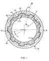
- the annular encoder shown in Figure 1 has a cut metal disc 1 whose inner circumference has a plurality of teeth 11 whose opposite sides 12, 13, are located in radial planes of opening angle passing through the axis O of the disc.
- each tooth 11 are curvilinear in correspondence with portions of arc centered on the axis O of the part.
- each tooth 21 is separated by a radial clearance j2 and j1 from the top 14 and from the bottom 15 of the adjacent tooth 11.
- each point of the disc 11 moves radially and the clearances j1 and j2 vary without creating circumferential stresses in the ring.
- the metal disc 1 also has a stripped external (fig. 1 or 2) or internal (fig. 5, 6) part intended for the production of encoder mounting surfaces during a stamping operation.
- FIG. 3 schematically represents the manufacturing mold 5, the parts 5a, 5b of which contain the imprint for receiving the toothed annular disc 1 and the cavity for receiving the thermoplastic material intended for overmolding the ring 2.
- thermoplastic ring 2 is advantageously molded inside the annular disc 1.
- the radial clearance j1 and j2 then forms during the cooling of the ring 2 by natural shrinking of the material after molding.
- Figures 5, 6 describe an annular encoder in which the outer thermoplastic ring 2 also has a ferrite load so as to produce a multipolar magnetic ring.
- the overmolding process of the ring 2 requires the making of a mold imprint specific to the formation of the sets j1 and J2.
- the metal disc 1 After magnetization of the ring, it is carried out at the bare outer or central part of the disc 1 fixing or hanging on a rotating support.
- the metal disc 1 has an outer mounting surface 18 shown in Figure 4 or an inner surface 20 shown in Figure 6 preserving the radial spacing j1 between the mounting surface and the outer periphery (Fig. 4 ) or internal (fig. 5) of the ring 2.
- This bearing can be achieved by stamping folding of the stripped part of the disc before molding.
Landscapes
- Physics & Mathematics (AREA)
- General Physics & Mathematics (AREA)
- Transmission And Conversion Of Sensor Element Output (AREA)
Abstract
Description
- L'invention a pour objet un codeur annulaire composite constitué par un disque métallique annulaire qui possède une denture enrobée par une matière thermoplastique séparée du sommet et du fond de la denture par un jeu radial.
- L'invention a aussi pour objet un codeur annulaire composite rigide réalisé par assemblage d'un disque métallique avec une matière thermoplastique exempt de contraintes internes.
- L'invention a encore pour objet le procédé de fabrication d'un codeur magnétique annulaire multipolaire assemblé, constitué par un élément thermoplastique moulé chargé de ferrite magnétisée et par un disque annulaire denté concentrique qui possède une portée de montage réalisée par emboutissage du corps du disque.
- Un tel codeur magnétique trouve principalement une application dans les roulements à capteurs d'informations dans le but de créer un générateur d'impulsions.
- Selon l'invention, on place dans l'empreinte d'un moule le disque annulaire denté soumis, si besoin était, à une opération préalable d'emboutissage pliage de la partie dénudée dans lequel on injecte la matière thermoplastique qui se répartit concentriquement au disque et entre la denture de celui-ci pour réaliser un anneau surmoulé séparé de chaque fond et sommet de dent du disque par un jeu radial avant de lui faire subir un processus de magnétisation.
- La résistance mécanique et la précision de la liaison entre le disque et l'anneau sont alors parfaitement assurées. L'avantage du procédé réside dans le fait qu'il évite la création de contraintes résiduelles consécutives au procédé de moulage et permet la dilatation différentielle du disque et de l'anneau imbriquées sans fausser le positionnement, ni créer de contraintes dans les matériaux en présence.
- Le codeur annulaire ainsi obtenu peut être monté sur tout organe extérieur par l'intermédiaire du disque métallique, ce dernier se montant sur l'organe indifféramment par frettage, collage, rivetage ou tout autre procédé connu.
- D'autres avantages de l'invention apparaîtront à la lecture de la description qui suit, faite en référence au dessin annexé dans lequel :
- La figure 1 est une vue en coupe axiale du codeur annulaire,
- La figure 2 est une vue en coupe radiale à plus grande échelle du codeur selon la ligne II-II de la figure 1,
- La figure 3 est une représentation schématique du moule de fabrication du codeur représenté à la figure 1,
- La figure 4 est une vue en coupe radiale du codeur magnétique avec une portée de montage réalisée à la périphérie du disque métallique,
- La figure 5 est une vue en coupe axiale d'une variante de réalisation du codeur,
- La figure 6 est une vue en coupe radiale du codeur selon la ligne VI-VI de la figure 5,
- La figure 7 est un schéma synoptique des phases de réalisation du codeur.
- Le codeur annulaire représenté à la figure 1 possède un disque métallique 1 découpé dont la circonférence intérieure possède une pluralité des dents 11 dont les flancs opposés 12, 13, sont situés dans des plans radiaux d'angle ouverturepassant par l'axe O du disque.

- Le sommet 14 et le fond 15 de chaque dent 11 sont curvilignes en correspondance avec des portions d'arc centré sur l'axe O de la pièce.
- Dans le disque est encastré un anneau plastique 2 moulé portant des dents périphériques 21 dont les flancs opposés 22, 23 sont en appui sur les flancs correspondants des dents 11. Le fond et le sommet de chaque dent 21 sont séparés par un jeu radial j2 et j1 du sommet 14 et du fond 15 de la dent 11 adjacente.
- A la suite d'une dilatation différentielle entre le disque 1 et l'anneau 2, chaque point du disque 11 se déplace radialement et les jeux j1 et j2 varient sans création de contraintes circonférentielles dans l'anneau.
- Le maintien axial de l'anneau plastique 2 est assuré conformément à la figure 2 par des couronnes circulaires 24, 25, disposées axialement de part et d'autre des dents 11 et moulées avec ledit anneau.
- Le disque métallique 1 possède également une partie dénudée extérieure (fig. 1 ou 2) ou intérieure (fig. 5, 6) destinée à la réalisation de portées de montage du codeur au cours d'une opération d'emboutissage.
- La figure 3 représente schématiquement le moule de fabrication 5 dont les parties 5a, 5b contiennent l'empreinte de réception du disque annulaire denté 1 et la cavité de réception de la matière thermoplastique destinée au surmoulage de l'anneau 2.
- La mise en oeuvre du procédé s'applique avantageusement au disque annulaire 1 avec une denture intérieure conformément aux figures 1, 2, 4.
- L'anneau thermoplastique 2 est avantageusement moulé à l'intérieur du disque annulaire 1.
- Le jeu radial j1 et j2 se forme alors au cours du refroidissement de l'anneau 2 par rétreint naturel de la matière après moulage.
- Les figures 5, 6 décrivent un codeur annulaire dans lequel l'anneau thermoplastique extérieur 2 possède également une charge de ferrite de manière à réaliser un anneau magnétique multipolaire.
- Selon cette variante de réalisation, le procédé de surmoulage de l'anneau 2 nécessite la confection d'une empreinte de moule spécifique à la formation des jeux j1 et J2.
- Après magnétisation de l'anneau, on réalise au niveau de la partie nue extérieure ou centrale du disque 1 la fixation ou l'accrochage sur un support tournant. A cet effet, le disque métallique 1 possède une portée 18 de montage extérieure représentée à la figure 4 ou une portée intérieure 20 représentée à la figure 6 en préservant l'écartement radial j1 entre la portée de montage et la périphérie externe (fig. 4) ou interne (fig. 5) de l'anneau 2. Cette portée peut être réalisée par emboutissage pliage de la partie dénudée du disque avant moulage.
- La sélection de la charge de ferrite et le procédé de magnétisation de celle-ci ne font pas partie de la présente invention. On se référera par exemple à la publication US-A 3 169 567 qui décrit une composition de la matière convenable pour l'anneau et son procédé de magnétisation.
- La figure 7 illustre le procédé de fabrication du codeur représenté par les phases successives principales :
- 40 découpage et emboutissage éventuel du disque 1,
- 50 moulage injection de l'anneau 2,
- 60 magnétisation,
Claims (4)
Applications Claiming Priority (2)
| Application Number | Priority Date | Filing Date | Title |
|---|---|---|---|
| FR9002251 | 1990-02-23 | ||
| FR9002251A FR2658908B1 (fr) | 1990-02-23 | 1990-02-23 | Codeur annulaire composite et procede de fabrication de celui-ci. |
Publications (2)
| Publication Number | Publication Date |
|---|---|
| EP0444978A2 true EP0444978A2 (fr) | 1991-09-04 |
| EP0444978A3 EP0444978A3 (en) | 1991-09-18 |
Family
ID=9394062
Family Applications (1)
| Application Number | Title | Priority Date | Filing Date |
|---|---|---|---|
| EP19910400206 Withdrawn EP0444978A3 (en) | 1990-02-23 | 1991-01-29 | Composite annular encoder and method for it's production |
Country Status (3)
| Country | Link |
|---|---|
| US (1) | US5120588A (fr) |
| EP (1) | EP0444978A3 (fr) |
| FR (1) | FR2658908B1 (fr) |
Cited By (1)
| Publication number | Priority date | Publication date | Assignee | Title |
|---|---|---|---|---|
| FR2783914A1 (fr) * | 1998-09-25 | 2000-03-31 | Soc D Mecanique Et De Plastiqu | Procede de realisation d'un codeur magnetique et codeur obtenu par ce procede |
Families Citing this family (5)
| Publication number | Priority date | Publication date | Assignee | Title |
|---|---|---|---|---|
| FR2694082B1 (fr) * | 1992-07-23 | 1994-09-16 | Skf France | Codeur annulaire composite pour roulement et roulement à capteur d'informations, comportant un tel codeur. |
| DE10356224A1 (de) * | 2003-12-02 | 2005-06-30 | Pwb-Ruhlatec Industrieprodukte Gmbh | Taktscheibenbefestigung |
| CN101524929B (zh) * | 2008-03-04 | 2011-05-18 | 中国印钞造币总公司 | 号码机字轮的编码装置及编码方法 |
| DE102012010606B4 (de) * | 2012-05-30 | 2014-07-03 | Carl Freudenberg Kg | Encoderring |
| DE102012010604B4 (de) * | 2012-05-30 | 2014-02-27 | Carl Freudenberg Kg | Encoderring |
Family Cites Families (8)
| Publication number | Priority date | Publication date | Assignee | Title |
|---|---|---|---|---|
| US1780710A (en) * | 1927-01-26 | 1930-11-04 | Kattwinkel Hans | Friction body for friction couplings, brakes, and the like |
| US1754233A (en) * | 1927-03-09 | 1930-04-15 | Russell Mfg Co | Friction element |
| FR2117731B2 (fr) * | 1967-10-11 | 1974-08-23 | Anvar | |
| US3654777A (en) * | 1970-11-25 | 1972-04-11 | Minnesota Mining & Mfg | Torque transmitting device |
| GB2156474A (en) * | 1984-03-30 | 1985-10-09 | Stephen Timothy Scott | Conversion of chain sprocket to toothed belt pulley |
| JPS6131764A (ja) * | 1984-07-20 | 1986-02-14 | Konishiroku Photo Ind Co Ltd | 段付歯車 |
| EP0186261A1 (fr) * | 1984-11-24 | 1986-07-02 | Automotive Products Public Limited Company | Matériau de friction et disque porteur |
| JPS62242155A (ja) * | 1986-04-14 | 1987-10-22 | Toshiba Corp | フライホイ−ル及びその製造方法 |
-
1990
- 1990-02-23 FR FR9002251A patent/FR2658908B1/fr not_active Expired - Fee Related
-
1991
- 1991-01-04 US US07/637,463 patent/US5120588A/en not_active Expired - Fee Related
- 1991-01-29 EP EP19910400206 patent/EP0444978A3/fr not_active Withdrawn
Cited By (1)
| Publication number | Priority date | Publication date | Assignee | Title |
|---|---|---|---|---|
| FR2783914A1 (fr) * | 1998-09-25 | 2000-03-31 | Soc D Mecanique Et De Plastiqu | Procede de realisation d'un codeur magnetique et codeur obtenu par ce procede |
Also Published As
| Publication number | Publication date |
|---|---|
| US5120588A (en) | 1992-06-09 |
| EP0444978A3 (en) | 1991-09-18 |
| FR2658908A1 (fr) | 1991-08-30 |
| FR2658908B1 (fr) | 1993-12-17 |
Similar Documents
| Publication | Publication Date | Title |
|---|---|---|
| FR2498494A1 (fr) | Procede et appareil pour la fabrication d'une rotule et rotule ainsi obtenue | |
| FR2625280A1 (fr) | Soufflet pour recouvrir et etancher l'espace libre entre les parties d'un joint d'articulation homocinetique ou analogue | |
| EP0444978A2 (fr) | Codeur annulaire composite et procédé de fabrication de celui-ci | |
| FR2661227A1 (fr) | Procede de realisation d'un arbre, en particulier d'un arbre de cardan, forme d'un assemblage d'un tube de matiere synthetique armee de fibres et d'un element de raccordement en materiau rigide. | |
| FR2582768A1 (fr) | Support de faible epaisseur de matiere pour une bague de synchronisation | |
| EP1832852A1 (fr) | Codeur pour arbre, dispositif comprenant un tel codeur et procédé de fabrication d'un tel codeur. | |
| FR2466533A1 (fr) | Rotor de filature a fibres liberees, comportant un corps de base et un corps rotorique | |
| FR2533083A1 (fr) | Rotor pour moteurs synchrones | |
| FR2463040A1 (fr) | Direction hydraulique a cremaillere | |
| EP1418371B1 (fr) | Joint dynamique pour arbre rotatif muni d'un dispositif de codage angulaire, dispositif comportant un tel joint et procédé de fabrication d'un tel joint | |
| EP0230843B1 (fr) | Système de fixation d'une bague annulaire | |
| EP1632752B1 (fr) | Codeur de déplacement, dispositif comprenant un tel codeur et procédé de fabrication d'un tel codeur | |
| EP0704357A1 (fr) | Platine-support pour un mécanisme d'essuie-glace | |
| FR2698945A1 (fr) | Organe de transmission mécanique du type comportant un arbre et une roue dentée et moteur d'essuie-glace comportant un tel organe mécanique. | |
| EP0612650B1 (fr) | Arbre de direction télescopique par exemple pour véhicule automobile | |
| FR2748809A1 (fr) | Support de palier | |
| FR2460414A1 (fr) | Dispositif destine a compenser le jeu radial d'un roulement dans un alesage de palier au moyen d'un disque comportant un bord en forme de coin | |
| EP0480844B1 (fr) | Perfectionnements aux capteurs pourvus d'un surmoulage, notamment aux capteurs de vitesse pour véhicules automobiles | |
| FR2469610A1 (fr) | Perfectionnements aux elements de machines associes a un arbre tournant, notamment roues de ventilateur | |
| FR2697304A1 (fr) | Corps de palier en matière plastique. | |
| FR2642124A3 (fr) | Douille de transport et de montage | |
| EP0549452B1 (fr) | Couronne denteé pour un capteur magnétique de vitesse d'une roue | |
| EP1733189B1 (fr) | Codeur pour arbre, dispositif comprenant un tel codeur et procede de fabrication d'un tel codeur | |
| FR2663390A1 (fr) | Procede permettant de simplifier la fabrication des dentures d'engrenages. | |
| EP0607828B1 (fr) | Moteur électromagnétique du type pas à pas, comportant une cage engagée dans un stator |
Legal Events
| Date | Code | Title | Description |
|---|---|---|---|
| PUAI | Public reference made under article 153(3) epc to a published international application that has entered the european phase |
Free format text: ORIGINAL CODE: 0009012 |
|
| PUAL | Search report despatched |
Free format text: ORIGINAL CODE: 0009013 |
|
| AK | Designated contracting states |
Kind code of ref document: A2 Designated state(s): DE ES GB IT SE |
|
| AK | Designated contracting states |
Kind code of ref document: A3 Designated state(s): DE ES GB IT SE |
|
| 17P | Request for examination filed |
Effective date: 19920221 |
|
| 17Q | First examination report despatched |
Effective date: 19930614 |
|
| STAA | Information on the status of an ep patent application or granted ep patent |
Free format text: STATUS: THE APPLICATION HAS BEEN WITHDRAWN |
|
| 18W | Application withdrawn |
Withdrawal date: 19930723 |