EP0444997B1 - Steuerschaltung für die Energieversorgung einer Mehrzahl elektronischer Module - Google Patents
Steuerschaltung für die Energieversorgung einer Mehrzahl elektronischer Module Download PDFInfo
- Publication number
- EP0444997B1 EP0444997B1 EP91400432A EP91400432A EP0444997B1 EP 0444997 B1 EP0444997 B1 EP 0444997B1 EP 91400432 A EP91400432 A EP 91400432A EP 91400432 A EP91400432 A EP 91400432A EP 0444997 B1 EP0444997 B1 EP 0444997B1
- Authority
- EP
- European Patent Office
- Prior art keywords
- circuit
- modules
- line
- supply
- data bus
- Prior art date
- Legal status (The legal status is an assumption and is not a legal conclusion. Google has not performed a legal analysis and makes no representation as to the accuracy of the status listed.)
- Expired - Lifetime
Links
Images

Classifications
-
- H—ELECTRICITY
- H02—GENERATION; CONVERSION OR DISTRIBUTION OF ELECTRIC POWER
- H02J—ELECTRIC POWER NETWORKS; CIRCUIT ARRANGEMENTS OR SYSTEMS FOR SUPPLYING OR DISTRIBUTING ELECTRIC POWER; SYSTEMS FOR STORING ELECTRIC ENERGY
- H02J1/00—Circuit arrangements for DC mains or DC distribution networks
- H02J1/14—Balancing load and power generation in DC networks
-
- B—PERFORMING OPERATIONS; TRANSPORTING
- B60—VEHICLES IN GENERAL
- B60R—VEHICLES, VEHICLE FITTINGS, OR VEHICLE PARTS, NOT OTHERWISE PROVIDED FOR
- B60R16/00—Electric or fluid circuits specially adapted for vehicles and not otherwise provided for; Arrangement of elements of electric or fluid circuits specially adapted for vehicles and not otherwise provided for
- B60R16/02—Electric or fluid circuits specially adapted for vehicles and not otherwise provided for; Arrangement of elements of electric or fluid circuits specially adapted for vehicles and not otherwise provided for electric constitutive elements
- B60R16/03—Electric or fluid circuits specially adapted for vehicles and not otherwise provided for; Arrangement of elements of electric or fluid circuits specially adapted for vehicles and not otherwise provided for electric constitutive elements for supply of electrical power to vehicle subsystems or for
- B60R16/0315—Electric or fluid circuits specially adapted for vehicles and not otherwise provided for; Arrangement of elements of electric or fluid circuits specially adapted for vehicles and not otherwise provided for electric constitutive elements for supply of electrical power to vehicle subsystems or for using multiplexing techniques
-
- H—ELECTRICITY
- H02—GENERATION; CONVERSION OR DISTRIBUTION OF ELECTRIC POWER
- H02J—ELECTRIC POWER NETWORKS; CIRCUIT ARRANGEMENTS OR SYSTEMS FOR SUPPLYING OR DISTRIBUTING ELECTRIC POWER; SYSTEMS FOR STORING ELECTRIC ENERGY
- H02J2105/00—Networks for supplying or distributing electric power characterised by their spatial reach or by the load
- H02J2105/30—Networks for supplying or distributing electric power characterised by their spatial reach or by the load the load networks being external to vehicles, i.e. exchanging power with vehicles
- H02J2105/33—Networks for supplying or distributing electric power characterised by their spatial reach or by the load the load networks being external to vehicles, i.e. exchanging power with vehicles exchanging power with road vehicles
Definitions
- the present invention relates to a device for controlling the electrical supply of a plurality of electronic modules and, more particularly, to such a device making it possible to selectively control this supply depending on whether the device is in standby state or when active state.
- Today's motor vehicles are increasingly loaded with electronic modules associated with sensors and actuators to provide control functions for organs such as headlights, wipers, displays of on-board computers, etc. fuel injection control in an internal combustion engine propelling the vehicle, adaptive suspension control or anti-lock of the vehicle wheels. It is now envisaged to electrically supply these modules with a common supply line or bus and to interconnect the modules with a local multiplexed communications system comprising a data bus common to all the modules.
- Publication EP-A-0 327 456 proposes the operational state and a standby state of the electronic boxes by means of messages circulating in a communication channel to which these boxes are connected. For this, it is necessary to stop supplying the modules via the supply bus by isolating the latter from the battery. When the system is thus put in the "standby" state, it is however necessary that the request for certain functions is capable of "waking up” the entire system. This is the case, for example, when the driver actuates an ignition key to start the vehicle. It is then necessary that certain parts of the modules remain supplied in standby state, to allow the system to "wake up”.
- the threshold is then a function of the number of modules or stations which are likely to wake up the system. This threshold must then be adjusted according to the "options" present in the vehicle, options which are known to be chosen arbitrarily by the vehicle owner from a list of options made available by the manufacturer.
- the detection of a current threshold being exceeded does not make it possible to identify the module which is at the origin of the system awakening. Such an identification would however be advantageous in that it would make it possible to seek in priority the function which is at the origin of the alarm clock.
- the present invention therefore aims to provide a device for controlling the electrical supply of a plurality of electronic modules, which does not have these drawbacks of the devices of the prior art.
- the object of the present invention is to produce such a device equipped with means for awakening the entire device which do not require adjustments as a function of the consumption of the modules capable of waking up the device.
- the present invention also aims to produce such a device which is well immune to noise due to electrical and electromagnetic disturbances present in the environment of a motor vehicle.
- Another object of the present invention is to produce such a device which comprises means for identifying the module which is responsible for waking the device.
- data processing center of the type which includes a common power supply line for the modules
- this device being remarkable in that it comprises means installed in the central unit and sensitive to a predetermined state of the device for controlling its setting in the standby state by cutting off the supply of the modules via the common line and then ensuring the electrical supply of at least one circuit for generating wake-up signals forming part of a module, by means of at least a line of the data bus, and means sensitive to the wake-up signals emitted by the circuit for generating such signals, to cut off the supply of the modules by the donation bus and to restore the power supply to the modules via the common power supply line.
- At least one of the modules comprises means for selectively triggering a circuit for generating associated wake-up signals, a coupling circuit associated with this generation circuit for transmitting these signals over the data bus and a detection circuit. interposed between the bus and the central unit and sensitive to these signals to transmit to the central unit control information for waking up the device.
- the device further comprises a voltage regulator put into service by the central unit when the supply of the modules is cut off by the common supply line, to supply the detection circuit and, through the data bus, the circuit coupling and the wake-up signal generation circuit of each module equipped with such circuits.
- the wake-up signal generation circuit generates a pulse sequence, the coupling circuit comprising means for modulating, under the control of this sequence, the current flowing in the line of the data bus used for supplying a part of the module in standby period, the detection circuit being sensitive to this modulated current for transmitting wake-up information to the central unit.
- the modulation means is a transistor whose emitter-collector circuit is connected between ground and the line of the data bus which serves as a supply line in standby period, the circuit for generating wake-up signals controlling the base of this transistor to modulate the current in this line.
- the pulse sequence emitted by a module is specific to it and the central unit comprises means for identifying the module emitting the sequence, from the signal transmitted by the detection circuit.
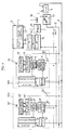
- the control device comprises several electronic modules M1, M2, etc ... powered by a source of continuous electrical energy 1 via two common lines 2, 3 respectively connected to the positive and negative terminals of the source 1.
- the source of electrical energy is constituted by the vehicle battery.
- Lines 2, 3 thus constitute a "supply bus" to which voltage regulators 4, 4 ′, etc. are connected, each forming part of one of the modules M1, M2, respectively, to supply it with power. after awakening of said module, as will be seen in the remainder of this description.
- the modules each provide a specific application.
- an electronic module can be associated with a block of joysticks placed in a motor vehicle near the steering wheel, to allow the driver to control the issuance of activation / deactivation orders of various components of the vehicle.
- Another module can also be associated with an optical unit of the vehicle to process orders of switching on / off of headlights, position lights, etc. All the modules are interconnected with each other and with a central data processing unit 5, as is the case in particular in a "bodywork” or "class A" multiplex network where this unit centralizes the intelligence necessary for the execution of the various functions for controlling headlights, lights, windshield wipers, displaying data on an on-board computer, etc.
- a module M1, M2 includes a protocol controller 6,6 ′ interposed between a data bus 7 common to all the modules and to the central unit 5, and means 8, 8 ′ respectively, each constituting an application circuit specific to the functions performed (switching on or off a bulb, counting pulses to determine the distance traveled and the speed of the vehicle, etc.).
- the data bus is a two-line bus (DATA, DATA ) powered by differential digital signals, in particular for reasons of noise immunity.
- VLSI very high integration wired logic
- modules can be equipped with means designed to trigger the awakening of the entire device, while other modules are not equipped with such means.
- a module associated with the lever block of a motor vehicle must be equipped with such wake-up means because it is in this block that the driver introduces an ignition key to control the starting of the engine. The rotation of this key must cause the device to wake up from a standby state previously established to minimize the power consumption of the vehicle, for example during a standstill thereof.
- Other modules must also be able to wake up the device, for example a module associated with a vehicle defense system against intrusions.
- the invention is particularly interested in the organization of modules such as modules M1 or M2.
- the protocol controller is interconnected to the data bus 7 through a line transceiver 9, 9 ′, possibly associated with filter 10, 10 ′, an isolation circuit 11, 11 ′ from the transmitter -Receiver being further provided for a purpose which will be explained later.
- the latter circuit is itself supplied by the voltage regulator 4, 4 ′, just like the protocol controller 6, 6 ′.
- the modules M1 and M2 further each comprise a circuit for generating wake-up signals 12, 12 ′, respectively, activated by a trigger means such as a switch 13, 13 ′.
- a trigger means such as a switch 13, 13 ′.
- Such a switch can be closed by the introduction of an ignition key into the lock of a lever block of a motor vehicle, as seen above. The introduction of such a key being significant of a starting action of the vehicle, it is then necessary to "wake up" the electronic modules which control various actuators incorporated in this vehicle. According to the invention, this awakening is caused by the emission of a sequence of signals generated by the generation circuit 12 and transmitted to the central unit 5 via a coupling circuit 14 (or 14 ′ in module M2), a detection circuit 15 and a possible filtering circuit 16.
- the electrical consumption of all the modules is reduced during the standby period, by cutting off the supply of these modules by the supply bus 2, 3 and then only supplying the circuits required to wake up the assembly, via the data bus.
- This power supply then replaces that established during a period of complete activity of the modules, by connection lines 22, 22 ′ to line 2 of the power bus.
- the power supply in standby time of the only circuits necessary for the transmission and processing of the wake-up signals makes it possible to considerably reduce the electrical consumption of the modules compared to that which is observed when all the electronic modules are active, (commonly, 2 to 25 amps).
- the central unit 5 thus prevented, opens a disconnector 17 which cuts the connection of the line 2 to the battery 1 and closes a switch 18 to ensure the connection to the battery of a voltage regulator 19 which supplies the line DATA of the data bus, the detection circuit 15 and the filtering circuit 16.
- the circuits 12, 12 ′ and 14, 14 ′ of the modules M1 and M2 respectively are then supplied by the line DATA while the voltage regulators 4, 4 ′ cease to be supplied by the battery, the line 2 being cut. It follows that the protocol controllers 6, 6 ′ and the application circuits 8, 8 ′ normally supplied by the regulators 4, 4 ′ stop being supplied, which greatly reduces the current required from the battery.
- the isolation circuits 11, 11 ′ are normally supplied by the regulators 4, 4 ′ respectively, to ensure the transmission of information coming from the data bus 7 to the protocol controllers 6, 6 ′ respectively.
- the power supply to these circuits is cut off, to prevent the current coming, in standby state, from the DATA line from coming to supply the protocol controllers 6, 6 ′ through line transceivers 9, 9 ′.
- the power supply of the device being thus adjusted for a standby state, only the circuits 12, 12 ′, 14, 14 ′, 15 and 16 remain active.
- the circuit 12 supplied with electrical energy by an ALIM line via the coupling circuit 14, supplies the latter a sequence of "wake-up" signals.
- the coupling circuit 14, which will be described later in detail in connection with FIG. 2, then modulates the supply current which it receives from the line DATA by the control line 15, according to the sequence of signals received from the circuit 12, so as to establish on the line DATA current signals suitable for being read by the detection circuit 15 and filtered by the circuit 16, before being transmitted to the central unit 5 by a line 20.
- the purpose of the filtering is to eliminate parasitic pulses of duration not calibrated, induced by possible electromagnetic interference from the data bus.
- the sequence of signals emitted by the circuit 12 is particular to the module from which it originates and the central unit can then identify this module by recognizing the particular sequence attached to it. This identification gives the central unit the possibility of modulating the awakening of the device as a function of the origin of the awakening action, as we saw above in the preamble to this description.
- a software for "awakening detection” installed in the central unit 5 decodes the sequence of signals received from line 20 and in return commands the closing of the disconnector 17 and the opening of the switch 18, to restore the power supply to the modules via the power bus, as appropriate in normal operation of these modules.
- the central unit includes other software designed to analyze the multiplexed signals received by the data bus 7, to deduce a possible transition to the inactive state of the vehicle and then switch the power supply to this device in the "standby" configuration.
- this software can be sensitive for example, to the absence, for a predetermined time, of signals normally received from certain sensors or actuators, significant absence of inactivity of the vehicle.
- the withdrawal of the ignition key is a significant action of a transition to the inactive state of the vehicle which can be detected and interpreted in this sense by the software for "detection of transition to mode standby".
- this bus in current rather than in voltage because, in the medium highly disturbed from the electromagnetic point of view that constitutes a motor vehicle, it thus overcomes number of parasitic voltage signals induced electromagnetically in the bus by the environment.
- the information circulating on the data bus in the form of current pulses, the role of the line transceivers is to ensure a current / voltage conversion of these pulses to make them intelligible to the protocol controllers and a voltage / current conversion from a controller to the bus.
- FIG. 2 of the appended drawing in which a diagram of a coupling circuit such as circuit 14 of the module M1 has been shown.
- This circuit is connected by a line 22 to line 2 of the power bus connected to the positive pole of the battery 1.
- the circuit is also connected to the line DATA from the data bus 7 via line 21 and supplies the generation circuit 12 with wake-up signals via the line ALIM, this circuit 12 delivering corresponding pulses IMP to the coupling circuit, to modulate the current in the line DATA as will be explained later.
- the generation circuit 12 requires a reset synchronous RESET with the passage of the device in standby state.
- line 22 goes to a low voltage level and this level is transmitted to the reset input of the circuit 12 by a line 23, through a filtering circuit (C1, R2) capable of absorbing the voltage pulse which appears when the vehicle engine is started.
- Load resistors R1 and R7 are introduced between line 22 and line 23 on the one hand, between the filter inlet (C1, R2) and ground on the other hand.
- Line 22 is connected to the supply line ALIM of circuit 12 via a diode D1.
- a Zener diode Z1 of 10 volts breakdown voltage for example, protects circuit 12 from overvoltages on line 22. Realized in current CMOS technology, circuit 12 can withstand voltages up to 18 volts. It is therefore well protected by the Zener diode Z1.
- a capacitor C2 is placed in parallel on the diode Z1, between the input ALIM of the circuit 12 and the ground. Capacity C2 filters out transient disturbances in the supply.
- the power to circuit 12 is provided by the line DATA connected to the ALIM input of the circuit via a diode D2 and a resistor R6 forming part of a filtering circuit (C2, R6).
- This supply voltage is +5 volts for example.
- the diode Z1 is then blocked and does not consume.
- Diode D1 is also blocked and prevents the passage of current from the line DATA to line 22.
- the diode D1 prevents the supply voltage of circuit 12 from following the voltage of the battery when it drops suddenly (when starting the vehicle for example) and then ensures the diode D2 blocked.
- the actual coupling section of circuit 14 is constituted by a transistor T1, of the NPN type for example, whose collector-emitter circuit is connected between the line DATA and mass.
- a load resistor R3 is placed on the collector of transistor T1.
- the base of transistor T1 is connected to the midpoint of a voltage divider made up of resistors (R4, R5), a capacitance C3 transmitting to this bridge the voltage pulses IMP constituting a sequence of wake-up pulses emitted by the circuit 12 following the closing of the switch 13 (see FIG. 1).
- the capacity C3 has the function of blocking the consumption of the circuit 12 if the output of the latter blocks in logic state 1.
- transistor T1 is modulated by the wake-up pulses IMP.
- the transistor T1 then modulates the current in the line in accordance with these pulses.
- DATA DATA .
- the current pulses thus introduced on this line are read by the detection circuit 15 and filtered by the circuit 16 which delivers to the central unit 5 logic signals which are decoded by the latter and converted into a command to wake up the device. according to the invention, by closing the disconnector 17.
- the values of the resistors R3, R4 and R5 can be chosen so that the transistor T1 establishes a current pulse of 27 mA amplitude in the line.
- DATA when the signal delivered by the output IMP of circuit 12 is at logic level 1.
- the capacity C3 can be chosen so as to limit the current consumption to a time interval of 10 ms, in the event of blocking of the input IMP at the high state.
Landscapes
- Engineering & Computer Science (AREA)
- Power Engineering (AREA)
- Selective Calling Equipment (AREA)
- Remote Monitoring And Control Of Power-Distribution Networks (AREA)
- Small-Scale Networks (AREA)
Claims (12)
- Vorrichtung zur Steuerung der elektrischen Versorgung einer Vielzahl elektronischer Module (M1, M2), die über einen Datenbus (7) mit einer zentralen Datenverarbeitungseinheit (5) verbunden sind, die eine gemeinsame elektrische Versorgungsleitung (2) für die Module aufweist, dadurch gekennzeichnet, daß sie eine in der zentralen Einheit (5) eingebaute Anordnung aufweist, welche auf einen vorgegebenen Zustand der Vorrichtung reagiert zur Überführung in den Überwachungszustand durch Unterbrechen der Versorgung der Module (M1, M2) über die gemeinsame Leitung (2) und dadurch Sicherstellung der elektrischen Versorgung wenigstens eines Schaltkreises (12, 12′) zur Erzeugung von Einschaltsignalen, welcher Teil eines Moduls ist, mittels wenigstens einer Datenbusleitung (
DATA ) sowie eine Anordnung (15, 16, 5) aufweist, die auf die vom Schaltkreis (12, 12′) zur Erzeugung dieser Signale abgegebenen Einschaltsignale reagiert, um die Versorgung der Module über den Datenbus (7) zu unterbrechen und die Versorgung der Module über die gemeinsame elektrische Versorgungsleitung (2) wiederherzustellen. - Vorrichtung nach Anspruch 1, dadurch gekennzeichnet, daß die zentrale Einheit (5) programmierte Schaltungen aufweist, um einen Überwachungszustand festzustellen, ausgehend von einer Verarbeitung von Informationen, welche von den Modulen abgegeben werden und der zentralen Einheit (5) über den Datenbus (7) zugeführt werden.
- Vorrichtung nach Anspruch 2, dadurch gekennzeichnet, daß wenigstens eines der Module eine Anordnung (13, 13′) aufweist, um wahlweise einen zugeordneten Schaltkreis (12, 12′) zur Erzeugung von Einschaltsignalen auszulösen, einen Kopplungsschaltkreis (14, 14′) aufweist, der diesem Schaltkreis zur Erzeugung zugeordnet ist, um diese Signale dem Datenbus (7) zuzuführen und einen Meaßchaltkreis (15) aufweist, der zwischen dem Bus (7) und der zentralen Einheit (5) vorgesehen ist und der auf diese Signale reagiert, um der zentralen Einheit (5) eine Steuerinformation für das Einschalten der Vorrichtung zuzuführen.
- Vorrichtung nach Anspruch 3, dadurch gekennzeichnet, daß sie einen Spannungsregler (19) aufweist, der durch die zentrale Einheit (5) beim Unterbrechen der Versorgung der Module durch die gemeinsame Versorgungsleitung (2) eingeschaltet wird, um den Meißschaltkreis (15) zu versorgen und über den Datenbus (7) den Kopplungsschaltkreis (14, 14′) sowie den Schaltkreis (12, 12′) zur Erzeugung der Einschaltsignale für jedes mit derartigen Schaltkreisen versehene Modul.
- Vorrichtung nach einem der Ansprüche 3 und 4, dadurch gekennzeichnet, daß jedes der Module (M1, M2) außerdem einen Schaltkreis (11, 11′) aufweist, der durch den Übergang in den Überwachungszustand der Vorrichtung angesteuert wird, um den Rest des Moduls von der durch den Datenbus (7) realisierten Versorgung zu isolieren.
- Vorrichtung nach Anspruch 5, dadurch gekennzeichnet, daß jedes der Module (M1, M2) eine Kontrollschaltung (6, 6′) aufweist, die mit dem Datenbus (7) über einen Sender-Empfänger (9, 9′) verbunden ist, wobei der Isolierschaltkreis (11, 11′) das Einschalten oder Ausschalten dieses Sender-Empfängers (9, 9′) ansteuert.
- Vorrichtung nach Anspruch 3, dadurch gekennzeichnet, daß der Schaltkreis (12, 12′) zur Erzeugung der Einschaltsignale eine Impulsfolge erzeugt und daß der Kopplungsschaltkreis (14, 14′) eine Anordnung (T1) aufweist, um unter der Steuerung dieser Folge den in der Datenbusleitung (
DATA ) fließenden Strom zu modulieren, welcher zur Versorgung eines Teils des Moduls im Überwachungszustand verwendet wird, wobei der Meßschaltkreis (15) auf diesen modulierten Strom reagiert, um der zentralen Einheit eine Einschaltinformation zuzuführen. - Vorrichtung nach Anspruch 7, dadurch gekennzeichnet, daß die Modulationsanordnung ein Transistor (T1) ist, dessen Emitter-Kollektor-Schaltkreis zwischen der Masse und der Datenbusleitung (7) angeschlossen ist, die als Versorgungsleitung wahrend der Überwachungsperiode dient, wobei der Schaltkreis (12, 12′) zur Erzeugung der Einschaltsignale die Basis des Transistors (T1) steuert, um den Strom in der Leitung zu modulieren.
- Vorrichtung nach Anspruch 8, dadurch gekennzeichnet, daß die von einem Modul abgegebene Impulsfolge für dieses eigenartig ist und daß die zentrale Einheit (5) eine Anordnung aufweist zur Identifizierung des die Folge abgebenden Moduls, ausgehend von Signalen (IMP), die vom Meßschaltkreis (15) stammen.
- Vorrichtung nach einem der Ansprüche 3 bis 9, dadurch gekennzeichnet, daß der Kopplungsschaltkreis (14, 14′) auf die Unterbrechung der Versorgung der gemeinsamen Leitung (2) reagiert, um den Schaltkreis (12, 12′) zur Erzeugung der Einschaltsignale einzuschalten.
- Vorrichtung nach einem der Ansprüche 3 bis 10, dadurch gekennzeichnet, daß die Anordnung zur wahlweisen Auslösung eines Schaltkreises (12, 12′) zur Erzeugung der Einschaltsignale aus einem Unterbrecher (13, 13′) besteht, dessen Umschaltung die Einschaltung dieses Schaltkreises bewirkt, wobei die Umschaltung dieses Unterbrechers durch eine Aktion ausgelöst wird, welche ein Einschalten der Vorrichtung beinhaltet.
- Vorrichtung nach Anspruch 11, angepaßt an das Netz in einem Kraftfahrzeug, dadurch gekennzeichnet, daß der Unterbrecher (13, 13′) umgeschaltet wird durch die Einfführung eines Zündschlüssels in ein Zündschloß vor dem Starten des Fahrzeuges.
Applications Claiming Priority (2)
| Application Number | Priority Date | Filing Date | Title |
|---|---|---|---|
| FR9002570 | 1990-03-01 | ||
| FR9002570A FR2659155B1 (fr) | 1990-03-01 | 1990-03-01 | Dispositif de commande de l'alimentation electrique d'une pluralite de modules electroniques. |
Publications (2)
| Publication Number | Publication Date |
|---|---|
| EP0444997A1 EP0444997A1 (de) | 1991-09-04 |
| EP0444997B1 true EP0444997B1 (de) | 1995-02-01 |
Family
ID=9394273
Family Applications (1)
| Application Number | Title | Priority Date | Filing Date |
|---|---|---|---|
| EP91400432A Expired - Lifetime EP0444997B1 (de) | 1990-03-01 | 1991-02-19 | Steuerschaltung für die Energieversorgung einer Mehrzahl elektronischer Module |
Country Status (4)
| Country | Link |
|---|---|
| EP (1) | EP0444997B1 (de) |
| DE (1) | DE69107100T2 (de) |
| ES (1) | ES2067880T3 (de) |
| FR (1) | FR2659155B1 (de) |
Cited By (15)
| Publication number | Priority date | Publication date | Assignee | Title |
|---|---|---|---|---|
| US7095321B2 (en) | 2003-04-14 | 2006-08-22 | American Power Conversion Corporation | Extensible sensor monitoring, alert processing and notification system and method |
| US7148796B2 (en) | 2003-04-14 | 2006-12-12 | American Power Conversion Corporation | Environmental monitoring device |
| US7159022B2 (en) | 2001-01-26 | 2007-01-02 | American Power Conversion Corporation | Method and system for a set of network appliances which can be connected to provide enhanced collaboration, scalability, and reliability |
| US7330886B2 (en) | 1999-10-27 | 2008-02-12 | American Power Conversion Corporation | Network appliance management |
| US7392309B2 (en) | 1999-10-27 | 2008-06-24 | American Power Conversion Corporation | Network appliance management |
| US7542963B2 (en) | 2003-04-14 | 2009-06-02 | American Power Conversion Corporation | Method and system for journaling and accessing sensor and configuration data |
| US7627651B2 (en) | 2003-10-27 | 2009-12-01 | American Power Conversion Corporation | System and method for network device communication |
| US7779026B2 (en) | 2002-05-03 | 2010-08-17 | American Power Conversion Corporation | Method and apparatus for collecting and displaying network device information |
| US8005944B2 (en) | 1999-10-27 | 2011-08-23 | American Power Conversion Corporation | Method and system for monitoring computer networks and equipment |
| US8271626B2 (en) | 2001-01-26 | 2012-09-18 | American Power Conversion Corporation | Methods for displaying physical network topology and environmental status by location, organization, or responsible party |
| US8566292B2 (en) | 2003-04-14 | 2013-10-22 | Schneider Electric It Corporation | Method and system for journaling and accessing sensor and configuration data |
| US8990536B2 (en) | 2011-06-01 | 2015-03-24 | Schneider Electric It Corporation | Systems and methods for journaling and executing device control instructions |
| US9952103B2 (en) | 2011-12-22 | 2018-04-24 | Schneider Electric It Corporation | Analysis of effect of transient events on temperature in a data center |
| US11076507B2 (en) | 2007-05-15 | 2021-07-27 | Schneider Electric It Corporation | Methods and systems for managing facility power and cooling |
| FR3137512A1 (fr) * | 2022-07-04 | 2024-01-05 | Stmicroelectronics (Rousset) Sas | Alimentation d'un dispositif électronique |
Families Citing this family (15)
| Publication number | Priority date | Publication date | Assignee | Title |
|---|---|---|---|---|
| DE4125860C1 (de) * | 1991-08-03 | 1992-08-06 | Robert Bosch Gmbh, 7000 Stuttgart, De | |
| JP2949998B2 (ja) * | 1992-02-21 | 1999-09-20 | 日産自動車株式会社 | 通信装置 |
| US5389952A (en) * | 1992-12-02 | 1995-02-14 | Cordata Inc. | Low-power-consumption monitor standby system |
| US5821924A (en) * | 1992-09-04 | 1998-10-13 | Elonex I.P. Holdings, Ltd. | Computer peripherals low-power-consumption standby system |
| FR2701325B1 (fr) * | 1993-02-05 | 1995-03-10 | Renault | Dispositif d'isolement de bus de transmission de données. |
| JP3136926B2 (ja) * | 1994-11-08 | 2001-02-19 | 松下電器産業株式会社 | 蓄電池の状態管理システム |
| EP1266802B1 (de) * | 1995-05-24 | 2003-11-12 | Hitachi, Ltd. | System und Verfahren zur elektronischen Kraftfahrzeugsteuerung |
| KR20000016166A (ko) * | 1997-04-01 | 2000-03-25 | 클라우스 포스, 게오르그 뮐러 | 차량에서 제어장치를 작동하기 위한 시스템 |
| DE19715880C1 (de) * | 1997-04-16 | 1998-07-23 | Mc Micro Compact Car Ag | System aus drahtbusvernetzten Steuergeräten mit verringertem Ruhestrombedarf |
| DE19853451B4 (de) * | 1998-11-19 | 2007-06-14 | Robert Bosch Gmbh | Verfahren zum Deaktivieren eines Netzwerkkomponentenverbundes, insbesondere eines Kraftfahrzeug-Netzwerkkomponentenverbundes |
| DE10031891A1 (de) | 2000-06-30 | 2002-01-10 | Bosch Gmbh Robert | Verfahren zum Betrieb von einem an ein Fahrzeugkommunikationsnetz angeschlossenen Geräts |
| FR2911442B1 (fr) | 2007-01-16 | 2015-05-15 | Airbus France | Systeme et procede d'alimentation en puissance pour les actionneurs a bord d'un aeronef |
| CN101950281B (zh) * | 2010-07-06 | 2015-11-25 | 无锡中星微电子有限公司 | 一种控制协处理器的方法和装置 |
| FR3043961B1 (fr) | 2015-11-23 | 2017-11-17 | Continental Automotive France | Procede de gestion de l'alimentation d'une unite de commande electronique pendant la phase de demarrage d'un vehicule automobile |
| FR3047573B1 (fr) * | 2016-02-10 | 2018-03-02 | Continental Automotive France | Procede de commande en tension d'un equipement monte dans un vehicule automobile |
Family Cites Families (5)
| Publication number | Priority date | Publication date | Assignee | Title |
|---|---|---|---|---|
| FR2445769A1 (fr) * | 1979-01-04 | 1980-08-01 | Renault | Dispositif de distribution d'energie electrique a bord d'un vehicule, par exemple a moteur |
| US4661718A (en) * | 1984-06-07 | 1987-04-28 | Nippondenso Co., Ltd. | Information and electrical power transmission system and method for vehicle |
| US4639609A (en) * | 1985-02-26 | 1987-01-27 | United Technologies Automotive, Inc. | Load current management system for automotive vehicles |
| FR2578067B1 (fr) * | 1985-02-27 | 1988-04-15 | Renault | Systeme de distribution commandee d'energie electrique dans un vehicule automobile |
| FR2626998B1 (fr) * | 1988-02-05 | 1990-08-03 | Bendix Electronics Sa | Systeme de mise en etat operationnel et en etat de veille de boitiers electroniques connectes a un canal de communication |
-
1990
- 1990-03-01 FR FR9002570A patent/FR2659155B1/fr not_active Expired - Lifetime
-
1991
- 1991-02-19 EP EP91400432A patent/EP0444997B1/de not_active Expired - Lifetime
- 1991-02-19 ES ES91400432T patent/ES2067880T3/es not_active Expired - Lifetime
- 1991-02-19 DE DE69107100T patent/DE69107100T2/de not_active Expired - Fee Related
Cited By (28)
| Publication number | Priority date | Publication date | Assignee | Title |
|---|---|---|---|---|
| US8005944B2 (en) | 1999-10-27 | 2011-08-23 | American Power Conversion Corporation | Method and system for monitoring computer networks and equipment |
| US7330886B2 (en) | 1999-10-27 | 2008-02-12 | American Power Conversion Corporation | Network appliance management |
| US7392309B2 (en) | 1999-10-27 | 2008-06-24 | American Power Conversion Corporation | Network appliance management |
| US8224953B2 (en) | 1999-10-27 | 2012-07-17 | American Power Conversion Corporation | Method and apparatus for replay of historical data |
| US8090817B2 (en) | 1999-10-27 | 2012-01-03 | American Power Conversion Corporation | Method and system for monitoring computer networks and equipment |
| US8024451B2 (en) | 1999-10-27 | 2011-09-20 | American Power Conversion Corporation | Method and system for monitoring computer networks and equipment |
| US8966044B2 (en) | 2001-01-26 | 2015-02-24 | Schneider Electric It Corporation | Methods for displaying physical network topology and environmental status by location, organization, or responsible party |
| US7159022B2 (en) | 2001-01-26 | 2007-01-02 | American Power Conversion Corporation | Method and system for a set of network appliances which can be connected to provide enhanced collaboration, scalability, and reliability |
| US8271626B2 (en) | 2001-01-26 | 2012-09-18 | American Power Conversion Corporation | Methods for displaying physical network topology and environmental status by location, organization, or responsible party |
| US7529838B2 (en) | 2001-01-26 | 2009-05-05 | American Power Conversion Corporation | Method and system for a set of network appliances which can be connected to provide enhanced collaboration, scalability, and reliability |
| US8719319B2 (en) | 2002-05-03 | 2014-05-06 | Schneider Electric It Corporation | Method and apparatus for collecting and displaying network device information |
| US8019798B2 (en) | 2002-05-03 | 2011-09-13 | American Power Conversion Corporation | Method and apparatus for collecting and displaying network device information |
| US7958170B2 (en) | 2002-05-03 | 2011-06-07 | American Power Conversion Corporation | Method and apparatus for collecting and displaying data associated with network devices |
| US7779026B2 (en) | 2002-05-03 | 2010-08-17 | American Power Conversion Corporation | Method and apparatus for collecting and displaying network device information |
| US7456733B2 (en) | 2003-04-14 | 2008-11-25 | American Power Conversion Corporation | Environmental monitoring device |
| US7095321B2 (en) | 2003-04-14 | 2006-08-22 | American Power Conversion Corporation | Extensible sensor monitoring, alert processing and notification system and method |
| US7148796B2 (en) | 2003-04-14 | 2006-12-12 | American Power Conversion Corporation | Environmental monitoring device |
| US7542963B2 (en) | 2003-04-14 | 2009-06-02 | American Power Conversion Corporation | Method and system for journaling and accessing sensor and configuration data |
| US7456736B2 (en) | 2003-04-14 | 2008-11-25 | American Power Conversion Corporation | Extensible sensor monitoring, alert processing and notification system and method |
| US7986224B2 (en) | 2003-04-14 | 2011-07-26 | American Power Conversion Corporation | Environmental monitoring device |
| US8566292B2 (en) | 2003-04-14 | 2013-10-22 | Schneider Electric It Corporation | Method and system for journaling and accessing sensor and configuration data |
| US8015255B2 (en) | 2003-10-27 | 2011-09-06 | American Power Conversion Corporation | System and method for network device communication |
| US7627651B2 (en) | 2003-10-27 | 2009-12-01 | American Power Conversion Corporation | System and method for network device communication |
| US11076507B2 (en) | 2007-05-15 | 2021-07-27 | Schneider Electric It Corporation | Methods and systems for managing facility power and cooling |
| US11503744B2 (en) | 2007-05-15 | 2022-11-15 | Schneider Electric It Corporation | Methods and systems for managing facility power and cooling |
| US8990536B2 (en) | 2011-06-01 | 2015-03-24 | Schneider Electric It Corporation | Systems and methods for journaling and executing device control instructions |
| US9952103B2 (en) | 2011-12-22 | 2018-04-24 | Schneider Electric It Corporation | Analysis of effect of transient events on temperature in a data center |
| FR3137512A1 (fr) * | 2022-07-04 | 2024-01-05 | Stmicroelectronics (Rousset) Sas | Alimentation d'un dispositif électronique |
Also Published As
| Publication number | Publication date |
|---|---|
| DE69107100D1 (de) | 1995-03-16 |
| ES2067880T3 (es) | 1995-04-01 |
| EP0444997A1 (de) | 1991-09-04 |
| FR2659155A1 (fr) | 1991-09-06 |
| FR2659155B1 (fr) | 1992-05-29 |
| DE69107100T2 (de) | 1995-09-14 |
Similar Documents
| Publication | Publication Date | Title |
|---|---|---|
| EP0444997B1 (de) | Steuerschaltung für die Energieversorgung einer Mehrzahl elektronischer Module | |
| EP0327456B1 (de) | System zum Setzen von mit einem Übertragungskanal verbundenen, elektronischen Gehäusen in Betriebzustand und in wachen Zustand | |
| EP0435738B1 (de) | Überwachungsverfahren für ein Netzwerk elektronischer Stationen und erhaltenes Netzwerk, insbesondere für Kraftfahrzeuge | |
| EP0275789B1 (de) | Diebstahlsicherung mit einstellbarem Kode für Kraftfahrzeuge | |
| EP0694664A1 (de) | Anordnung bestehend aus einem elektrischen Türschloss mit einer elektrischen Notfunktion und aus seinen Steuerungs- und Versorgungsmitteln | |
| CA2405333C (fr) | Procede de gestion du fonctionnement d'un dispositif de securite antivol pour vehicule a moteur et le dispositif pour la mise en oeuvre du procede | |
| FR2736600A1 (fr) | Appareil de commande electronique pour un vehicule automobile possedant des reseaux informatiques et un dispositif antidemarrage | |
| EP0694665A1 (de) | Anordnung bestehend aus einem elektrischen Kraftfahrzeug-Türschloss und aus seinen zugehörigen Steuerungs- und Versorgungsmitteln | |
| FR2576568A1 (fr) | Dispositif antivol notamment pour vehicules automobiles | |
| FR2545632A1 (fr) | Systeme antivol comportant un dispositif principal et un element " annexe a proteger " | |
| EP3615379B1 (de) | Bordnetz für ein kraftfahrzeug zur stromversorgung und steuerung der leuchten eines angeschlossenen anhängers | |
| EP0582523A1 (de) | Elektronisches Diebstahlsicherungssystem für Kraftfahrzeuge | |
| FR2993221A1 (fr) | Dispositif et procede de communication entre un module electronique et un capteur de detection comportant une source lumineuse | |
| EP0239463B1 (de) | Elektrische Speisung einer Zentraleinheit in Verbindung mit mindestens einer Empfängerstation durch mindestens ein Steuersignal | |
| EP0753437A1 (de) | Diebstahlsicherungssystem für Kraftfahrzeuge | |
| EP1046557B1 (de) | Zugangsberechtigungssystem für ein Fahrzeug | |
| EP0921306B1 (de) | Regelvorrichtung für Kraftfahrzeuganlasser | |
| FR2731035A1 (fr) | Ensemble constitue d'une serrure electrique de portiere avec fonction de secours electrique et de ses moyens de commande, et equipement comprenant plusieurs de ces ensembles | |
| WO1994015817A1 (fr) | Dispositif global de securite interactif pour tout vehicule motorise | |
| FR2583688A1 (fr) | Equipement de securite interdisant l'usage non autorise ou le vol d'un vehicule a moteur | |
| EP0358544A2 (de) | Verfahren und Einrichtung zur automatischen Alarmauslösung der Alarmanlage, insbesondere für ein Kraftfahrzeug | |
| FR3039903B1 (fr) | Systeme d'acces et de demarrage mains libres d'un vehicule automobile | |
| FR2736317A1 (fr) | Systeme antivol pour un vehicule automobile | |
| FR2825960A1 (fr) | Systeme d'acces au demarrage d'un vehicule automobile | |
| FR2778883A1 (fr) | Dispositif antivol pour vehicules |
Legal Events
| Date | Code | Title | Description |
|---|---|---|---|
| PUAI | Public reference made under article 153(3) epc to a published international application that has entered the european phase |
Free format text: ORIGINAL CODE: 0009012 |
|
| AK | Designated contracting states |
Kind code of ref document: A1 Designated state(s): DE ES GB IT |
|
| 17P | Request for examination filed |
Effective date: 19920211 |
|
| 17Q | First examination report despatched |
Effective date: 19940321 |
|
| GRAA | (expected) grant |
Free format text: ORIGINAL CODE: 0009210 |
|
| AK | Designated contracting states |
Kind code of ref document: B1 Designated state(s): DE ES GB IT |
|
| ITF | It: translation for a ep patent filed | ||
| GBT | Gb: translation of ep patent filed (gb section 77(6)(a)/1977) |
Effective date: 19950215 |
|
| REF | Corresponds to: |
Ref document number: 69107100 Country of ref document: DE Date of ref document: 19950316 |
|
| REG | Reference to a national code |
Ref country code: ES Ref legal event code: FG2A Ref document number: 2067880 Country of ref document: ES Kind code of ref document: T3 |
|
| PLBE | No opposition filed within time limit |
Free format text: ORIGINAL CODE: 0009261 |
|
| STAA | Information on the status of an ep patent application or granted ep patent |
Free format text: STATUS: NO OPPOSITION FILED WITHIN TIME LIMIT |
|
| 26N | No opposition filed | ||
| REG | Reference to a national code |
Ref country code: GB Ref legal event code: IF02 |
|
| PGFP | Annual fee paid to national office [announced via postgrant information from national office to epo] |
Ref country code: ES Payment date: 20080206 Year of fee payment: 18 |
|
| PGFP | Annual fee paid to national office [announced via postgrant information from national office to epo] |
Ref country code: IT Payment date: 20080213 Year of fee payment: 18 |
|
| PGFP | Annual fee paid to national office [announced via postgrant information from national office to epo] |
Ref country code: DE Payment date: 20090227 Year of fee payment: 19 |
|
| PGFP | Annual fee paid to national office [announced via postgrant information from national office to epo] |
Ref country code: GB Payment date: 20090128 Year of fee payment: 19 |
|
| REG | Reference to a national code |
Ref country code: ES Ref legal event code: FD2A Effective date: 20090220 |
|
| PG25 | Lapsed in a contracting state [announced via postgrant information from national office to epo] |
Ref country code: ES Free format text: LAPSE BECAUSE OF NON-PAYMENT OF DUE FEES Effective date: 20090220 |
|
| GBPC | Gb: european patent ceased through non-payment of renewal fee |
Effective date: 20100219 |
|
| PG25 | Lapsed in a contracting state [announced via postgrant information from national office to epo] |
Ref country code: DE Free format text: LAPSE BECAUSE OF NON-PAYMENT OF DUE FEES Effective date: 20100901 |
|
| PG25 | Lapsed in a contracting state [announced via postgrant information from national office to epo] |
Ref country code: IT Free format text: LAPSE BECAUSE OF NON-PAYMENT OF DUE FEES Effective date: 20090219 Ref country code: GB Free format text: LAPSE BECAUSE OF NON-PAYMENT OF DUE FEES Effective date: 20100219 |