EP0445002B1 - Leckermittlungsvorrichtung zur on-line-Messung der Dichtigkeit einer Verpackung - Google Patents
Leckermittlungsvorrichtung zur on-line-Messung der Dichtigkeit einer Verpackung Download PDFInfo
- Publication number
- EP0445002B1 EP0445002B1 EP91400465A EP91400465A EP0445002B1 EP 0445002 B1 EP0445002 B1 EP 0445002B1 EP 91400465 A EP91400465 A EP 91400465A EP 91400465 A EP91400465 A EP 91400465A EP 0445002 B1 EP0445002 B1 EP 0445002B1
- Authority
- EP
- European Patent Office
- Prior art keywords
- package
- hood
- gas
- tray
- plate
- Prior art date
- Legal status (The legal status is an assumption and is not a legal conclusion. Google has not performed a legal analysis and makes no representation as to the accuracy of the status listed.)
- Expired - Lifetime
Links
Images

Classifications
-
- G—PHYSICS
- G01—MEASURING; TESTING
- G01M—TESTING STATIC OR DYNAMIC BALANCE OF MACHINES OR STRUCTURES; TESTING OF STRUCTURES OR APPARATUS, NOT OTHERWISE PROVIDED FOR
- G01M3/00—Investigating fluid-tightness of structures
- G01M3/02—Investigating fluid-tightness of structures by using fluid or vacuum
- G01M3/04—Investigating fluid-tightness of structures by using fluid or vacuum by detecting the presence of fluid at the leakage point
- G01M3/20—Investigating fluid-tightness of structures by using fluid or vacuum by detecting the presence of fluid at the leakage point using special tracer materials, e.g. dye, fluorescent material, radioactive material
- G01M3/22—Investigating fluid-tightness of structures by using fluid or vacuum by detecting the presence of fluid at the leakage point using special tracer materials, e.g. dye, fluorescent material, radioactive material for pipes, cables or tubes; for pipe joints or seals; for valves; for welds; for containers, e.g. radiators
- G01M3/226—Investigating fluid-tightness of structures by using fluid or vacuum by detecting the presence of fluid at the leakage point using special tracer materials, e.g. dye, fluorescent material, radioactive material for pipes, cables or tubes; for pipe joints or seals; for valves; for welds; for containers, e.g. radiators for containers, e.g. radiators
- G01M3/227—Investigating fluid-tightness of structures by using fluid or vacuum by detecting the presence of fluid at the leakage point using special tracer materials, e.g. dye, fluorescent material, radioactive material for pipes, cables or tubes; for pipe joints or seals; for valves; for welds; for containers, e.g. radiators for containers, e.g. radiators for flexible or elastic containers
Definitions
- the present invention relates to leak detection devices for packages and more particularly to leak detection devices utilizing helium detectors.
- Flexible packaging material such as that made of polymer or polymer derivatives has been widely used for packaging in many industries and especially the food industry. These materials can be manufactured in any size and shape and accordingly are advantageous to package manufacturing. However, some problems also occur due to the use of these materials. Since they are light and flexible, they are less resistant to puncturing, slicing and other problems than conventional metallic or glass material.
- the final sealing step is achieved by fusing similar materials which are used on both the lid and container. This creates a very safe seal which is nearly impossible to break. However, this creates problems for the consumer since there is great difficulty in opening such packages. In order to avoid marketing problems, seals have been made which are easier to open but which therefore have a greater chance of being unsealed. Problems in the defective seals may be due to wrinkles in the packaging, improper temperatures, contamination of the seal with extraneous material, absence of adhesive and variability of the sealant thickness.
- U.S. Patent 4,747,299 includes a method of testing a seal by changing the external pressure around the seal. The change in position of the distended container wall in response to the pressure is then sensed.
- U.S. Patent 4,683,745 shows the application of a vacuum to a package with the measurement of the vacuum thereafter to determine if air has leaked into the vacuum from the container.
- Another device shown in U.S. Patent 4,205,551 includes a needle which is inserted into the package to apply pressure thereto. A sensor in the needle then determines if the pressure decreases.
- U.S. Patent 4,715,215 includes a vacuum container for receiving the package. As the pressure is reduced, the package expands. If the size of the package decreases over time, a leak is indicated.
- U.S. Patent 3,744,210 discloses a machine and method for packaging cheese.
- the packages of cheese are made by partially sealing a top and a bottom plastic web, evacuating the package and introducing a mixture of CO2 and Freon into the package, then finally sealing it.
- Each sealed package is then placed within a hood, which is evacuated ; the gas drawn from the hood is analysed for the presence of the Freon tracer.
- U.S. Patent 3,091,114 discloses a method and apparatus for testing sealed packages of cheese or food, said sealed packages containing an inert tracer gas comprising nitrous oxide. Said sealed packages are subjected to mechanical pressure by means of a plate lowered onto the package together with a hood encapsulating the package. Any gas expelled from the package via a leak is transmitted to and detected by an IR N2O detector.
- helium In other industries, leak detectors using gases which can easily be sensed, such as helium or carbon dioxide, have been used.
- Helium for example, has been used in a number of situations to detect very fine leaks in a process where fluids are carried or stored in pipes or vessels. Since helium is an inert gas, it can be used safely in conjunction with many materials. Also, helium sensors have a sensitivity which can detect the presence of helium at lower than 10 ⁇ 10 cc/second.
- one object of the present invention is to provide a novel method and apparatus for accurately detecting leaks in gas-tight packages.
- Another object of the present invention is to provide a novel method and apparatus for detecting leaks in packages which operates at the same speed as the packaging line.
- a further object of the present invention is to provide a novel method and apparatus for detecting leaks in packages utilizing a helium sensor.
- a still further object of the present invention is to provide a novel method and apparatus for inexpensively and easily testing packages for leaks utilizing a helium detector which operates at a speed compatible with the remainder of the packaging line.
- Another object of this invention is provide a novel method and apparatus for detecting leaks in trays having stiff bottoms.
- a further object of this invention is to provide a novel method and apparatus for detecting leaks in the bottom surface of packages.
- a still further object of this invention is to provide a novel method and apparatus for detecting leaks without sealing the package in a closed environment.
- the package After sealing, the package is placed under a hood and subjected to pressure from a spring loaded plate. As the air is aspirated or drafted from the hood, a helium sensor determines the presence of helium within the aspirated or drafted air. If helium is present, a leak is indicated and the package is considered defective and removed from the conveyor.
- the package may be placed on a mesh belt for testing in order to detect leaks from the bottom of the package.
- Figure 1 is a schematic diagram showing the apparatus of the present invention.
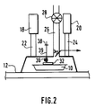
- Figure 2 is a schematic diagram showing the hood of figure 1 in the down position for testing.
- figure 1 shows a package 10 carried on conveyor 12.
- the package may be a tray having a stiff bottom and sides with a soft top or may be a soft bag.
- the conveyor may be solid or made of a mesh material.
- the conveyor is driven by motor 14 at one end of the conveyor.
- a hood 16 is mounted above the conveyor by means of cylinders 18 and 20 and pistons 22 and 24.
- the hood may be raised or lowered according to the action of the cylinders.
- the cylinders may be hydraulic or pneumatic cylinders or may be the electrical equivalent.
- a pipe 26 is connected to the hood for moving air therefrom.
- An aspiration turbine 28 causes air to move from within the hood and through the pipe.
- a helium sensor 30 is placed in the mouth of the pipe 26 and senses the air moving from the hood into the pipe.
- a tube then carries the air which is sensed to the gas detector 46 to determine if helium is present.
- the hood carries a plate 32 which is designed to press against the lid of the package during the testing operation.
- the surface of the plate may be flat, concave or convex depending on the shape of the package.
- the plate is carried by a rod 34 which extends through the top of the hood.
- a spring assembly 36 is mounted on the rod in order to force the plate toward the package.
- the rod carries a stop 38 which prevents the rod from falling from the hood when the package is not present. This stop may be adjusted to control the distance of the plate from the top of the hood.
- the spring 36 may be adjusted both as to height and stiffness in order to accommodate different size packages.
- the plate may be covered with rubber to cover sharp edges which could puncture the package.
- a package detector 40 determines when the package is below the hood in a testing position. When it reaches this position, a signal is sent to controller 42. The controller sends a signal to conveyor motor 14 to stop the movement of the conveyor. At the same time, a signal is sent to cylinder control 44 to actuate cylinders 18 and 20 and thereby the hood is lowered into position on the conveyor and over the package. When the hood is in position, the aspirator 28 removes the air within the hood. Sensor 30 determines if helium is present in the outflowing air. If helium is present, a signal is sent to gas detector 46. The detector then sends a signal to blade control 48 which actuates a blade (not shown) for removing the package from the conveyor.
- Figure 2 shows part of the apparatus described in figure 1. In this case, however, the hood is in the lowered position over the package.
- the pistons 22 and 24 are extended in order to lower the hood all the way to the conveyor 12.
- the plate 32 is in contact with the top of the package and applies a force thereto due to the compression of spring 36.
- the package 10 is sealed at a previous step after helium gas is introduced within the container.
- the amount of helium is preferably about 5 percent by volume although other percentages are possible.
- the package is then carried by conveyor 12 until it reaches a position under hood 16.
- the position detector 40 determines when the package is in the proper position and sends a signal to controller 42. Controller 42 stops the conveyor motor 14 to prevent the package from moving any further.
- a signal is sent to cylinder control 44 so that the cylinders are actuated to lower the hood over the package.
- the plate 32 comes into contact with the top of the package. This forces the rod 34 upwardly against the compression of spring 36. Since spring 36 resists this movement, pressure is brought to bear on the top of the package by plate 32.
- the aspiration turbine is turned on to create an ascending gas flow pattern inside the hood.
- helium sensor 30 determines whether helium is present in the removed gas. Since the plate 32 pushes against the package with a certain amount of force, the pressure inside the package is increased, thus causing any leak to be more prominent. If helium is detected, a signal is sent to gas detector 46 which then actuates the blade control to remove the package from the conveyor.
- the test is considered to be completed and the hood is then raised again.
- the conveyor is then started again and the package continues along the conveyor belt.
- a hood having a volume of 4.2 liters is connected to an aspirating blower having a flow rate of 16 standard liters per minute.
- the helium gas sensor is connected to a helium leak detector by way of a 45 centimeter flexible tube.
- Flexible bags made of a gas barrier polymeric material were used as sample packages for the test. The bags were filled with either carbon dioxide or nitrogen mixed with 5 percent helium gas. The total volume of the bags is between 250 and 450 cc. Before introducing the bags to the hood, the bags were perforated by a 0.5 mm diameter pin at various locations.
- the helium reference concentration in the hood varies between 2 and 3x10 ⁇ 8 atm cc/second.
- a nonperforated bag introduced into the hood is pressed by the plate.
- the detected level remains between 2 and 3x10 ⁇ 8 atm cc/second during the testing time of 30 seconds.
- the nonperforated bag is then replaced with a perforated bag.
- the gas level rises to 2-9x10 ⁇ 7 atm cc/second, 0.2 seconds after the plate has come into contact with the bag.
- the detected level decreases immediately and stabilizes to its initial value. Similar results occur with the perforation placed in different positions on the bag with the response time varying up to 0.6 seconds.
- the tracer gas can have a partial pressure 1 to 100%.
- a concentration of one percent to five percent volume of tracer gas is used according to the present invention.
- gases other than helium which are easily detectable, such as CO2, N2O, CH4, etc.
- the package may also include additional gas or gas mixtures which are used to preserve food products or other products contained therein.
- gases may be N2, CO2, CO, O2, N2O, Ar, etc. If a product contained in the package does not need a preserving gas, it may be desirable merely to have other kinds of gases for other purposes such as an inert gas merely to support the package.
Landscapes
- Physics & Mathematics (AREA)
- General Physics & Mathematics (AREA)
- Examining Or Testing Airtightness (AREA)
Claims (17)
- Verfahren zum Feststellen von undichten Stellen an einer Verpackung, welches die folgenden Schritte aufweist:- Bereitstellen eines detektierbarenSpürgases innerhalb einer Verpackung mit einem Partialdruck, der zwischen 1% und 100% liegt;- Abdichten (Versiegeln) der Verpackung;- Einführen der abgedichteten Verpackung in eine Haube;- Erzeugen einer kontinuierlichen Gasströmung in der Haube um die Verpackung herum, wobei das Gas der Gasströmung von dem Spürgas verschieden ist;- Ausüben von Druck auf die Oberfläche der Verpackung;- Prüfen der Gasströmung auf das Vorhandensein des Spürgases; und- Entscheiden, daß eine undichte Stelle vorliegt, wenn das Spürgas erfaßt wird.
- Verfahren nach Anspruch 1, welches als weiteren Schritt die Trennung von Verpackungen mit undichten Stellen von Verpackungen ohne undichte Stellen aufweist.
- Verfahren nach Anspruch 2, welches als weiteren Schritt die Bereitstellung einer gefederten Platte innerhalb der Haube zum Ausüben eines Druckes auf die Verpackung aufweist.
- Verfahren nach einem der Ansprüche 1 bis 3, wobei das Spürgas Helium ist.
- Verfahren nach einem der Ansprüche 1 bis 4, welches als weiteren Schritt die Bereitstellung von zumindest einem komplementären Gas innerhalb der Verpackung aufweist.
- Verfahren nach Anspruch 5, wobei das komplementäre Gas eines aus der N₂, CO₂, O₂, N₂O und Ar umfassenden Gruppe ist.
- Verfahren nach Anspruch 5 oder 6, wobei das komplementäre Gas verwendet wird, um ein Produkt innerhalb der Verpackung zu konservieren.
- Vorrichtung zum Erfassen einer undichten Stelle einer ein detektierbares Spürgas enthaltenden Schale oder Verpackung, wobei die Vorrichtung aufweist:- eine Haube mit einem größeren Volumen als die Schale oder Verpackung, um darin die Verpackung aufzunehmen;- eine Einrichtung zum Ausüben von Druck auf eine Oberfläche der Schale oder Verpackung, wobei die Einrichtung an der Haube montiert ist, und eine Platteneinrichtung zum Einschließen der Oberfläche umfaßt, welche mittels einer federnden Einrichtung, die zwischen der Haube und der Platteneinrichtung vorgespannt ist, federnd montiert ist und Druck auf die Schale oder Verpackung aufbringt, sowie eine Anschlageinrichtung umfaßt, welche die Bewegung der Platteneinrichtung in Richtung zur Schale oder Verpackung einstellbar begrenzt;- eine Ansaugvorrichtung zum Erzeugen eines Luftstroms innerhalb der Haube, um die Luft aus der Haube abzuziehen; und- einen Gassensor zum Bestimmen, wann das Spürgas in der abgezogenen Luft vorliegt.
- Vorrichtung nach Anspruch 8, wobei das Spürgas Helium ist.
- Vorrichtung nach Anspruch 8, wobei die Platte gefedert ist, um auf die Schale oder die Verpackung Druck auszuüben.
- Vorrichtung nach Anspruch 8, wobei die Platte einstellbar ist, damit sie für Schalen oder Verpackungen unterschiedlicher Größen passend ist.
- Vorrichtung nach Anspruch 9, wobei die Platte einstellbar ist, damit sie für unterschiedliche Verpackungs- oder Schalendicken passend ist.
- Vorrichtung nach Anspruch 8, wobei die Luft durch eine Ansaugvorrichtung innerhalb eines Auslaßrohres abgezogen wird und sich der Gassensor in dem Auslaßrohr in der Nähe der Haube befindet.
- Vorrichtung nach einem der Ansprüche 8 bis 13, welche weiterhin eine Fördereinrichtung aufweist, um die Verpackung oder die Schale unterhalb der Haube in Position zu bringen.
- Vorrichtung nach Anspruch 14, welche weiterhin aufweist:
eine auf den Gassensor ansprechende Einrichtung zur Bestimmung, daß eine Verpackung defekt ist; und
eine Einrichtung zum Entfernen der Verpackung von der Fördereinrichtung. - Vorrichtung nach Anspruch 15, welche weiterhin Einrichtungen zum Erfassen des Vorhandenseins der Verpackung unterhalb der Haube, zum Anhalten der Fördereinrichtung und zum Steuern zum Absenken der Haube aufweist.
- Vorrichtung nach Anspruch 16, welche weiterhin zumindest eine Kolben- und eine Zylindereinheit zum Absenken der Haube aufweist.
Applications Claiming Priority (4)
| Application Number | Priority Date | Filing Date | Title |
|---|---|---|---|
| US48687090A | 1990-03-01 | 1990-03-01 | |
| US486870 | 1990-03-01 | ||
| US07/581,191 US5029463A (en) | 1990-03-01 | 1990-09-11 | Leak detection device for in-line measurement of package integrity |
| US581191 | 1990-09-11 |
Publications (3)
| Publication Number | Publication Date |
|---|---|
| EP0445002A2 EP0445002A2 (de) | 1991-09-04 |
| EP0445002A3 EP0445002A3 (en) | 1992-07-29 |
| EP0445002B1 true EP0445002B1 (de) | 1995-06-28 |
Family
ID=27048828
Family Applications (1)
| Application Number | Title | Priority Date | Filing Date |
|---|---|---|---|
| EP91400465A Expired - Lifetime EP0445002B1 (de) | 1990-03-01 | 1991-02-21 | Leckermittlungsvorrichtung zur on-line-Messung der Dichtigkeit einer Verpackung |
Country Status (7)
| Country | Link |
|---|---|
| US (1) | US5029463A (de) |
| EP (1) | EP0445002B1 (de) |
| JP (1) | JPH04216430A (de) |
| CA (1) | CA2037185A1 (de) |
| DE (1) | DE69110706T2 (de) |
| DK (1) | DK0445002T3 (de) |
| ES (1) | ES2074239T3 (de) |
Families Citing this family (45)
| Publication number | Priority date | Publication date | Assignee | Title |
|---|---|---|---|---|
| US5497654A (en) * | 1989-01-27 | 1996-03-12 | Lehmann; Martin | Method and apparatus for leak testing a container |
| US5345814A (en) * | 1990-12-28 | 1994-09-13 | Whirlpool Corporation | Method and apparatus for testing vacuum insulation panel quality |
| DE9202350U1 (de) * | 1992-02-24 | 1992-04-16 | Leybold AG, 6450 Hanau | In Flüssigkeiten einsetzbare Gassonde |
| US5309752A (en) * | 1992-07-17 | 1994-05-10 | Praxair Technology, Inc. | Leakage measurement into a gas-charged collapsible container |
| ES2220910T3 (es) * | 1992-11-24 | 2004-12-16 | Commonwealth Scientific And Industrial Research Organisation | Eliminadores de oxieno independientes de catalizadores de metales. |
| FR2703782B1 (fr) * | 1993-04-08 | 1995-05-12 | Cit Alcatel | Installation de détection de fuites pour le contrôle d'étanchéité d'emballages scellés. |
| US5499529A (en) * | 1993-06-02 | 1996-03-19 | The United States Of America As Represented By The United States Department Of Energy | Detecting small holes in packages |
| JP3105390B2 (ja) * | 1994-04-04 | 2000-10-30 | グンゼ株式会社 | ピンホール検査装置 |
| FR2732455B1 (fr) * | 1995-03-31 | 1997-06-13 | Davey Bickford | Initiateur electropyrotechnique, procede de realisation d'un tel initiateur et systeme de securite pour vehicule |
| FI970665A0 (fi) | 1996-04-15 | 1997-02-17 | Espoon Paineilma Oy | Foerfarande foer identifiering av laeckage i en foerpackning isynnerhet livsmedels- och laekemedelsfoerpackning samt foerbaettrande av haollbarheten hos vaetskeformiga livsmedel vilka aer foerpackade i aseptiska kartongfoerpackningar |
| WO1998025120A1 (en) * | 1996-12-02 | 1998-06-11 | True Technology, Inc. | Method and apparatus for detecting leaks |
| DK1320738T3 (da) * | 2000-09-26 | 2009-06-15 | Martin Lehmann | Fremgangsmåde og apparat til tæthedsprövning af lukkede beholdere |
| EP1324014A4 (de) * | 2000-10-02 | 2007-06-27 | Takachiho Seiki Co Ltd | Leckerkennungseinrichtung für hermetische gehäuse |
| DE10102820A1 (de) * | 2001-01-23 | 2002-07-25 | Iwk Verpackungstechnik Gmbh | Verfahren zur Herstellung einer Blisterverpackung und Blisterverpackungsmaschine |
| US6513366B1 (en) | 2001-10-11 | 2003-02-04 | Packaging Technologies & Inspection Llc | Method and apparatus for package leak testing |
| EP1836467B1 (de) | 2005-01-10 | 2012-04-25 | Mocon, Inc. | Instrument und verfahren zum erkennen von lecks in hermetisch abgedichteten kapselungen |
| CN101160518B (zh) | 2005-02-02 | 2010-08-04 | 膜康公司 | 探测和报告气密包装中泄漏大小的仪器和方法 |
| WO2006088542A2 (en) | 2005-02-14 | 2006-08-24 | Mocon, Inc. | Detecting and reporting the location of a leak in hermetically sealed packaging |
| US20070062236A1 (en) * | 2005-09-16 | 2007-03-22 | Heavens Glenn G | Cracked barrel detection system |
| JP2007108101A (ja) * | 2005-10-17 | 2007-04-26 | Takachiho Seiki Kk | 密封体の漏れ検査装置 |
| JP4475224B2 (ja) * | 2005-11-15 | 2010-06-09 | 株式会社デンソー | 気密漏れ検査装置 |
| EP1980833A1 (de) * | 2007-04-04 | 2008-10-15 | V-Tec Metaalbewerking B.V. | Lecküberprüfungsvorrichtung |
| DE102007046654B4 (de) * | 2007-09-28 | 2012-01-26 | Evonik Carbon Black Gmbh | Vorrichtung und Verfahren zur Bestimmung der Dichtheit von befüllten Verpackungen |
| ES2665764T3 (es) * | 2009-11-20 | 2018-04-27 | Packaging Technologies & Inspection Llc | Estado de vacío en reposo para procedimiento y sistema de prueba de estanqueidad mediante medida de disminución del vacío |
| EP2686657B1 (de) * | 2011-03-16 | 2019-11-27 | Norden Machinery Ab | Verfahren und anordnung zur erkennung von leckagen |
| GB2493009A (en) * | 2011-07-21 | 2013-01-23 | Packtester Ltd | Seal integrity detector for sealed packages |
| ITMI20120791A1 (it) * | 2012-05-09 | 2013-11-10 | Rivoira S P A | Nuove miscele di gas per il confezionamento in atmosfera protettiva (map) di prodotti alimentari idonee per controlli di tenuta non distruttivi delle confezioni |
| US8582105B1 (en) * | 2012-06-14 | 2013-11-12 | Intermolecular, Inc. | Method and apparatus for leak detection in H2Se furnace |
| DE102013000086A1 (de) | 2013-01-08 | 2014-07-10 | Winfried Ridzewski | Dichtigkeitsprüfvorrichtung und Verfahren zur Ausführung mit einer solchen |
| WO2014116838A1 (en) * | 2013-01-24 | 2014-07-31 | PBM Nutritionals, LLC | Apparatus and method for making canister and for detecting leaks for quality assurance |
| US9274023B2 (en) | 2013-03-13 | 2016-03-01 | Teledyne Instruments, Inc. | Flexible lid seal integrity sensor |
| WO2015140797A2 (en) | 2014-03-20 | 2015-09-24 | D.I.R. Technologies (Detection Ir) Ltd. | Method and system for determining package integrity |
| DK178977B1 (en) * | 2015-12-07 | 2017-07-24 | Dansensor As | Fremgangsmåde og indretning til at teste en forseglet emballage for lækkende sporgas |
| AU2017268056B2 (en) * | 2016-05-18 | 2021-08-05 | Lineriders Inc. | Apparatus and methodologies for leak detection using gas and infrared thermography |
| EP3583405B1 (de) | 2017-02-20 | 2026-02-18 | Yoran Imaging Ltd. | Verfahren und system zur bestimmung der paketintegrität |
| US11836908B2 (en) | 2017-02-20 | 2023-12-05 | Yoran Imaging Ltd. | Method and system for determining package integrity |
| US12430745B2 (en) | 2017-02-20 | 2025-09-30 | Yoran Imaging Ltd. | Method and system for determining package integrity |
| CN109703836A (zh) * | 2017-10-26 | 2019-05-03 | 庆富机械有限公司 | 测漏装置及具有测漏装置的密封包装设备及其使用方法 |
| WO2019162933A1 (en) | 2018-02-21 | 2019-08-29 | Yoran Imaging Ltd. | Methods and systems for thermal imaging of moving objects |
| CN109013382A (zh) * | 2018-06-28 | 2018-12-18 | 关岭自治县断桥绿华农产品农民专业合作社 | 一种食品包装真空度检测装置 |
| IT201900006920A1 (it) * | 2019-05-16 | 2020-11-16 | Ft System Srl | Metodo ed apparato per il riconoscimento della presenza di fughe da contenitori sigillati |
| JP6927257B2 (ja) * | 2019-08-29 | 2021-08-25 | 椿本メイフラン株式会社 | 搬送装置 |
| FR3100888B1 (fr) | 2019-09-17 | 2021-11-26 | Air Liquide | Procédé et équipement de détection d’un défaut d’étanchéité d’un emballage |
| US11774315B2 (en) | 2020-08-21 | 2023-10-03 | Teledyne Instruments, Inc. | Flexible lid seal integrity sensor |
| CN113611925B (zh) * | 2021-08-27 | 2022-12-27 | 广东嘉尚新能源科技有限公司 | 一种用于软包锂电芯的自动定距离输送密封性检测装置 |
Family Cites Families (9)
| Publication number | Priority date | Publication date | Assignee | Title |
|---|---|---|---|---|
| US3091114A (en) * | 1959-12-17 | 1963-05-28 | Air Reduction | Method and apparatus for testing sealed packages for leaks |
| US3027753A (en) * | 1960-04-29 | 1962-04-03 | Gen Electric | Leak detection device |
| US3591944A (en) * | 1969-03-03 | 1971-07-13 | Safeway Stores | Method and apparatus for detection of leaks in seals of packages |
| US3744210A (en) * | 1971-06-28 | 1973-07-10 | Standard Packaging Corp | Packaging machine and method |
| US3837228A (en) * | 1973-04-09 | 1974-09-24 | Vacuum Inst Corp | Tracer gas-permeable probe for leak detectors |
| US3888111A (en) * | 1973-11-21 | 1975-06-10 | Gen Motors Corp | Sealed beam headlamp unit leak detection system |
| US4158960A (en) * | 1978-05-04 | 1979-06-26 | The United States Of America As Represented By The Secretary Of The Army | Microcircuit fine leak test apparatus |
| EP0165342A1 (de) * | 1984-05-23 | 1985-12-27 | VARIAN S.p.A. | Vorrichtung zur Feststellung von Lecks in unterDruck gesetzten Objekten und Containern |
| JPH0737912B2 (ja) * | 1987-09-22 | 1995-04-26 | 食品産業オンラインセンサー技術研究組合 | 窒素ガス充填包装体におけるリークの検査方法 |
-
1990
- 1990-09-11 US US07/581,191 patent/US5029463A/en not_active Expired - Fee Related
-
1991
- 1991-02-21 DK DK91400465.0T patent/DK0445002T3/da active
- 1991-02-21 ES ES91400465T patent/ES2074239T3/es not_active Expired - Lifetime
- 1991-02-21 EP EP91400465A patent/EP0445002B1/de not_active Expired - Lifetime
- 1991-02-21 DE DE69110706T patent/DE69110706T2/de not_active Expired - Fee Related
- 1991-02-26 JP JP3030989A patent/JPH04216430A/ja active Pending
- 1991-02-27 CA CA002037185A patent/CA2037185A1/en not_active Abandoned
Also Published As
| Publication number | Publication date |
|---|---|
| ES2074239T3 (es) | 1995-09-01 |
| CA2037185A1 (en) | 1991-09-02 |
| US5029463A (en) | 1991-07-09 |
| EP0445002A3 (en) | 1992-07-29 |
| DE69110706T2 (de) | 1995-11-23 |
| EP0445002A2 (de) | 1991-09-04 |
| JPH04216430A (ja) | 1992-08-06 |
| DE69110706D1 (de) | 1995-08-03 |
| DK0445002T3 (da) | 1995-08-28 |
Similar Documents
| Publication | Publication Date | Title |
|---|---|---|
| US5029463A (en) | Leak detection device for in-line measurement of package integrity | |
| US5111684A (en) | Method and apparatus for leak testing packages | |
| JP5840237B2 (ja) | 漏れ検出方法および装置 | |
| AU2005252715B2 (en) | An apparatus and method for testing flexible packages for defects | |
| JP4410854B2 (ja) | 包装材のシール性の検査 | |
| US6279384B1 (en) | Method for treating a product and a leak-detection device | |
| CN101201289B (zh) | 在线检测瓶子封口气密性的装置 | |
| US11105704B2 (en) | Method and apparatus for an integrity test of a flexible container with inspection fluid | |
| EP3698116B1 (de) | System und verfahren zur bestimmung der integrität von behältern durch optische messung | |
| JP7626715B2 (ja) | 密封容器からの漏れを検出する方法および装置 | |
| JPS60227144A (ja) | 漏れ検査方法および装置 | |
| US4922746A (en) | Leak testing | |
| ES2101226T3 (es) | Deteccion de fugas en envases. | |
| JP7582973B2 (ja) | 密封容器からの漏れの存在を認識する方法および装置 | |
| US3805595A (en) | Apparatus for testing leakage | |
| JPH07187152A (ja) | 密封袋のリークテスト方法 | |
| US4539836A (en) | Package leak tester | |
| JP2006329650A (ja) | 包装リーク検査装置 | |
| US20240077394A1 (en) | Apparatus, plant and method for inspecting flexible packages | |
| JP7269687B1 (ja) | 包装体の密封不良検査方法およびそれに用いる検査装置 | |
| JP2000111443A (ja) | 容器の漏洩検査方法及びその装置 | |
| US20250290822A1 (en) | Method and device for leak detection | |
| JPH0872831A (ja) | 真空包装品のシール不良検査方法 |
Legal Events
| Date | Code | Title | Description |
|---|---|---|---|
| PUAI | Public reference made under article 153(3) epc to a published international application that has entered the european phase |
Free format text: ORIGINAL CODE: 0009012 |
|
| 17P | Request for examination filed |
Effective date: 19910225 |
|
| AK | Designated contracting states |
Kind code of ref document: A2 Designated state(s): BE DE DK ES FR IT |
|
| PUAL | Search report despatched |
Free format text: ORIGINAL CODE: 0009013 |
|
| AK | Designated contracting states |
Kind code of ref document: A3 Designated state(s): BE DE DK ES FR IT |
|
| 17Q | First examination report despatched |
Effective date: 19940120 |
|
| GRAA | (expected) grant |
Free format text: ORIGINAL CODE: 0009210 |
|
| AK | Designated contracting states |
Kind code of ref document: B1 Designated state(s): BE DE DK ES FR IT |
|
| ITF | It: translation for a ep patent filed | ||
| REF | Corresponds to: |
Ref document number: 69110706 Country of ref document: DE Date of ref document: 19950803 |
|
| ET | Fr: translation filed | ||
| REG | Reference to a national code |
Ref country code: DK Ref legal event code: T3 |
|
| REG | Reference to a national code |
Ref country code: ES Ref legal event code: FG2A Ref document number: 2074239 Country of ref document: ES Kind code of ref document: T3 |
|
| PLBI | Opposition filed |
Free format text: ORIGINAL CODE: 0009260 |
|
| PLBQ | Unpublished change to opponent data |
Free format text: ORIGINAL CODE: EPIDOS OPPO |
|
| PLBF | Reply of patent proprietor to notice(s) of opposition |
Free format text: ORIGINAL CODE: EPIDOS OBSO |
|
| 26 | Opposition filed |
Opponent name: LEYBOLD VAKUUM GMBH Effective date: 19960326 |
|
| PLBF | Reply of patent proprietor to notice(s) of opposition |
Free format text: ORIGINAL CODE: EPIDOS OBSO |
|
| PLBO | Opposition rejected |
Free format text: ORIGINAL CODE: EPIDOS REJO |
|
| PLBN | Opposition rejected |
Free format text: ORIGINAL CODE: 0009273 |
|
| STAA | Information on the status of an ep patent application or granted ep patent |
Free format text: STATUS: OPPOSITION REJECTED |
|
| 27O | Opposition rejected |
Effective date: 19970424 |
|
| PGFP | Annual fee paid to national office [announced via postgrant information from national office to epo] |
Ref country code: FR Payment date: 20020114 Year of fee payment: 12 |
|
| PGFP | Annual fee paid to national office [announced via postgrant information from national office to epo] |
Ref country code: DK Payment date: 20020115 Year of fee payment: 12 |
|
| PGFP | Annual fee paid to national office [announced via postgrant information from national office to epo] |
Ref country code: DE Payment date: 20020121 Year of fee payment: 12 |
|
| PGFP | Annual fee paid to national office [announced via postgrant information from national office to epo] |
Ref country code: ES Payment date: 20020205 Year of fee payment: 12 |
|
| PGFP | Annual fee paid to national office [announced via postgrant information from national office to epo] |
Ref country code: BE Payment date: 20020213 Year of fee payment: 12 |
|
| PG25 | Lapsed in a contracting state [announced via postgrant information from national office to epo] |
Ref country code: ES Free format text: LAPSE BECAUSE OF NON-PAYMENT OF DUE FEES Effective date: 20030222 |
|
| PG25 | Lapsed in a contracting state [announced via postgrant information from national office to epo] |
Ref country code: DK Free format text: LAPSE BECAUSE OF NON-PAYMENT OF DUE FEES Effective date: 20030228 Ref country code: BE Free format text: LAPSE BECAUSE OF NON-PAYMENT OF DUE FEES Effective date: 20030228 |
|
| PG25 | Lapsed in a contracting state [announced via postgrant information from national office to epo] |
Ref country code: DE Free format text: LAPSE BECAUSE OF NON-PAYMENT OF DUE FEES Effective date: 20030902 |
|
| PG25 | Lapsed in a contracting state [announced via postgrant information from national office to epo] |
Ref country code: FR Free format text: LAPSE BECAUSE OF NON-PAYMENT OF DUE FEES Effective date: 20031031 |
|
| REG | Reference to a national code |
Ref country code: DK Ref legal event code: EBP |
|
| REG | Reference to a national code |
Ref country code: FR Ref legal event code: ST |
|
| REG | Reference to a national code |
Ref country code: ES Ref legal event code: FD2A Effective date: 20030222 |
|
| PG25 | Lapsed in a contracting state [announced via postgrant information from national office to epo] |
Ref country code: IT Free format text: LAPSE BECAUSE OF NON-PAYMENT OF DUE FEES Effective date: 20050221 |