EP0445006B1 - Wärmetauscher mit kreisförmiger Strömung - Google Patents
Wärmetauscher mit kreisförmiger Strömung Download PDFInfo
- Publication number
- EP0445006B1 EP0445006B1 EP19910400482 EP91400482A EP0445006B1 EP 0445006 B1 EP0445006 B1 EP 0445006B1 EP 19910400482 EP19910400482 EP 19910400482 EP 91400482 A EP91400482 A EP 91400482A EP 0445006 B1 EP0445006 B1 EP 0445006B1
- Authority
- EP
- European Patent Office
- Prior art keywords
- channels
- energy exchange
- plate
- oil
- plates
- Prior art date
- Legal status (The legal status is an assumption and is not a legal conclusion. Google has not performed a legal analysis and makes no representation as to the accuracy of the status listed.)
- Expired - Lifetime
Links
- 239000012530 fluid Substances 0.000 claims description 23
- 238000004519 manufacturing process Methods 0.000 claims description 7
- 238000000034 method Methods 0.000 claims description 4
- 239000003921 oil Substances 0.000 description 83
- 238000001816 cooling Methods 0.000 description 20
- 239000002826 coolant Substances 0.000 description 19
- 239000000463 material Substances 0.000 description 9
- 239000010705 motor oil Substances 0.000 description 5
- 230000006835 compression Effects 0.000 description 4
- 238000007906 compression Methods 0.000 description 4
- 238000000926 separation method Methods 0.000 description 4
- 239000000919 ceramic Substances 0.000 description 3
- 239000012809 cooling fluid Substances 0.000 description 3
- 229910052751 metal Inorganic materials 0.000 description 3
- 239000002184 metal Substances 0.000 description 3
- 239000004033 plastic Substances 0.000 description 3
- 229920003023 plastic Polymers 0.000 description 3
- 238000007789 sealing Methods 0.000 description 3
- 229910001369 Brass Inorganic materials 0.000 description 2
- RYGMFSIKBFXOCR-UHFFFAOYSA-N Copper Chemical compound [Cu] RYGMFSIKBFXOCR-UHFFFAOYSA-N 0.000 description 2
- 229910000831 Steel Inorganic materials 0.000 description 2
- 229910052782 aluminium Inorganic materials 0.000 description 2
- XAGFODPZIPBFFR-UHFFFAOYSA-N aluminium Chemical compound [Al] XAGFODPZIPBFFR-UHFFFAOYSA-N 0.000 description 2
- 230000000712 assembly Effects 0.000 description 2
- 238000000429 assembly Methods 0.000 description 2
- 239000010951 brass Substances 0.000 description 2
- 229910052802 copper Inorganic materials 0.000 description 2
- 239000010949 copper Substances 0.000 description 2
- 230000000694 effects Effects 0.000 description 2
- 150000002739 metals Chemical class 0.000 description 2
- 238000000465 moulding Methods 0.000 description 2
- 239000003507 refrigerant Substances 0.000 description 2
- 239000010935 stainless steel Substances 0.000 description 2
- 229910001220 stainless steel Inorganic materials 0.000 description 2
- 239000010959 steel Substances 0.000 description 2
- XLYOFNOQVPJJNP-UHFFFAOYSA-N water Substances O XLYOFNOQVPJJNP-UHFFFAOYSA-N 0.000 description 2
- 238000003466 welding Methods 0.000 description 2
- 239000000853 adhesive Substances 0.000 description 1
- 230000001070 adhesive effect Effects 0.000 description 1
- 229910045601 alloy Inorganic materials 0.000 description 1
- 239000000956 alloy Substances 0.000 description 1
- 230000002528 anti-freeze Effects 0.000 description 1
- 230000005540 biological transmission Effects 0.000 description 1
- 239000004566 building material Substances 0.000 description 1
- 239000010724 circulating oil Substances 0.000 description 1
- 238000002485 combustion reaction Methods 0.000 description 1
- 239000000112 cooling gas Substances 0.000 description 1
- 238000005260 corrosion Methods 0.000 description 1
- 230000007797 corrosion Effects 0.000 description 1
- 230000003247 decreasing effect Effects 0.000 description 1
- 238000010586 diagram Methods 0.000 description 1
- 238000005516 engineering process Methods 0.000 description 1
- 239000007788 liquid Substances 0.000 description 1
- 238000005461 lubrication Methods 0.000 description 1
- 239000000203 mixture Substances 0.000 description 1
- 230000008520 organization Effects 0.000 description 1
- 230000002085 persistent effect Effects 0.000 description 1
- 239000002861 polymer material Substances 0.000 description 1
- 239000002904 solvent Substances 0.000 description 1
- 239000010729 system oil Substances 0.000 description 1
- 238000002604 ultrasonography Methods 0.000 description 1
Images


Classifications
-
- F—MECHANICAL ENGINEERING; LIGHTING; HEATING; WEAPONS; BLASTING
- F28—HEAT EXCHANGE IN GENERAL
- F28D—HEAT-EXCHANGE APPARATUS, NOT PROVIDED FOR IN ANOTHER SUBCLASS, IN WHICH THE HEAT-EXCHANGE MEDIA DO NOT COME INTO DIRECT CONTACT
- F28D9/00—Heat-exchange apparatus having stationary plate-like or laminated conduit assemblies for both heat-exchange media, the media being in contact with different sides of a conduit wall
- F28D9/0031—Heat-exchange apparatus having stationary plate-like or laminated conduit assemblies for both heat-exchange media, the media being in contact with different sides of a conduit wall the conduits for one heat-exchange medium being formed by paired plates touching each other
- F28D9/0043—Heat-exchange apparatus having stationary plate-like or laminated conduit assemblies for both heat-exchange media, the media being in contact with different sides of a conduit wall the conduits for one heat-exchange medium being formed by paired plates touching each other the plates having openings therein for circulation of at least one heat-exchange medium from one conduit to another
- F28D9/0056—Heat-exchange apparatus having stationary plate-like or laminated conduit assemblies for both heat-exchange media, the media being in contact with different sides of a conduit wall the conduits for one heat-exchange medium being formed by paired plates touching each other the plates having openings therein for circulation of at least one heat-exchange medium from one conduit to another with U-flow or serpentine-flow inside conduits; with centrally arranged openings on the plates
-
- F—MECHANICAL ENGINEERING; LIGHTING; HEATING; WEAPONS; BLASTING
- F28—HEAT EXCHANGE IN GENERAL
- F28D—HEAT-EXCHANGE APPARATUS, NOT PROVIDED FOR IN ANOTHER SUBCLASS, IN WHICH THE HEAT-EXCHANGE MEDIA DO NOT COME INTO DIRECT CONTACT
- F28D9/00—Heat-exchange apparatus having stationary plate-like or laminated conduit assemblies for both heat-exchange media, the media being in contact with different sides of a conduit wall
- F28D9/0012—Heat-exchange apparatus having stationary plate-like or laminated conduit assemblies for both heat-exchange media, the media being in contact with different sides of a conduit wall the apparatus having an annular form
-
- F—MECHANICAL ENGINEERING; LIGHTING; HEATING; WEAPONS; BLASTING
- F28—HEAT EXCHANGE IN GENERAL
- F28D—HEAT-EXCHANGE APPARATUS, NOT PROVIDED FOR IN ANOTHER SUBCLASS, IN WHICH THE HEAT-EXCHANGE MEDIA DO NOT COME INTO DIRECT CONTACT
- F28D9/00—Heat-exchange apparatus having stationary plate-like or laminated conduit assemblies for both heat-exchange media, the media being in contact with different sides of a conduit wall
- F28D9/0031—Heat-exchange apparatus having stationary plate-like or laminated conduit assemblies for both heat-exchange media, the media being in contact with different sides of a conduit wall the conduits for one heat-exchange medium being formed by paired plates touching each other
-
- F—MECHANICAL ENGINEERING; LIGHTING; HEATING; WEAPONS; BLASTING
- F28—HEAT EXCHANGE IN GENERAL
- F28D—HEAT-EXCHANGE APPARATUS, NOT PROVIDED FOR IN ANOTHER SUBCLASS, IN WHICH THE HEAT-EXCHANGE MEDIA DO NOT COME INTO DIRECT CONTACT
- F28D9/00—Heat-exchange apparatus having stationary plate-like or laminated conduit assemblies for both heat-exchange media, the media being in contact with different sides of a conduit wall
- F28D9/0031—Heat-exchange apparatus having stationary plate-like or laminated conduit assemblies for both heat-exchange media, the media being in contact with different sides of a conduit wall the conduits for one heat-exchange medium being formed by paired plates touching each other
- F28D9/0043—Heat-exchange apparatus having stationary plate-like or laminated conduit assemblies for both heat-exchange media, the media being in contact with different sides of a conduit wall the conduits for one heat-exchange medium being formed by paired plates touching each other the plates having openings therein for circulation of at least one heat-exchange medium from one conduit to another
Definitions
- the subject of this invention is an energy exchange structure according to the preamble of claim 1 and an automobile oil cooler comprising such a structure, the invention being particularly suitable for applications in oil cooling equipment of automobile engines in which high ratios - heat transfer / oil pressure drop - are desired.
- the invention also relates to a method of manufacturing such an oil cooler.
- heat transfer systems external to the engine block, usually used as oil coolers in automotive applications included a continuous serpentine tube, with or without cooling fins, installed outside the engine, usually in the air stream in front of the radiator or in the latter's cooling radiator.
- Oil such as engine oil, transmission oil or any other fluid, is sent into the tube to be cooled.
- a refrigerant passed over the tube, for example in a radiator using a refrigerant or in a separate element using air cooling, thus ensuring the exchange of energy in the tube between the hot oil and the coolant.
- the oil coolers were subsequently mounted on the engine, usually between the engine block and the oil filter. mounted externally to the engine; they cooled the oil coming in or leaving the filter using the fluid from the engine cooling system.
- These oil filter mounted coolers generally included multiple hollow plate structures spaced apart from each other and generally parallel between which the oil and coolant flow in parallel planes to maximize heat transfer .
- Such spaced plate structures can be fitted with cooling fins between the hollow structures or are constructed of corrugated plates. In such devices, oil flows from an orifice located on or near the filter to the cooler and flows between the parallel plates of the cooler.
- the cooling agent coming from the engine cooling system circulates between and / or near the parallel plates containing the circulating oil, thereby transferring the heat energy from the oil to the cooling agent.
- the cooling agent coming from the engine cooling system circulates between and / or near the parallel plates containing the circulating oil, thereby transferring the heat energy from the oil to the cooling agent.
- One of the typical characteristics of oil coolers mounted on the filter is that one or both fluids circulate in a generally circular direction relative to the center of the cooler and, generally, the heat transfer elements of the fins and wavy surfaces, are generally not aligned in more than one or two directions.
- One of the aims of this invention is to provide energy exchange structures having better heat transfer.
- Another object of this invention is to provide energy exchange structures causing only a reduced drop in the internal pressure of the fluid.
- Another object of the invention is to provide an automotive oil cooler with reduced internal oil pressure drop.
- Yet another object of the invention is to propose a method of manufacturing energy exchange structures ensuring efficient heat transfer associated with a drop in internal pressure of the reduced fluid.
- the invention relates to an energy exchange structure, comprising plates generally opposite in parallel and assembled to define between them a hollow passage in which a fluid circulates in a generally circular direction between an inlet and an outlet, the said opposite plates being corrugated to form a cruciform structure defining multiple opposing gutters projecting into the hollow passage and arranged to constitute four or more sets of generally parallel gutters drawn to make an oblique with respect to the adjacent sets and also with respect to the direction of circulation of the fluid which flows in the hollow passage formed by the plates assembled to one another.
- the sets of gutters of a first plate being arranged to join in cross with the opposite sets of gutters of a second plate so that the volume comprised between the opposed gutters of the opposite sets defines cruciform passages in which the fluid can circulate.
- Automobile engine oil coolers include multiple opposing plates, stacked to form interconnected energy exchange structures for flow of oil in a generally circular direction.
- the inputs of the energy exchange structures open into an input collector where they are connected in parallel with the other inputs or else they are connected in series with the inputs and outputs of a second structure.
- the outputs lead to an output collector and are also connected either in parallel or in series with the inputs and outputs of a second structure.
- the stacked and interconnected energy exchange structures provide the passage for the flow of oil inside the energy exchange structures and for the circulation of a cooling fluid outside the energy structures. energy exchange.
- the preferential direction of the flow of the fluid generally forms an oblique with respect to the axis of the opposite gutters of the opposite plates of the energy exchange structures to improve the energy exchange.
- the energy exchange structures can be installed inside a container acting as a housing in which the liquid and / or the cooling gas can be circulated above and between the opposing plates, or alternatively may be exposed to be subjected to a draft or other coolant.
- the periphery of the stacked energy exchange structures can be made integral with the wall of the housing so as to define separate passages for the coolant which can also be connected separately or interconnected in parallel or in series with the inlet collectors and / or coolant outlet.
- Automobile engine oil coolers are manufactured by a process in which opposing plates are corrugated to obtain a cruciform structure forming multiple gutters arranged in four or more sets of generally parallel gutters, with each set forming an oblique with the direction of the adjacent assemblies as well as with the circular direction of the flow of the fluid in the hollow passage formed between the attached plates.
- the gutters of a first plate are in contact with the tops of the gutters in opposition to a second plate and the area between the gutters in opposition constitutes a passage which preferably must form an oblique between 5 and 75 ° with respect to the circular direction of flow in energy exchange structures.
- Said first and second plates are assembled to form a hollow passage, comprising an inlet and an outlet for the fluid, the passage being constructed to direct the incoming fluid from the inlet towards the outlet in a generally circular direction.
- the multiple energy exchange structures can be assembled in series and / or in parallel to constitute the cooler, with an input of a first energy exchange structure connected to an output or to an input of a second energy exchange structure.
- the energy exchange structures thus assembled are placed in a container serving as a housing equipped with an inlet and an outlet for the coolant.
- the contiguous outer edges of the opposing plates are extended to form a flat plate providing additional cooling surface on the outer edges of the exchange structures.
- Such an extension allows the circulation of the cooling fluid over the outer limits of the stacked structures for additional cooling and may also present a practical means of assembling the structures together to immobilize them in the housing.
- Figure 1 is a top perspective view of an oil cooler with an energy exchange structure designed according to the present invention.
- Figure 2 is a bottom perspective view of the oil cooler of Figure 1.
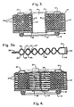
- Figure 3 is a sectional view taken approximately along line 3-3 of Figure 1.
- Figure 3a is an enlarged sectional view of a hollow energy exchange structure of Figure 3.
- Figure 4 is a sectional view taken approximately along line 4-4 of Figure 1.
- Figure 5 is a perspective view of an energy exchange structure designed according to the present invention.
- Figure 6 is a plan view of the interior surface of the top plate of Figure 5.
- Figure 7 is a plan view of the interior surface of the bottom plate of Figure 5.
- Figure 8 is a schematic view of another embodiment of the invention.
- the cooler 10 comprises a metal housing 11 having a base for attachment to the engine 12, a base for attachment to the oil filter 20, an outer wall for the housing 17 and an interior opening for the housing 14.
- the base for attachment to the engine 12 includes an oil inlet 13 and an engine sealing groove 16 which maintains the oil seal 15, as shown in Figures 3 and 4.
- the outer wall 17 of the housing 11 includes the inlet of the coolant 18 and the outlet of the coolant 19.
- the bottom of attachment to the oil filter 20 includes an oil outlet 21 and a sealing surface to the oil filter 22.
- the interior opening of the housing 14 goes from the bottom of the attachment to the engine 12 to the bottom of the attachment to the oil filter 20 and thus presents a passage in which a removable oil filter can be fixed to the engine while ensuring the sealing of the filter and the cooler to the engine as well as the return passage of the cooled and filtered oil to the engine.
- the oil cooler 10 comprises a set of hollow energy exchange structures, contained in the housing 11, through which the oil circulates between the oil inlet 13 and the oil outlet 21. Surrounding at at least part of the energy exchange structures, there are hollow passages in which the coolant can flow from the inlet of the coolant 18 to the outlet of the coolant 19 while establishing an exchange ratio of energy with hollow energy exchange structures.
- a first fluid first brought to high temperature, such as hot engine oil, enters the oil cooler 10 through the oil inlet 13, circulates between the opposite plates by the generally circular passages of all of the hollow energy exchange structures up to the engine oil outlet from the cooler 21 to the inlet of the oil filter (not shown in the figures).
- the cooled oil passes through the oil filter, then is directed to a hollow oil filter attachment rod (not shown in the figures) which extends to the engine passing through the interior opening 14 of the housing.
- the hollow oil filter attachment rod attaches to the engine and is threaded in a conventional manner to compress the oil filter and oil cooler to the engine. The rod therefore provides both a means of fixing the filter and the cooler to the engine and a return passage of the cooled and filtered oil from the filter to the engine.
- the oil can follow an opposite path: from the engine to the filter by the hollow rod, then to the cooler and back to the engine from the cooler.
- the circulation of oil through the exchange structures is directed by several assemblies, arranged to form an angle between them, of generally parallel gutters which protrude into the hollow passage of the opposite plates.
- the oil flow is passively separated and mixed by the cruciform paths formed by the opposing gutters thus increasing the contact of the oil flow with the opposite plates of the energy exchange structure.
- the heat energy from the oil is dissipated in the opposite plates of the energy exchange structures and in all the fins with which it can be in contact.
- a second fluid such as a coolant such as a conventional water / antifreeze mixture, enters through the inlet of the cooler 18 so as to circulate through opposite plates or any fin with which it can be in contact, preferably in the direction contrary to the direction of flow of the oil flow.
- the heat energy is dissipated by the energy exchange structures when the heat energy of the cooling fluid is less than the heat energy of the exchange structures.
- the coolant flows into the housing containing the exchange structures towards the outlet of the cooler 19 to be recycled by the cooling system.
- FIG 3 illustrates a sectional view of the oil cooler of Figure 1 taken approximately along line 3-3, in which there is seen a stack of hollow energy exchange structures 23 to the interior of the housing 11.
- an energy exchange structure is shown enlarged to show an upper corrugated opposite plate 24 and a lower opposite plate 25, joined to form a welded outer border 26.
- the low points 27 of the gutters directed towards the inside of the upper opposite plate 24 cross the low points 28 of the gutters directed towards the inside of the opposite opposite plate 25, with the area between the low points of the gutters of a plate comprising ridges 29 in the upper plate 24 and ridges 30 in the lower plate 25.
- the gutters formed downward direct the flow of oil in the exchange structures along the line of the ridges , the cruciform gutters continuously performing passive separation, mixing and redirecting in oblique angular directions the flow of oil in a generally circumferential direction from the entry of the energy exchange structure to the exit of this structure.
- the volumes between the energy exchange structures stacked one on the other also constitute passages formed by the undulations of the plates.
- the coolant circulating in these passages is directed by the arrangement of the gutters 27 and 28.
- the arrangement of the gutters performs the passive separation, the mixing and the oblique angular deflection of the current of the coolant from the entry of the cooler until its exit.
- the central inner edges of the upper plates 24 and lower plates 25 are joined to each other by means of a compression ring 31 to ensure the general assembly of the hollow energy exchange structures and to ensure the separation of the fluids.
- the surface 34 of the interior housing opening thanks to its upper lip 33 and its lower lip 32, retains the base for attachment to the engine 12 and the base for attachment to the oil filter 20 and, by compression, ensures the contact of the upper plates 24 and of the lower plates 25 with one another, by alternating direct contacts and contacts by means of the compression ring 31.
- Figure 4 is a sectional view of Figure 1 showing in particular the inlet oil collector 35 and the outlet oil collector 36. It can be seen therein that the upper plates of a first exchange structure for stacked energy and the lower plates of a second energy exchange structure are joined near the inner periphery of the collectors to obtain a sealed separation between the oil and coolant circuits in the exchange structures. It should be clearly understood that if the embodiment illustrated here shows collectors common between all the inputs and all the outputs of the energy exchange structure for oil flows in parallel between the structures, the invention considers this case as specific and includes the organization in separate collectors between the inputs and outputs of the stacked exchange structures for serial oil flows.
- the plates of the exchange structures are fixed to each other by any suitable means to ensure a structural integrity of the assembly sufficient to withstand the pressures generated inside the system.
- a conventional weld by brass welding is preferred when the building materials are in stainless steel, copper, brass or aluminum.
- Appropriate ceramic or polymer materials can also be used, the assembly of the plates can then be done with suitable solvents, adhesive materials or by welding the materials hot and by ultrasound.
- FIG. 5 shows a preferred embodiment of an energy exchange structure object of the present invention comprising four sets of gutters.
- the upper plate 24 comprises downward gutters 27 and the lower plate 25 comprises opposite gutters formed downward. bottom 28 (not seen in the Figure) .
- the area between the gutters of the top plate 24 includes ridges 29 and the area between the gutters of the bottom plate 25 includes ridges 30 (not seen in the Figure), each of these two zones constituting a passage through which the flow of oil circulates.
- the opposing plates are fixed to each other by their outer edge 26. In the preferred embodiment described here, the edges are brazed to ensure the structural integrity of the assembly of the energy exchange structures.
- the central inner edge of the exchange structure comprises the compression ring 31 on which the edges of the plates rest.
- the gutters of the opposing plates can conveniently be formed by stamping, stamping or molding or any other process which makes it possible to obtain the desired arrangement of gutters in the plates.
- the gutters are straight or slightly curved and it is preferable that they are short in length.
- equidistant spacing is meant that the distance between two adjacent gutters generally remains the same all along the gutter. It should be understood that this preferred equidistance does not mean that the distance between the gutters must be the same everywhere, although here too this is preferable for many applications.
- the areas between two adjacent gutters constitute the adjacent ridges. Neither the adjacent ridges nor the adjacent gutters need to be the same width.
- the ridges may be in the plane of the plate or they may be stamped, stamped or otherwise formed so as to protrude from the plane of the plate. It should be understood that all the means well known in the state of the art for forming gutters and ridges, including molding and other process are taken into account by the invention.
- ridges and gutters form an oblique to the general circular direction of the plate.
- this oblique will form an angle of between 5 and 75 ° approximately with respect to the circumferential direction taken by the oil circulating between the plates and, better still, between 15 and 45 ° approximately.
- the first and second plates in opposition, with their gutters arranged angularly, are assembled in such a way that the gutters of the first plate meet the opposite gutters of the second plate. It is not essential that the gutters and ridges of the first plate form the same oblique angle to the longitudinal direction as those of the second plate, although this is generally preferable. In general, it is preferable that the figure formed by a set of gutters of the first plate in a hollow structure of energy exchange assembled, that is the inverted reflected image of the figure formed by the set of gutters of the second plate.
- Figures 6 and 7 show plan views of the inner faces of the upper plate 24 and the lower plate 25 of Figure 5.
- Figure 6 shows the gutters 27 of the upper plate 24, arranged in four sets so that practically straight gutters are primarily equidistant from the adjacent gutter over their entire length on the plate.
- the ridges shown in this preferred embodiment are practically of equal width, but it should be understood that the invention takes into account any configuration in which the ridges and the gutters do not have a width equal to the ridge or the gutter which is adjacent to them.
- Figure 7 shows the inner surface of the lower plate 25 which is opposite the inner surface of the upper plate 24.
- the gutters 28 organized in four sets, with gutters in each set equidistant from the adjacent gutters and forming a reverse reflected image of the upper plate 24.
- the gutters of each assembly of the upper plate in contact with the gutters organized according to an inverted reflected image on the lower plate.
- FIG. 8 schematically represents a configuration of gutters on the opposite interior surfaces of corrugated plates in which the corrugations form five sets of gutters which are practically parallel, each set being in oblique inside the hollow passage.
- the oblique direction relative to the circular flow in the exchanger is not suitable for all sets of gutters for the circulation of the oil flow through the exchanger.
- the oil coolers of the invention can be made from any suitable material which will withstand the effects of corrosion and the internal pressures exerted by the fluid on the system.
- Conventional material includes malleable metals such as aluminum, copper, steel, stainless steel and their alloys and may even include plastics and / or ceramics.
- the material can be coated internally or externally, treated, etc.
- each component of the cooler is of the same material whenever they need to be joined together.
- the plates used to form the energy exchange structures should ideally be made of the same material. It should however be clearly understood that the invention takes into account the use of various materials for assembly, such as for example using steel or plastics to manufacture the housing or the housing bottoms and other metals, plastics or ceramics, for the manufacture of energy exchange structures.
Landscapes
- Engineering & Computer Science (AREA)
- Physics & Mathematics (AREA)
- Thermal Sciences (AREA)
- Mechanical Engineering (AREA)
- General Engineering & Computer Science (AREA)
- Heat-Exchange Devices With Radiators And Conduit Assemblies (AREA)
- Lubrication Of Internal Combustion Engines (AREA)
Claims (14)
- Energieaustauschstruktur, eine erste und eine zweite Platte (24, 25) beinhaltend, die im allgemeinen parallel gegenüber angeordnet und miteinander verbunden sind, um einen vertieften Durchlaß zu bilden, in dem sich eine Flüssigkeitszirkulation in einer im allgemeinen kreisförmigen Richtung zwischen einem Einlaß (13) und einem Auslaß (21) bildet, dadurch gekennzeichnet , daß die sich gegenüberliegenden Platten (24, 25) gewellt sind, um eine gekreuzte Struktur zu definieren, die aus einer Vielzahl von sich gegenüberliegenden Rinnen (27, 28) gebildet wird, die in den vertieften Durchlaß vorragen und in mehreren Gruppen von Rillen angeordnet sind, die im allgemeinen parallel sind, wobei jede Gruppe eine Schräge in Bezug auf die angrenzende Gruppe und in Bezug auf die im allgemeinen kreisförmige Richtung der Flüssigkeit bildet, wobei die Rinnen (27) der ersten Platte (24) so angeordnet sind, daß sie die Rinnen (28) der zweiten Platte (25) so kreuzen, daß der Bereich zwischen zwei gegenüberliegenden Rinnen gekreuzte Durchlässe definiert.
- Struktur nach dem Anspruch 1, dadurch gekennzeichnet, daß jede der besagten gegenüberliegenden Platten (24, 25) mindestens aus vier Gruppen von Rinnen (27, 28) besteht.
- Struktur nach einem der Ansprüche 1 oder 2, dadurch gekenn zeichnet, daß sie aus Rinnen besteht (27, 28), die im allgemeinen gerade sind.
- Struktur nach einem der vorstehenden Ansprüche, dadurch gekennzeichnet, daß sie aus Rinnen (27, 28) besteht, die im allgemeinen gebogen sind.
- Struktur nach einem der vorstehenden Ansprüche, dadurch gekennzeichnet , daß die Rinnen (27, 28) schräg ungefähr zwischen 5 bis 75° in Bezug auf die Richtung der Flüssigkeit in dem vertieften Durchlaß angeordnet sind.
- Struktur nach einem der vorstehenden Ansprüche, dadurch gekennzeichnet, daß die Rinnen (27, 28) einer Platte (24, 25) in ihrer gesamten Länge abstandsgleich zu den angrenzenden Rinnen sind.
- Struktur nach einem der vorstehenden Ansprüche, dadurch gekennzeichnet , daß sie aus Rinnen (27, 28) besteht, die im allgemeinen eine gleiche Breite haben.
- Struktur nach einem der vorstehenden Ansprüche, dadurch gekennzeichnet, daß die Außenkanten der Platten (24, 25) miteinander verbunden sind, um eine flache Platte zu bilden.
- Struktur nach einem der vorstehenden Ansprüche, dadurch gekennzeichnet, daß die Gruppen von Rinnen so angeordnet sind, daß sie den gleichen schrägen Winkel in Bezug auf die allgemeine Richtung der Flüssigkeitszirkulation der Struktur bilden.
- Ölkühler für Fahzeuge, dadurch gekennzeichnet, daß er mindestens eine Energieaustauschstruktur nach einem der Ansprüche 1 bis 9 enthält.
- Kühler nach dem Anspruch 10, dadurch gekennzeichnet, daß der Einlaß (13) der Energieaustauschstruktur mit einem Sammler (35) und der Auslaß (21) der Energieaustauschstruktur mit einem Sammler (36) verbunden ist.
- Kühler nach dem Anspruch 10 oder 11, dadurch gekennzeich net, daß der Einlaß (13) einer Energieaustauschstruktur mit dem Auslaß (21) einer anderen Energieaustauschstruktur verbunden ist.
- Kühler nach einem der Ansprüche 10 bis 12, dadurch gekenn zeichnet, daß ein Stapel von Energieaustauschstrukturen in einer Struktur (11) zusammengestellt wird, die derart konfiguriert ist, daß sie einer zweiten Flüssigkeit ermöglicht, in der Nähe der Oberflächen der gestapelten Energieaustauschstrukturen zu zirkulieren.
- Verfharen zur Herstellung eine Ölkühlers nach einem der Ansprüche 10 bis 13, dadurch gekennzeichnet, daß es die Herstellung von Platten (24, 25) beinhaltet, die in einer gekreuzten Struktur gewellt sind, um vielfache Rinnen (27, 28) zu bilden, die in verschiedenen Gruppen paralleler Rinnen angeordnet sind, wobei jede Gruppe schräg zu den angrenzenden Gruppen angeordnet ist; Anordnung der besagten Platten in einer Art und Weise, daß die Spitzen der Rinnengruppen einer ersten Platte (24) mit den angrenzenden Spitzen der Rinnengruppen einer zweiten Platte (25) im Kontakt sind; Zusammenfügung der besagten ersten und zweiten Platten (24, 25) in ihrer Mitte und an ihren Außenkanten, die derart verlängert worden sind, daß sie eine Energieaustauschstruktur bilden, die einen vertieften Durchlaß darstellt, der eine Strömungsrichtung der Flüssigkeit ermöglicht, die im allgemeinen kreisförmig zwischen einem Einlaß und einem Auslaß erfolgt und in der die besagten Rinnen der besagten Platten schräg in Bezug auf die Zirkulationsrichtung der besagten Flüssigkeit angeordnet sind; und Zusammenfügung von verschiedenen Energieaustauschstrukturen, indem diese aufeinandergestapelt werden.
Applications Claiming Priority (2)
| Application Number | Priority Date | Filing Date | Title |
|---|---|---|---|
| US48425290A | 1990-02-26 | 1990-02-26 | |
| US484252 | 1990-02-26 |
Publications (2)
| Publication Number | Publication Date |
|---|---|
| EP0445006A1 EP0445006A1 (de) | 1991-09-04 |
| EP0445006B1 true EP0445006B1 (de) | 1994-07-27 |
Family
ID=23923378
Family Applications (1)
| Application Number | Title | Priority Date | Filing Date |
|---|---|---|---|
| EP19910400482 Expired - Lifetime EP0445006B1 (de) | 1990-02-26 | 1991-02-22 | Wärmetauscher mit kreisförmiger Strömung |
Country Status (4)
| Country | Link |
|---|---|
| EP (1) | EP0445006B1 (de) |
| JP (1) | JPH07104114B2 (de) |
| CA (1) | CA2037093C (de) |
| DE (1) | DE69103044T2 (de) |
Cited By (1)
| Publication number | Priority date | Publication date | Assignee | Title |
|---|---|---|---|---|
| US11162736B2 (en) | 2017-03-10 | 2021-11-02 | Alfa Laval Corporate Ab | Plate package, plate and heat exchanger device |
Families Citing this family (5)
| Publication number | Priority date | Publication date | Assignee | Title |
|---|---|---|---|---|
| US5179999A (en) * | 1989-11-17 | 1993-01-19 | Long Manufacturing Ltd. | Circumferential flow heat exchanger |
| JP2642308B2 (ja) * | 1993-12-28 | 1997-08-20 | リンナイ株式会社 | 吸収式冷凍機用の溶液熱交換器 |
| DE10132120A1 (de) | 2001-07-03 | 2003-01-16 | Deere & Co | Ölkühler |
| JP2009512832A (ja) * | 2005-10-20 | 2009-03-26 | ベール ゲーエムベーハー ウント コー カーゲー | 熱交換器 |
| FR3149372B1 (fr) * | 2023-05-31 | 2026-01-16 | Renault Sas | Echangeur de chaleur, système électronique et véhicule automobile associés |
Family Cites Families (7)
| Publication number | Priority date | Publication date | Assignee | Title |
|---|---|---|---|---|
| US1669062A (en) * | 1924-10-28 | 1928-05-08 | Menzel Ag | Heat-exchange apparatus |
| GB1339542A (en) * | 1970-03-20 | 1973-12-05 | Apv Co Ltd | Plate heat exchangers |
| BE794794A (fr) * | 1971-11-04 | 1973-05-16 | Modine Mfg Cy | Appareil echangeur de chaleur |
| DE3441251A1 (de) * | 1984-11-12 | 1986-05-22 | Danfoss A/S, Nordborg | Ventil fuer leicht verdampfbare fluessigkeiten, insbesondere expansionsventil fuer kaelteanlagen |
| JPH073315B2 (ja) * | 1985-06-25 | 1995-01-18 | 日本電装株式会社 | 熱交換器 |
| JPS6298068A (ja) * | 1985-10-21 | 1987-05-07 | Honda Motor Co Ltd | タイミングベルトケ−ス |
| US4836276A (en) * | 1987-03-09 | 1989-06-06 | Nippondenso Co., Ltd. | Heat exchanger for engine oil |
-
1991
- 1991-02-22 DE DE1991603044 patent/DE69103044T2/de not_active Expired - Fee Related
- 1991-02-22 EP EP19910400482 patent/EP0445006B1/de not_active Expired - Lifetime
- 1991-02-25 CA CA 2037093 patent/CA2037093C/en not_active Expired - Lifetime
- 1991-02-26 JP JP3053110A patent/JPH07104114B2/ja not_active Expired - Fee Related
Cited By (2)
| Publication number | Priority date | Publication date | Assignee | Title |
|---|---|---|---|---|
| US11162736B2 (en) | 2017-03-10 | 2021-11-02 | Alfa Laval Corporate Ab | Plate package, plate and heat exchanger device |
| US12146713B2 (en) | 2017-03-10 | 2024-11-19 | Alfa Laval Corporate Ab | Plate package, plate and heat exchanger device |
Also Published As
| Publication number | Publication date |
|---|---|
| DE69103044D1 (de) | 1994-09-01 |
| CA2037093C (en) | 1999-04-06 |
| EP0445006A1 (de) | 1991-09-04 |
| CA2037093A1 (en) | 1991-08-27 |
| DE69103044T2 (de) | 1994-11-17 |
| JPH04217792A (ja) | 1992-08-07 |
| JPH07104114B2 (ja) | 1995-11-13 |
Similar Documents
| Publication | Publication Date | Title |
|---|---|---|
| EP0430752B1 (de) | Wärmetauscher mit einer umfangsförmigen Zirkulation | |
| EP0447528B1 (de) | Fahrzeugkondensator | |
| EP2310787B1 (de) | Wärmetauscher mit einem wärmetauscherbündel und einem gehäuse | |
| FR2681419A1 (fr) | Echangeur de chaleur a faisceau tubulaire comportant plusieurs circuits de fluides. | |
| FR2873433A1 (fr) | Ailette d'agitation de fluide, procede de fabrication de celle-ci et tube d'echangeur de chaleur, et echangeur de chaleur ou appareil de refroidissement de gaz du type a echange de chaleur dote, a l'interieur, de l'ailette | |
| EP2689205B1 (de) | Anschlussbewehrung zwischen platten eines wärmetauschers | |
| EP2294348A1 (de) | Plattenwärmetauscher, insbesondere für kraftfahrzeuge | |
| EP1063486B1 (de) | Plattenwärmetauscher, insbesondere Ölkühler für Kraftfahrzeuge | |
| FR3081983A1 (fr) | Dispositif d’échange de chaleur | |
| EP4033193A1 (de) | Wärmetauscher mit einem aus einem gyroiden bestehenden austauschkörper | |
| EP2912396B1 (de) | Wärmetauscher, insbesondere für ein kraftfahrzeug | |
| FR3093557A1 (fr) | Dispositif de régulation thermique, notamment de refroidissement pour véhicule automobile | |
| FR2880417A1 (fr) | Refroidisseur d'huile a filtre integre | |
| EP1063487B1 (de) | Plattenwärmetauscher, insbesondere zum Kühlen von Kraftfahrzeugöl | |
| EP0445006B1 (de) | Wärmetauscher mit kreisförmiger Strömung | |
| FR2978236A1 (fr) | Echangeur thermique, tube plat et plaque correspondants | |
| FR2929388A1 (fr) | Echangeur de chaleur a puissance frigorifique elevee | |
| FR2812081A1 (fr) | Module d'echange de chaleur, notamment pour vehicule automobile, et procede de fabrication de ce module | |
| FR3121204A1 (fr) | Procédé de fabrication d’un échangeur de chaleur, échangeur de chaleur obtenu par un tel procédé, élément de plancher et plancher comprenant un tel échangeur de chaleur | |
| FR2837917A1 (fr) | Echangeur de chaleur, notamment pour un vehicule automobile, constitue d'elements tubulaires empiles | |
| FR2855602A1 (fr) | Echangeur de chaleur a plaques, notamment refroidisseur des gaz d'echappement recircules | |
| EP1063488B1 (de) | Plattenwärmetauscher, insbesondere zum Kühlen von Kraftfahrzeugöl | |
| WO2009021826A1 (fr) | Echangeur de chaleur pour gaz et procede de fabrication correspondant | |
| EP4018146B1 (de) | Wärmetauscher, insbesondere für ein kraftfahrzeug, und verfahren zur herstellung eines solchen wärmetauschers | |
| WO2025087661A1 (fr) | Dispositif de régulation thermique |
Legal Events
| Date | Code | Title | Description |
|---|---|---|---|
| PUAI | Public reference made under article 153(3) epc to a published international application that has entered the european phase |
Free format text: ORIGINAL CODE: 0009012 |
|
| AK | Designated contracting states |
Kind code of ref document: A1 Designated state(s): DE FR SE |
|
| 17P | Request for examination filed |
Effective date: 19920108 |
|
| RAP1 | Party data changed (applicant data changed or rights of an application transferred) |
Owner name: LONG MANUFACTURING LTD. |
|
| 17Q | First examination report despatched |
Effective date: 19930811 |
|
| GRAA | (expected) grant |
Free format text: ORIGINAL CODE: 0009210 |
|
| AK | Designated contracting states |
Kind code of ref document: B1 Designated state(s): DE FR SE |
|
| REF | Corresponds to: |
Ref document number: 69103044 Country of ref document: DE Date of ref document: 19940901 |
|
| EAL | Se: european patent in force in sweden |
Ref document number: 91400482.5 |
|
| PLBE | No opposition filed within time limit |
Free format text: ORIGINAL CODE: 0009261 |
|
| STAA | Information on the status of an ep patent application or granted ep patent |
Free format text: STATUS: NO OPPOSITION FILED WITHIN TIME LIMIT |
|
| 26N | No opposition filed | ||
| PGFP | Annual fee paid to national office [announced via postgrant information from national office to epo] |
Ref country code: SE Payment date: 20050222 Year of fee payment: 15 |
|
| PG25 | Lapsed in a contracting state [announced via postgrant information from national office to epo] |
Ref country code: SE Free format text: LAPSE BECAUSE OF NON-PAYMENT OF DUE FEES Effective date: 20060223 |
|
| EUG | Se: european patent has lapsed | ||
| PGFP | Annual fee paid to national office [announced via postgrant information from national office to epo] |
Ref country code: DE Payment date: 20090331 Year of fee payment: 19 |
|
| PGFP | Annual fee paid to national office [announced via postgrant information from national office to epo] |
Ref country code: FR Payment date: 20090217 Year of fee payment: 19 |
|
| REG | Reference to a national code |
Ref country code: FR Ref legal event code: ST Effective date: 20101029 |
|
| PG25 | Lapsed in a contracting state [announced via postgrant information from national office to epo] |
Ref country code: FR Free format text: LAPSE BECAUSE OF NON-PAYMENT OF DUE FEES Effective date: 20100301 |
|
| PG25 | Lapsed in a contracting state [announced via postgrant information from national office to epo] |
Ref country code: DE Free format text: LAPSE BECAUSE OF NON-PAYMENT OF DUE FEES Effective date: 20100901 |