EP0445007B1 - Zierkappe zum wenigstens teilweisen Umgeben einer Fahrzeugscheinwerferscheibe - Google Patents
Zierkappe zum wenigstens teilweisen Umgeben einer Fahrzeugscheinwerferscheibe Download PDFInfo
- Publication number
- EP0445007B1 EP0445007B1 EP91400483A EP91400483A EP0445007B1 EP 0445007 B1 EP0445007 B1 EP 0445007B1 EP 91400483 A EP91400483 A EP 91400483A EP 91400483 A EP91400483 A EP 91400483A EP 0445007 B1 EP0445007 B1 EP 0445007B1
- Authority
- EP
- European Patent Office
- Prior art keywords
- layer
- face
- hubcap
- reliefs
- embellisher
- Prior art date
- Legal status (The legal status is an assumption and is not a legal conclusion. Google has not performed a legal analysis and makes no representation as to the accuracy of the status listed.)
- Expired - Lifetime
Links
- 239000011521 glass Substances 0.000 title claims description 14
- 229910052782 aluminium Inorganic materials 0.000 claims description 7
- XAGFODPZIPBFFR-UHFFFAOYSA-N aluminium Chemical compound [Al] XAGFODPZIPBFFR-UHFFFAOYSA-N 0.000 claims description 7
- 239000011248 coating agent Substances 0.000 claims description 6
- 238000000576 coating method Methods 0.000 claims description 6
- 229910052751 metal Inorganic materials 0.000 claims description 4
- 239000002184 metal Substances 0.000 claims description 4
- 230000000763 evoking effect Effects 0.000 claims description 3
- 239000004411 aluminium Substances 0.000 claims 1
- 239000000549 coloured material Substances 0.000 claims 1
- 239000010410 layer Substances 0.000 description 47
- 238000001465 metallisation Methods 0.000 description 9
- 239000000463 material Substances 0.000 description 7
- 229920003023 plastic Polymers 0.000 description 6
- 238000004519 manufacturing process Methods 0.000 description 5
- 238000000034 method Methods 0.000 description 5
- 238000002347 injection Methods 0.000 description 3
- 239000007924 injection Substances 0.000 description 3
- 230000000295 complement effect Effects 0.000 description 2
- 238000000151 deposition Methods 0.000 description 2
- 238000000465 moulding Methods 0.000 description 2
- 239000012780 transparent material Substances 0.000 description 2
- 230000006978 adaptation Effects 0.000 description 1
- 230000008021 deposition Effects 0.000 description 1
- 238000009826 distribution Methods 0.000 description 1
- 239000011241 protective layer Substances 0.000 description 1
- 238000007789 sealing Methods 0.000 description 1
- 239000000243 solution Substances 0.000 description 1
- 238000003892 spreading Methods 0.000 description 1
- 230000000153 supplemental effect Effects 0.000 description 1
Images
Classifications
-
- B—PERFORMING OPERATIONS; TRANSPORTING
- B60—VEHICLES IN GENERAL
- B60Q—ARRANGEMENT OF SIGNALLING OR LIGHTING DEVICES, THE MOUNTING OR SUPPORTING THEREOF OR CIRCUITS THEREFOR, FOR VEHICLES IN GENERAL
- B60Q1/00—Arrangement of optical signalling or lighting devices, the mounting or supporting thereof or circuits therefor
- B60Q1/02—Arrangement of optical signalling or lighting devices, the mounting or supporting thereof or circuits therefor the devices being primarily intended to illuminate the way ahead or to illuminate other areas of way or environments
- B60Q1/04—Arrangement of optical signalling or lighting devices, the mounting or supporting thereof or circuits therefor the devices being primarily intended to illuminate the way ahead or to illuminate other areas of way or environments the devices being headlights
- B60Q1/0408—Arrangement of optical signalling or lighting devices, the mounting or supporting thereof or circuits therefor the devices being primarily intended to illuminate the way ahead or to illuminate other areas of way or environments the devices being headlights built into the vehicle body, e.g. details concerning the mounting of the headlamps on the vehicle body
- B60Q1/0466—Arrangement of optical signalling or lighting devices, the mounting or supporting thereof or circuits therefor the devices being primarily intended to illuminate the way ahead or to illuminate other areas of way or environments the devices being headlights built into the vehicle body, e.g. details concerning the mounting of the headlamps on the vehicle body with arrangement for sealing the headlamp with respect to the vehicle body, or for concealling gaps between the headlamp and the vehicle body
-
- B—PERFORMING OPERATIONS; TRANSPORTING
- B60—VEHICLES IN GENERAL
- B60Q—ARRANGEMENT OF SIGNALLING OR LIGHTING DEVICES, THE MOUNTING OR SUPPORTING THEREOF OR CIRCUITS THEREFOR, FOR VEHICLES IN GENERAL
- B60Q1/00—Arrangement of optical signalling or lighting devices, the mounting or supporting thereof or circuits therefor
- B60Q1/02—Arrangement of optical signalling or lighting devices, the mounting or supporting thereof or circuits therefor the devices being primarily intended to illuminate the way ahead or to illuminate other areas of way or environments
- B60Q1/04—Arrangement of optical signalling or lighting devices, the mounting or supporting thereof or circuits therefor the devices being primarily intended to illuminate the way ahead or to illuminate other areas of way or environments the devices being headlights
- B60Q1/18—Arrangement of optical signalling or lighting devices, the mounting or supporting thereof or circuits therefor the devices being primarily intended to illuminate the way ahead or to illuminate other areas of way or environments the devices being headlights being additional front lights
Definitions
- the present invention relates to a hubcap intended to surround, at least partially, a lens of a headlamp and in particular of a so-called complementary headlamp, such as a long-range headlamp or an anti-fog headlamp for a motor vehicle.
- a so-called complementary headlamp such as a long-range headlamp or an anti-fog headlamp for a motor vehicle.
- Such a hubcap generally has an adaptation role for mounting a headlight of any size in a housing provided in a bodywork part of a motor vehicle, and the dimensions of which may vary depending on the vehicle to be fitted.
- the hubcap is, in most cases, in the form of a cylindrical frame having a rim and a bottom.
- Said bottom has an opening or window whose shape and dimensions correspond to the shape and dimensions of the front face of a projector around which the hubcap must adapt.
- the projector and the hubcap are secured to each other by any suitable means, preferably so that the front face of the projector, in practice materialized by a projector lens, is flush with said window of the hubcap.
- the projector glass usually has streaks intended, at least for some of them, to ensure correct distribution of the light beam emitted by the projector.
- said reliefs are formed on an internal face of the bottom of the hubcap situated inside the volume defined by said cylindrical frame which is thus sheltered.
- the hubcap is made of transparent plastic and an aluminum layer is deposited by vacuum metallization on said internal face.
- the subject of the present invention is a hubcap intended to at least partially surround the lens of a headlamp, the structure and design of which make it easier and avoid the aforementioned drawbacks.
- the hubcap according to the invention intended to surround, at least partially, a front lens of the reflector of a headlamp and, in particular, of a so-called complementary headlamp, such as a long-range headlamp or an anti-headlamp fog for a motor vehicle, hubcap comprising reliefs in the form of streaks, evoking the streaks formed on the internal face of said lens facing the reflector, for distributing the light beam emitted by the headlamp, is characterized, on the one hand, by a structure with at least two layers, one of which said external layer is transparent and, on the other hand, that said ridged reliefs are formed at the interface between said two layers.
- a layer called the inner layer is made of a mass-dyed material and has on a face called the raised face, reliefs in particular in shape streaks, and said transparent outer layer is molded onto said raised face.
- the hubcap is obtained by molding using an injection press of the two-color or two-material type.
- a layer called internal layer has on one side, said face in relief, reliefs in particular in the form of ridges, on which is deposited a shiny or metallic coating such as aluminum, and said transparent outer layer is overmolded on said raised face thus coated.
- said metal coating is deposited on only part of said internal layer, so as to allow direct contact in certain zones between said internal and external layers, so as to ensure better cohesion of the assembly.
- the cover having the shape of a cylindrical frame having a rim and a bottom having an opening
- the metal covering occupies at least the part of said internal layer which corresponds to said open bottom and an area of said internal layer corresponding to said rim is at least partially in direct contact with said transparent outer layer, which ensures better cohesion of the two-layer structure.
- the metallization operation is carried out on a generally convex face, which does not present any particular difficulties, unlike the solutions of the prior art where the metallization is carried out on reliefs formed on a generally face concave.
- the invention not only overcomes the drawbacks of the prior art, but it brings other advantages.
- the hubcap according to the invention can have perfectly smooth internal and external surfaces making it less sensitive to any fouling phenomenon.
- the hubcap and the glass form a one-piece assembly can be attached to a front face of a lighting device or the like.
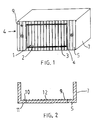
- the reference 1 designates a fog lamp or a long-range projector for a motor vehicle.
- the headlamp 1 comprises a front lens 2 mounted with sealing on a reflector not visible in FIG. 1.
- the reflector has the shape of a hollow metal or plastic body, the concave surface of which is covered with a reflective coating, constituted in practice by a thin layer of aluminum.
- a light source not shown, is placed inside the reflector.
- the lens 2 has ridges 3.
- the lens 2 has a smooth outer face, the striations 3 being formed on the inner face facing the body of the reflector.
- the projector is of rectangular section.
- a hubcap 4 at least partially surrounds the projector 1.
- the hubcap 4 has the general shape of a cylinder with a section corresponding to that of the rectangular projector 1 as shown.
- It has a bottom 5 which has an opening or window 6, the dimensions of which are chosen so that said window 6 surrounds said glass 2, apart from the assembly clearance. It also has a rim 6.
- the hubcap which thus forms a hollow body, comprises means cooperating with the projector 1 for their relative fixing so that the glass 2 is flush with said window 6.
- Fixing means 8 are provided for fixing the headlamp assembly 1-trim 4 to the body of a motor vehicle, in particular in a housing provided for this purpose.
- the hubcap 4 thus makes it possible to adapt a projector of a determined size to a housing of any larger size.
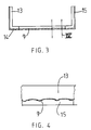
- the reliefs 9 are produced on the internal face 10 of the hubcap, located inside the volume formed by the hubcap, so that the hubcap 4 has an external face 11 smooth.
- the hubcap 4 is made of transparent plastic and an aluminum layer 12 is deposited on the internal face 10 and, consequently, on the reliefs 9. A protective layer covers the aluminum layer 12.
- the deposition of an aluminum layer 12 on the reliefs 9 is particularly difficult to obtain in a uniform manner because they are inside a concave volume.
- the hubcap 4 has a structure with two layers.
- a first layer, said inner layer 13, is made of opaque plastic material dyed in the mass, so as to give the impression of metallization.
- the reliefs 9 are, according to the invention, formed on the convex face 14, or face in reliefs, of said internal layer 13.
- a second layer, called transparent outer layer 15, is molded onto said inner layer 13, on the convex face 14 of the latter.
- the thickness of the external layer 15 is substantially thinner than the internal layer 13.
- the hubcap of Figures 3 and 4 is advantageously produced by the two-color injection process or by the two-material injection process.
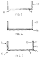
- the hubcap has a two-layer structure similar to that of the hubcap shown in FIGS. 3 and 4.
- the essential difference consists in depositing a thin reflective layer 16 or a shiny appearance on the reliefs 9 formed on the convex face 14 of the internal layer 13.
- An outer layer 15 is molded onto said inner layer on the raised face or convex face 14 of the latter and on said reflective layer 16.
- said reflective layer 16 is deposited on only part of the surface of the internal layer 13, so as to provide at least one zone 17 of direct contact between the internal layer 13 and the external layer 15, which makes it possible to ensure better cohesion of the two layers.
- the zone 17 corresponds to a non-visible part of the hubcap, once it is installed on the vehicle, and it is the part corresponding to the rim 7 of the hubcap.
- the outer layer 15 is made of transparent material 15.
- the internal layer 13 can also, but not necessarily, be made of transparent material.
- tinted material It can also be, as in the previous example, in tinted material.
- the materials of the inner 13 and outer 15 layers are chosen, in the two embodiments, so as to be compatible with each other for good cohesion of the hubcap.
- the hubcap according to the embodiment of Figures 5 to 7, is obtained as follows:
- the inner layer 13 is first molded to the shape of the hubcap 4, having reliefs 9 on a convex face 14 or relief face thereof.
- the blank thus obtained (FIG. 5) is placed in a vacuum metallization enclosure, by providing masks in order to prevent the metallization from reaching an area 17 corresponding to the rim 7 of the hubcap 1. A result is then obtained.
- the metallization of the reliefs 9 presents no difficulty in that they are arranged on a convex face 14.
- the hubcap advantageously has smooth internal and external faces, the reliefs 9 being produced inside the material.
- Reliefs 9 have only been shown on one face corresponding to the bottom 5 of the hubcap 1.
- the hubcap 4, produced according to one of the preceding examples, and the glass 2 form a one-piece assembly.
- the plastic glass 2 is molded onto the hubcap 4 or it is formed during one of the molding phases of the hubcap.
- the glass 2 is made of glass, it is the hubcap 4 which is molded thereon.
- the one-piece assembly is adapted to be attached to a front face of a projector device or the like.
Landscapes
- Engineering & Computer Science (AREA)
- Mechanical Engineering (AREA)
- Non-Portable Lighting Devices Or Systems Thereof (AREA)
- Lighting Device Outwards From Vehicle And Optical Signal (AREA)
- Vehicle Waterproofing, Decoration, And Sanitation Devices (AREA)
Claims (7)
- Zierkappe zum mindestens teilweisen Umgeben einer Reflektor-Vorderscheibe (2) eines Scheinwerfers und insbesondere eines sogenannten Ergänzungsscheinwerfers, wie z.B. eines Weitstrahlers oder eines Nebelscheinwerfers für ein Fahrzeug, wobei die Zierkappe (4) rillenförmige Erhöhungen (9) aufweist, passend zu den Rillen, die auf der dem Reflektor zugewandten Innenseite der genannten Scheibe (2) angebracht sind, um den vom Scheinwerfer ausgehenden Lichtstrahl zu verteilen, gekennzeichnet einerseits durch eine wenigstens zweilagige Struktur (13, 15), deren eine Lage, die sogenannte Außenlage (15), transparent ist, und andererseits dadurch, daß die genannten rillenförmigen Erhöhungen (9) an der Schnittstelle zwischen den genannten beiden Lagen (13, 15) angebracht sind.
- Zierkappe nach Anspruch 1, dadurch gekennzeichnet, daß eine Lage, die sogenannte Innenlage (13), aus einem in der Masse gefärbten Material besteht und auf einer Seite, der sogenannten Reliefseite, Erhöhungen (9), insbesondere in Rillenform, aufweist und daß die genannte transparente Außenlage (15) der genannten Reliefseite überformt ist.
- Zierkappe nach Anspruch 1, dadurch gekennzeichnet, daß eine als Innenlage bezeichnete Lage (13) auf einer Seite, der sogenannten Reliefseite, Erhöhungen (9), insbesondere in Rillenform, aufweist, worauf ein glänzender oder metallischer Überzug (16), wie z.B. Aluminium, aufgebracht ist, und die genannte transparente Außenlage (15) der genannten, so beschichteten Reliefseite überformt ist.
- Zierkappe nach Anspruch 3, dadurch gekennzeichnet, daß der genannte Überzug (16) nur auf einem Teil der genannten Innenlage aufgebracht ist, so daß in bestimmten Bereichen (17) ein direkter Kontakt zwischen der genannten Innenlage (13) und der Außenlage (15) möglich ist und ein besserer Zusammenhalt der Einheit gewährleistet ist.
- Zierkappe nach Anspruch 4 in Form eines zylindrischen Rahmens, der einen Rand (7) und einen Boden (5) mit einer Öffnung (6) aufweist, dadurch gekennzeichnet, daß der Überzug (16) wenigstens den Teil der genannten Innenlage (13) in Anspruch nimmt, der dem genannten offenen Boden (5) entspricht, und daß ein dem genannten Rand (7) entsprechender Bereich (17) der genannten Innenlage wenigstens teilweise in direktem Kontakt mit der genannten transparenten Außenlage (15) ist, was einen besseren Zusammenhalt der zweilagigen Struktur gewährleistet.
- Zierkappe nach einem der vorherigen Ansprüche, dadurch gekennzeichnet, daß sie glatte Innen- und Außenflächen aufweist.
- Zierkappe nach einem der vorherigen Ansprüche, dadurch gekennzeichnet, daß sie mit der Scheibe (2) eine Ein-Block-Konstruktion bildet.
Applications Claiming Priority (2)
| Application Number | Priority Date | Filing Date | Title |
|---|---|---|---|
| FR9002435 | 1990-02-27 | ||
| FR9002435A FR2658766B1 (fr) | 1990-02-27 | 1990-02-27 | Enjoliveur destine a entourer, au moins partiellement, une glace plus particulierement d'un projecteur de vehicule automobile. |
Publications (2)
| Publication Number | Publication Date |
|---|---|
| EP0445007A1 EP0445007A1 (de) | 1991-09-04 |
| EP0445007B1 true EP0445007B1 (de) | 1993-12-29 |
Family
ID=9394184
Family Applications (1)
| Application Number | Title | Priority Date | Filing Date |
|---|---|---|---|
| EP91400483A Expired - Lifetime EP0445007B1 (de) | 1990-02-27 | 1991-02-22 | Zierkappe zum wenigstens teilweisen Umgeben einer Fahrzeugscheinwerferscheibe |
Country Status (6)
| Country | Link |
|---|---|
| US (1) | US5156453A (de) |
| EP (1) | EP0445007B1 (de) |
| JP (1) | JPH04218442A (de) |
| DE (1) | DE69100858T2 (de) |
| ES (1) | ES2049529T3 (de) |
| FR (1) | FR2658766B1 (de) |
Families Citing this family (2)
| Publication number | Priority date | Publication date | Assignee | Title |
|---|---|---|---|---|
| FR2757808B1 (fr) * | 1996-12-26 | 1999-03-19 | Valeo Vision | Projecteur de vehicule automobile pourvu d'un enjoliveur de style |
| FR3102395B1 (fr) | 2019-10-25 | 2023-04-14 | Psa Automobiles Sa | Glace de projecteur pour véhicule automobile et moule à injection destiné à la réalisation de ladite glace |
Family Cites Families (10)
| Publication number | Priority date | Publication date | Assignee | Title |
|---|---|---|---|---|
| DE626233C (de) * | 1934-06-08 | 1936-02-22 | Walther Thorner Dr | Abblendscheibe und Blendschutzbrille, z.B. fuer Kraftfahrzeugscheinwerfer bzw. Kraftfahrer |
| GB537896A (en) * | 1940-01-18 | 1941-07-11 | Frederick Mason | Improvements in or relating to lamps |
| GB1591013A (en) * | 1978-05-30 | 1981-06-10 | Lucas Industries Ltd | High contrast lamp assembly |
| DE3103840A1 (de) * | 1981-02-05 | 1982-09-02 | Friedrich Turnwald | "kraftfahrzeugleuchte, insbesondere scheinwerfer" |
| DE3108059C2 (de) * | 1981-03-04 | 1984-01-26 | Daimler-Benz Ag, 7000 Stuttgart | Streuscheibe für Scheinwerfer von Fahrzeugen |
| JPS59138050A (ja) * | 1983-01-27 | 1984-08-08 | トヨタ自動車株式会社 | ランプ構造 |
| US4722023A (en) * | 1984-05-15 | 1988-01-26 | Koito Seisakusho Co., Ltd. | Lamp assembly for emitting a beam of light at an angle to its optical axis |
| US4654761A (en) * | 1986-02-28 | 1987-03-31 | General Motors Corporation | Periscopic vehicle lamp lens and lens arrangement including same |
| DE3636383A1 (de) * | 1986-10-25 | 1988-04-28 | Swf Auto Electric Gmbh | Signalleuchte, insbesondere fuer kraftfahrzeuge |
| US4972302A (en) * | 1988-07-18 | 1990-11-20 | Stanley Electric Co., Ltd. | Vehicle lamp having inner lens and reflector |
-
1990
- 1990-02-27 FR FR9002435A patent/FR2658766B1/fr not_active Expired - Fee Related
-
1991
- 1991-02-22 EP EP91400483A patent/EP0445007B1/de not_active Expired - Lifetime
- 1991-02-22 ES ES91400483T patent/ES2049529T3/es not_active Expired - Lifetime
- 1991-02-22 DE DE91400483T patent/DE69100858T2/de not_active Expired - Fee Related
- 1991-02-22 US US07/659,261 patent/US5156453A/en not_active Expired - Fee Related
- 1991-02-27 JP JP3053734A patent/JPH04218442A/ja active Pending
Also Published As
| Publication number | Publication date |
|---|---|
| FR2658766B1 (fr) | 1993-04-30 |
| ES2049529T3 (es) | 1994-04-16 |
| US5156453A (en) | 1992-10-20 |
| FR2658766A1 (fr) | 1991-08-30 |
| JPH04218442A (ja) | 1992-08-10 |
| DE69100858T2 (de) | 1994-04-21 |
| DE69100858D1 (de) | 1994-02-10 |
| EP0445007A1 (de) | 1991-09-04 |
Similar Documents
| Publication | Publication Date | Title |
|---|---|---|
| FR2574759A1 (fr) | Couvercle obturateur en matiere plastique, notamment pour fermer un orifice menage dans une carrosserie d'automobile | |
| FR2463436A1 (fr) | Montre a elements de forme profilee, notamment non circulaire | |
| EP1172259B1 (de) | Karosserieausführung mit mindestens einem mit einem Film umgossenen Teil | |
| EP0445007B1 (de) | Zierkappe zum wenigstens teilweisen Umgeben einer Fahrzeugscheinwerferscheibe | |
| FR2544839A1 (fr) | Projecteur notamment destine a un vehicule automobile | |
| EP1120303A1 (de) | Kraftfahrzeugsflügel aus Kunststoff und Fahrzeug mit solchem Flügel | |
| EP0013245B1 (de) | Verbesserungen an Kraftfahrzeug-Scheinwerfern | |
| EP0586279A1 (de) | Einstückige Frontplatte für Kraftfahrzeuge | |
| EP0984222B1 (de) | Kraftfahrzeugscheinwerfer mit querliegender Lampe und mit verbesserten Lampenmontagemitteln | |
| FR2643028A1 (fr) | Cassette a miroir, notamment pour pare-soleil d'un habitacle d'automobile et procede de fabrication | |
| EP0643256B1 (de) | Gehäuse und Abdeckkappe für Kraftfahrzeugscheinwerfer oder -Signallampe | |
| EP0692670B1 (de) | Verfahren zur Herstellung von direktem Licht abschirmenden Blenden für Kfz-Scheinwerfer und Scheinwerfer mit solchen Blenden | |
| EP0718545A1 (de) | Kraftfahrzeugscheinwerfer mit einem das direkt emittierende Licht abschirmenden Element mit verbessertem Aussehen | |
| FR2564945A1 (fr) | Perfectionnements aux projecteurs de vehicules automobiles. | |
| FR2600145A1 (fr) | Projecteur ventile pour vehicules automobiles | |
| FR2669863A1 (fr) | Vitre pivotante notamment pour vehicule automobile, joint d'etancheite d'une telle vitre et son procede de fabrication. | |
| EP4352407B1 (de) | Gehäuse für ein optisches modul einer beleuchtungs- und/oder signalvorrichtung eines kraftfahrzeuges | |
| FR2769005A1 (fr) | Capsule service pour recipient distributeur | |
| FR2749237A1 (fr) | Dispositif d'eclairage ou de signalisation a joint surmoule pour vehicule | |
| FR2709811A1 (fr) | Projecteur d'aspect intérieur amélioré pour véhicule automobile. | |
| EP0771691B1 (de) | Signalleuchte mit Schirm aus zwei Materialien für Fahrzeugheckscheibe | |
| EP0669495B1 (de) | Lichtscheibe für Beleuchtungssystem oder Signalleuchtungssystem eines Fahrzeuges und damit ausgestattete Anlage | |
| FR2754502A1 (fr) | Piece d'habillage de carrosserie, dite "cache-retroviseur", pour portiere de vehicule automobile | |
| FR2478263A1 (fr) | Procede pour la fabrication d'un phare ou lampe d'eclairage pour vehicule automobile et phare conforme a celui ainsi obtenu | |
| FR2727913A1 (fr) | Projecteur de vehicule automobile, comportant des moyens de retenue de glace et d'enjolivement perfectionnes |
Legal Events
| Date | Code | Title | Description |
|---|---|---|---|
| PUAI | Public reference made under article 153(3) epc to a published international application that has entered the european phase |
Free format text: ORIGINAL CODE: 0009012 |
|
| AK | Designated contracting states |
Kind code of ref document: A1 Designated state(s): DE ES GB IT |
|
| 17P | Request for examination filed |
Effective date: 19920108 |
|
| 17Q | First examination report despatched |
Effective date: 19930318 |
|
| GRAA | (expected) grant |
Free format text: ORIGINAL CODE: 0009210 |
|
| AK | Designated contracting states |
Kind code of ref document: B1 Designated state(s): DE ES GB IT |
|
| ITF | It: translation for a ep patent filed | ||
| REF | Corresponds to: |
Ref document number: 69100858 Country of ref document: DE Date of ref document: 19940210 |
|
| GBT | Gb: translation of ep patent filed (gb section 77(6)(a)/1977) |
Effective date: 19940309 |
|
| REG | Reference to a national code |
Ref country code: ES Ref legal event code: FG2A Ref document number: 2049529 Country of ref document: ES Kind code of ref document: T3 |
|
| PLBE | No opposition filed within time limit |
Free format text: ORIGINAL CODE: 0009261 |
|
| STAA | Information on the status of an ep patent application or granted ep patent |
Free format text: STATUS: NO OPPOSITION FILED WITHIN TIME LIMIT |
|
| 26N | No opposition filed | ||
| ITTA | It: last paid annual fee | ||
| PGFP | Annual fee paid to national office [announced via postgrant information from national office to epo] |
Ref country code: DE Payment date: 20000212 Year of fee payment: 10 |
|
| PGFP | Annual fee paid to national office [announced via postgrant information from national office to epo] |
Ref country code: GB Payment date: 20000215 Year of fee payment: 10 |
|
| PG25 | Lapsed in a contracting state [announced via postgrant information from national office to epo] |
Ref country code: GB Free format text: LAPSE BECAUSE OF NON-PAYMENT OF DUE FEES Effective date: 20010222 |
|
| GBPC | Gb: european patent ceased through non-payment of renewal fee |
Effective date: 20010222 |
|
| PG25 | Lapsed in a contracting state [announced via postgrant information from national office to epo] |
Ref country code: DE Free format text: LAPSE BECAUSE OF NON-PAYMENT OF DUE FEES Effective date: 20011201 |
|
| PG25 | Lapsed in a contracting state [announced via postgrant information from national office to epo] |
Ref country code: IT Free format text: LAPSE BECAUSE OF NON-PAYMENT OF DUE FEES;WARNING: LAPSES OF ITALIAN PATENTS WITH EFFECTIVE DATE BEFORE 2007 MAY HAVE OCCURRED AT ANY TIME BEFORE 2007. THE CORRECT EFFECTIVE DATE MAY BE DIFFERENT FROM THE ONE RECORDED. Effective date: 20050222 |
|
| PGFP | Annual fee paid to national office [announced via postgrant information from national office to epo] |
Ref country code: ES Payment date: 20060221 Year of fee payment: 16 |
|
| REG | Reference to a national code |
Ref country code: ES Ref legal event code: FD2A Effective date: 20070223 |
|
| PG25 | Lapsed in a contracting state [announced via postgrant information from national office to epo] |
Ref country code: ES Free format text: LAPSE BECAUSE OF NON-PAYMENT OF DUE FEES Effective date: 20070223 |