EP0445082A2 - Connection for foldable tubular members - Google Patents
Connection for foldable tubular members Download PDFInfo
- Publication number
- EP0445082A2 EP0445082A2 EP91830031A EP91830031A EP0445082A2 EP 0445082 A2 EP0445082 A2 EP 0445082A2 EP 91830031 A EP91830031 A EP 91830031A EP 91830031 A EP91830031 A EP 91830031A EP 0445082 A2 EP0445082 A2 EP 0445082A2
- Authority
- EP
- European Patent Office
- Prior art keywords
- joint
- channel
- hole
- elements
- clothes
- Prior art date
- Legal status (The legal status is an assumption and is not a legal conclusion. Google has not performed a legal analysis and makes no representation as to the accuracy of the status listed.)
- Granted
Links
- 230000000903 blocking effect Effects 0.000 claims description 3
- 239000000853 adhesive Substances 0.000 claims description 2
- 230000001070 adhesive effect Effects 0.000 claims description 2
- 238000000034 method Methods 0.000 description 1
- 238000000465 moulding Methods 0.000 description 1
Images
Classifications
-
- D—TEXTILES; PAPER
- D06—TREATMENT OF TEXTILES OR THE LIKE; LAUNDERING; FLEXIBLE MATERIALS NOT OTHERWISE PROVIDED FOR
- D06F—LAUNDERING, DRYING, IRONING, PRESSING OR FOLDING TEXTILE ARTICLES
- D06F57/00—Supporting means, other than simple clothes-lines, for linen or garments to be dried or aired
- D06F57/08—Folding stands
Definitions
- the present invention generally relates to a joint for connecting tubular members designed to be folded one on the other, and more particularly a joint suitable for connecting tubes which form the folding legs of a space-saving clothes-horse.
- Clothes-horses with a grid and possible extension grids held by two pairs of crossed legs which are pivoted to each other and in which the legs of a first pair have a central articulation which allows for them to fold so as to close the clothes-horse, are already known.
- said clothes-horses the folding of the legs with central articulation and subsequent accidental closure of the clothes-horse are possible in the case of knocks or incorrect movements.
- An uncontrolled closure of the clothes-horse can however be dangerous for people, especially children and it is therefore strongly advisable not to use.
- the object of the present invention is to propose a joint for connecting two foldable elements, one on top of the other, such as the tubular members which form the folding legs of a clothes- horse.
- the joint has safety means which block the elements connected to each other in an open position, that is to say aligned to each other.
- a second object of this invention is to propose a joint made as a single piece advantageously achieved through moulding and with a new configuration which allows it to be easily fitted onto the elements to be connected.
- a further object of the invention is to propose a joint made as a single piece which contemporarily connects the two folding elements and automatically blocks the elements so as to avoid an accidental folding when they are aligned to each other.
- the joint in question is made of a single piece (10) with a part which delimits a hole (11) open towards an end of the body and a U-shaped part which delimits a channel (12) open on one side of said body.
- protruding parts (12b) pointing towards the centre and designed to reduce the opening of the channel (12) are formed (Fig. 3).
- the above described joint is used to connect two tubes (13, 14) which are foldable on top of each other due to the rotation of one of them.
- Said tubular elements (13, 14) can be made up of the two tubes which form the foldable legs (15) of a clothes-horse (16) like the one in Fig. 4 of the drawing.
- the joint is fitted to the two tubular elements (13,14) to be connected by forcing, and/or through the use of adhesive, and/or with a pin, an end of the lower element (13) into the hole (11) of the body (10) and by pivoting the lower end of the upper element (14) into the channel (12) through the use of a tranversal pin (14a).
- the joint is rigidly constrained to the lower element (13) whilst the upper element (14) is foldable on the first so as to rotate round the relative pin (14a).
- the element (14) is then forced to clip into the channel (12) through a tight opening of the protruding parts (12b), making use of the elasticity of the tabs (12a) which define the hole itself.
- the element is then blocked into the hole and is therefore in position due to said protruding parts (12b) (Fig 3) which prevent the folding of the elements and therefore the accidental closing of a clothes-horse with folding legs.
Landscapes
- Engineering & Computer Science (AREA)
- Textile Engineering (AREA)
- Non-Disconnectible Joints And Screw-Threaded Joints (AREA)
- Earth Drilling (AREA)
- Joints Allowing Movement (AREA)
- Quick-Acting Or Multi-Walled Pipe Joints (AREA)
- Branch Pipes, Bends, And The Like (AREA)
- Tubes (AREA)
- Mutual Connection Of Rods And Tubes (AREA)
Abstract
Description
- The present invention generally relates to a joint for connecting tubular members designed to be folded one on the other, and more particularly a joint suitable for connecting tubes which form the folding legs of a space-saving clothes-horse.
- Clothes-horses with a grid and possible extension grids held by two pairs of crossed legs which are pivoted to each other and in which the legs of a first pair have a central articulation which allows for them to fold so as to close the clothes-horse, are already known. In said clothes-horses, the folding of the legs with central articulation and subsequent accidental closure of the clothes-horse are possible in the case of knocks or incorrect movements. An uncontrolled closure of the clothes-horse can however be dangerous for people, especially children and it is therefore strongly advisable not to use.
- For this reason, a way of blocking the articulation with the legs open has already been proposed. This method though requires the fitting of an extra element that interacts with the joint which connects the folding elements.
- The object of the present invention is to propose a joint for connecting two foldable elements, one on top of the other, such as the tubular members which form the folding legs of a clothes- horse. The joint has safety means which block the elements connected to each other in an open position, that is to say aligned to each other.
- A second object of this invention is to propose a joint made as a single piece advantageously achieved through moulding and with a new configuration which allows it to be easily fitted onto the elements to be connected.
- A further object of the invention is to propose a joint made as a single piece which contemporarily connects the two folding elements and automatically blocks the elements so as to avoid an accidental folding when they are aligned to each other.
- Said aims are achieved with a joint which is in accordance with claim 1.
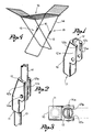
- An example of realization of the joint will however be described with references to the attached drawing in which:
- Fig. 1 is a perspective view of the joint;
- Fig. 2 is the joint connecting two elements;
- Fig. 3 is a cross section of the joint in the blocking position ; and
- Fig. 4 is a clothes-horse with a pair of legs which can be folded due to the joint which is in accordance with the invention.
- The joint in question is made of a single piece (10) with a part which delimits a hole (11) open towards an end of the body and a U-shaped part which delimits a channel (12) open on one side of said body. On the inside of the facing tabs (12a) of the U-shaped part, protruding parts (12b) pointing towards the centre and designed to reduce the opening of the channel (12) are formed (Fig. 3).
- The above described joint is used to connect two tubes (13, 14) which are foldable on top of each other due to the rotation of one of them. Said tubular elements (13, 14) can be made up of the two tubes which form the foldable legs (15) of a clothes-horse (16) like the one in Fig. 4 of the drawing.
- The joint is fitted to the two tubular elements (13,14) to be connected by forcing, and/or through the use of adhesive, and/or with a pin, an end of the lower element (13) into the hole (11) of the body (10) and by pivoting the lower end of the upper element (14) into the channel (12) through the use of a tranversal pin (14a). In this way the joint is rigidly constrained to the lower element (13) whilst the upper element (14) is foldable on the first so as to rotate round the relative pin (14a). When the two elements (13, 14) have to be opened, in other words aligned, the upper element is rotated until it is blocked into the channel (12) of the joint.
- The element (14) is then forced to clip into the channel (12) through a tight opening of the protruding parts (12b), making use of the elasticity of the tabs (12a) which define the hole itself. The element is then blocked into the hole and is therefore in position due to said protruding parts (12b) (Fig 3) which prevent the folding of the elements and therefore the accidental closing of a clothes-horse with folding legs.
Claims (2)
Applications Claiming Priority (2)
| Application Number | Priority Date | Filing Date | Title |
|---|---|---|---|
| IT6935U IT221220Z2 (it) | 1990-02-26 | 1990-02-26 | Giunto per il collegamento di due elementi tubolari ripiegabili l'unosull'altro |
| IT693590U | 1990-02-26 |
Publications (3)
| Publication Number | Publication Date |
|---|---|
| EP0445082A2 true EP0445082A2 (en) | 1991-09-04 |
| EP0445082A3 EP0445082A3 (en) | 1992-01-22 |
| EP0445082B1 EP0445082B1 (en) | 1995-09-06 |
Family
ID=11122501
Family Applications (1)
| Application Number | Title | Priority Date | Filing Date |
|---|---|---|---|
| EP91830031A Expired - Lifetime EP0445082B1 (en) | 1990-02-26 | 1991-02-04 | Connection for foldable tubular members |
Country Status (4)
| Country | Link |
|---|---|
| EP (1) | EP0445082B1 (en) |
| AT (1) | ATE127545T1 (en) |
| DE (1) | DE69112673T2 (en) |
| IT (1) | IT221220Z2 (en) |
Cited By (5)
| Publication number | Priority date | Publication date | Assignee | Title |
|---|---|---|---|---|
| EP0609476A1 (en) * | 1993-02-05 | 1994-08-10 | LEIFHEIT Aktiengesellschaft | Collapsible drying stand |
| EP1008686A1 (en) * | 1998-11-24 | 2000-06-14 | Zumbühl & Co. Handelsagentur | Clothes drying rack |
| GR20060100665A (en) * | 2006-12-05 | 2008-07-31 | Ευαγγελος Αντωνιου Συλιβος | Promptly assembled clothes-horse by plastic connectors with sleeves of rotating connection of the metal pipes. |
| EP3202971A1 (en) * | 2016-02-04 | 2017-08-09 | Rörets Industrier AB | Foldable clothes care product |
| GB2618417A (en) * | 2022-03-01 | 2023-11-08 | Metaltex Spa | Clotheshorse with improved load capacity |
Families Citing this family (1)
| Publication number | Priority date | Publication date | Assignee | Title |
|---|---|---|---|---|
| DE10202519B9 (en) * | 2002-01-23 | 2005-05-19 | Ps Power Service Ag | Collapsible clotheshorse |
Family Cites Families (3)
| Publication number | Priority date | Publication date | Assignee | Title |
|---|---|---|---|---|
| GB858835A (en) * | 1958-06-11 | 1961-01-18 | Aubrey George Carroll | Improvements in domestic clothes drying apparatus |
| FR2511403A2 (en) * | 1981-08-13 | 1983-02-18 | Chapuit Jacques | Clothes drier stand with supporting cross bar - having common pivot and position locking clamp |
| DE8905090U1 (en) * | 1989-04-22 | 1989-08-10 | FRZ Metallwarenfabrik Friedrich Ruschitzka, 6921 Zuzenhausen | Fall protection for locking unfolded devices, preferably clothes racks and similar foldable equipment |
-
1990
- 1990-02-26 IT IT6935U patent/IT221220Z2/it active IP Right Grant
-
1991
- 1991-02-04 EP EP91830031A patent/EP0445082B1/en not_active Expired - Lifetime
- 1991-02-04 DE DE69112673T patent/DE69112673T2/en not_active Expired - Fee Related
- 1991-02-04 AT AT91830031T patent/ATE127545T1/en not_active IP Right Cessation
Cited By (6)
| Publication number | Priority date | Publication date | Assignee | Title |
|---|---|---|---|---|
| EP0609476A1 (en) * | 1993-02-05 | 1994-08-10 | LEIFHEIT Aktiengesellschaft | Collapsible drying stand |
| EP1008686A1 (en) * | 1998-11-24 | 2000-06-14 | Zumbühl & Co. Handelsagentur | Clothes drying rack |
| GR20060100665A (en) * | 2006-12-05 | 2008-07-31 | Ευαγγελος Αντωνιου Συλιβος | Promptly assembled clothes-horse by plastic connectors with sleeves of rotating connection of the metal pipes. |
| EP3202971A1 (en) * | 2016-02-04 | 2017-08-09 | Rörets Industrier AB | Foldable clothes care product |
| GB2618417A (en) * | 2022-03-01 | 2023-11-08 | Metaltex Spa | Clotheshorse with improved load capacity |
| GB2618417B (en) * | 2022-03-01 | 2024-06-05 | Metaltex Spa | Clotheshorse with improved load capacity |
Also Published As
| Publication number | Publication date |
|---|---|
| ATE127545T1 (en) | 1995-09-15 |
| EP0445082B1 (en) | 1995-09-06 |
| DE69112673D1 (en) | 1995-10-12 |
| EP0445082A3 (en) | 1992-01-22 |
| IT9006935U1 (en) | 1991-08-27 |
| IT9006935V0 (en) | 1990-02-26 |
| DE69112673T2 (en) | 1996-04-18 |
| IT221220Z2 (it) | 1994-02-17 |
Similar Documents
| Publication | Publication Date | Title |
|---|---|---|
| US4477947A (en) | Drawstring fastener | |
| US4055179A (en) | Valve for urinary drainage container or similar article | |
| EP0507012B1 (en) | Lower joint folding preventing device for one touch type dome shaped tent | |
| US1757260A (en) | Folding table | |
| KR890014945A (en) | Connector for narrow pipe | |
| CN207609244U (en) | A kind of support frame and tent of tent | |
| JPH04131588A (en) | Joint member for circular canal | |
| EP0445082B1 (en) | Connection for foldable tubular members | |
| GB2301036A (en) | Needle protector | |
| GB2189693A (en) | Unitary collapsible coat hanger | |
| US5305771A (en) | Umbrella with rounded rib terminals | |
| CN109779383A (en) | Rod piece bent joint, appliance for releasing single open form tent bracket and tent cluster | |
| US5806545A (en) | Control cords of an automatic umbrella | |
| US5158102A (en) | Umbrella frame having folding ear structures | |
| EP0732251A4 (en) | Grip rod of baby carriage | |
| CA2191904A1 (en) | Rod member connector for a folding chair | |
| EP0303816A3 (en) | Valve spindle | |
| US3119568A (en) | Trouble light guard | |
| CA2157842A1 (en) | Extension Ladder with Telescopic Legs | |
| US20220298862A1 (en) | Step Ladder Folding Assist | |
| EP0432110A2 (en) | Folding clothes horse | |
| KR200202948Y1 (en) | Transformable toy | |
| GB2084645A (en) | Improvements in and relating to hinges for umbrella frames | |
| CN219020415U (en) | Bundle pocket convenient to store | |
| EP0736790A1 (en) | Elastic hinge for spectacles |
Legal Events
| Date | Code | Title | Description |
|---|---|---|---|
| PUAI | Public reference made under article 153(3) epc to a published international application that has entered the european phase |
Free format text: ORIGINAL CODE: 0009012 |
|
| AK | Designated contracting states |
Kind code of ref document: A2 Designated state(s): AT CH DE DK ES FR GR IT LI NL |
|
| PUAL | Search report despatched |
Free format text: ORIGINAL CODE: 0009013 |
|
| AK | Designated contracting states |
Kind code of ref document: A3 Designated state(s): AT CH DE DK ES FR GR IT LI NL |
|
| 17P | Request for examination filed |
Effective date: 19920706 |
|
| 17Q | First examination report despatched |
Effective date: 19940328 |
|
| GRAA | (expected) grant |
Free format text: ORIGINAL CODE: 0009210 |
|
| AK | Designated contracting states |
Kind code of ref document: B1 Designated state(s): AT CH DE DK ES FR GR IT LI NL |
|
| PG25 | Lapsed in a contracting state [announced via postgrant information from national office to epo] |
Ref country code: IT Free format text: LAPSE BECAUSE OF FAILURE TO SUBMIT A TRANSLATION OF THE DESCRIPTION OR TO PAY THE FEE WITHIN THE PRE;WARNING: LAPSES OF ITALIAN PATENTS WITH EFFECTIVE DATE BEFORE 2007 MAY HAVE OCCURRED AT ANY TIME BEFORE 2007. THE CORRECT EFFECTIVE DATE MAY BE DIFFERENT FROM THE ONE RECORDED.SCRIBED TIME-LIMIT Effective date: 19950906 Ref country code: FR Effective date: 19950906 Ref country code: GR Free format text: LAPSE BECAUSE OF FAILURE TO SUBMIT A TRANSLATION OF THE DESCRIPTION OR TO PAY THE FEE WITHIN THE PRESCRIBED TIME-LIMIT Effective date: 19950906 Ref country code: DK Effective date: 19950906 Ref country code: LI Effective date: 19950906 Ref country code: NL Free format text: LAPSE BECAUSE OF FAILURE TO SUBMIT A TRANSLATION OF THE DESCRIPTION OR TO PAY THE FEE WITHIN THE PRESCRIBED TIME-LIMIT Effective date: 19950906 Ref country code: ES Free format text: THE PATENT HAS BEEN ANNULLED BY A DECISION OF A NATIONAL AUTHORITY Effective date: 19950906 Ref country code: AT Effective date: 19950906 Ref country code: CH Effective date: 19950906 |
|
| REF | Corresponds to: |
Ref document number: 127545 Country of ref document: AT Date of ref document: 19950915 Kind code of ref document: T |
|
| REF | Corresponds to: |
Ref document number: 69112673 Country of ref document: DE Date of ref document: 19951012 |
|
| NLV1 | Nl: lapsed or annulled due to failure to fulfill the requirements of art. 29p and 29m of the patents act | ||
| EN | Fr: translation not filed | ||
| REG | Reference to a national code |
Ref country code: CH Ref legal event code: PL |
|
| PLBE | No opposition filed within time limit |
Free format text: ORIGINAL CODE: 0009261 |
|
| STAA | Information on the status of an ep patent application or granted ep patent |
Free format text: STATUS: NO OPPOSITION FILED WITHIN TIME LIMIT |
|
| 26N | No opposition filed | ||
| PGFP | Annual fee paid to national office [announced via postgrant information from national office to epo] |
Ref country code: DE Payment date: 20070226 Year of fee payment: 17 |
|
| PG25 | Lapsed in a contracting state [announced via postgrant information from national office to epo] |
Ref country code: DE Free format text: LAPSE BECAUSE OF NON-PAYMENT OF DUE FEES Effective date: 20080902 |