EP0445100A1 - Zerstäubungsturbine - Google Patents
Zerstäubungsturbine Download PDFInfo
- Publication number
- EP0445100A1 EP0445100A1 EP91870035A EP91870035A EP0445100A1 EP 0445100 A1 EP0445100 A1 EP 0445100A1 EP 91870035 A EP91870035 A EP 91870035A EP 91870035 A EP91870035 A EP 91870035A EP 0445100 A1 EP0445100 A1 EP 0445100A1
- Authority
- EP
- European Patent Office
- Prior art keywords
- turbine
- atomization
- turbine according
- motor
- blades
- Prior art date
- Legal status (The legal status is an assumption and is not a legal conclusion. Google has not performed a legal analysis and makes no representation as to the accuracy of the status listed.)
- Withdrawn
Links
Images


Classifications
-
- B—PERFORMING OPERATIONS; TRANSPORTING
- B05—SPRAYING OR ATOMISING IN GENERAL; APPLYING FLUENT MATERIALS TO SURFACES, IN GENERAL
- B05B—SPRAYING APPARATUS; ATOMISING APPARATUS; NOZZLES
- B05B3/00—Spraying or sprinkling apparatus with moving outlet elements or moving deflecting elements
- B05B3/02—Spraying or sprinkling apparatus with moving outlet elements or moving deflecting elements with rotating elements
- B05B3/10—Spraying or sprinkling apparatus with moving outlet elements or moving deflecting elements with rotating elements discharging over substantially the whole periphery of the rotating member
- B05B3/1057—Spraying or sprinkling apparatus with moving outlet elements or moving deflecting elements with rotating elements discharging over substantially the whole periphery of the rotating member with at least two outlets, other than gas and cleaning fluid outlets, for discharging, selectively or not, different or identical liquids or other fluent materials on the rotating element
-
- B—PERFORMING OPERATIONS; TRANSPORTING
- B05—SPRAYING OR ATOMISING IN GENERAL; APPLYING FLUENT MATERIALS TO SURFACES, IN GENERAL
- B05B—SPRAYING APPARATUS; ATOMISING APPARATUS; NOZZLES
- B05B3/00—Spraying or sprinkling apparatus with moving outlet elements or moving deflecting elements
- B05B3/02—Spraying or sprinkling apparatus with moving outlet elements or moving deflecting elements with rotating elements
- B05B3/10—Spraying or sprinkling apparatus with moving outlet elements or moving deflecting elements with rotating elements discharging over substantially the whole periphery of the rotating member
- B05B3/1007—Spraying or sprinkling apparatus with moving outlet elements or moving deflecting elements with rotating elements discharging over substantially the whole periphery of the rotating member characterised by the rotating member
-
- B—PERFORMING OPERATIONS; TRANSPORTING
- B05—SPRAYING OR ATOMISING IN GENERAL; APPLYING FLUENT MATERIALS TO SURFACES, IN GENERAL
- B05B—SPRAYING APPARATUS; ATOMISING APPARATUS; NOZZLES
- B05B3/00—Spraying or sprinkling apparatus with moving outlet elements or moving deflecting elements
- B05B3/02—Spraying or sprinkling apparatus with moving outlet elements or moving deflecting elements with rotating elements
- B05B3/10—Spraying or sprinkling apparatus with moving outlet elements or moving deflecting elements with rotating elements discharging over substantially the whole periphery of the rotating member
- B05B3/105—Fan or ventilator arrangements therefor
Definitions
- the present invention relates to spraying devices and relates to a rotary atomizer system.
- the spraying of active material uses pressure atomization, that is to say by tearing a liquid stream through an orifice.
- active material such as insecticides, fungicides, anti-weeds, etc.
- pressure atomization that is to say by tearing a liquid stream through an orifice.
- the spectrum of the diameter of the drops created by this system is very wide and is a function of all the parameters of the system, pressure, flow rate, diameter of the orifice, etc., which complicates its regulation.
- an atomization turbine according to the invention is characterized in that it is in the form of a squirrel cage fan turbine, in that the blades are curved or straight, and in that inside the turbine are annularly distributed around the axis of the turbine and in a symmetrical manner at the base of the blades one or more fixed, solid, perforated injection pipes or soft.
- the internal and / or external faces of the blades are provided with fine grooving and / or end in fine toothing.
- the stationary injector pipe (s), the orifices of which are placed perpendicular to the blades of the turbine, are distributed either parallel or helically to the axis of the turbine.
- the atomizing turbine is fixed at the end of the motor shaft and the injectors are integral with the body of said motor.
- the atomization turbine is mounted on a bearing placed on an axis fixed to said machine or to the wing of the plane, either using an appropriate flange, or screwed directly onto the nozzle of the jet holder.
- the atomizing turbine is associated with a means producing around it a current of air.
- the atomizing turbine is included inside a casing, so as to allow the air charged with droplets produced by the turbine to be directed laterally.
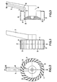
- the atomization turbine 1 is similar to a squirrel cage fan turbine and it has a fine toothing at the end of its blades 2.
- Injector pipes 4, comprising orifices 5 which are advantageously placed in the direction opposite to the flow of the liquid to be sprayed, are distributed symmetrically inside the turbine, at the base of the blades and parallel to the axis of the turbine.
- injectors 4 are fixed, they do not rotate. Their number depends on the desired flow range.
- the atomization turbine 1 is driven by the air stream, in which it is placed.
- the turbine In the case of a spraying machine producing an air current or in the case of aerial spraying, the turbine is mounted on two bearings 6, themselves placed on an axis fixed to the machine or to the wing of the aircraft. using a profile upright 7.
- the speed of rotation is regulated by a system regulating the air flow entering the turbine. This air passes through the blades, drives the atomizer and increases the atomization of the product to be sprayed injected at the base of the blades by the injector pipes 4, which are fixed annularly around the fixed axis and / or to the upright connecting l machine axis.
- the atomization turbine 1 is mounted directly on the axes of the hydraulic drive motor 8.
- Injector pipes 4 having injection orifices 5 are distributed symmetrically with the interior of the turbine, at the base of the blades 2, having a fine toothing 3 at their end, and parallel to the axis of the turbine and are integral with the body of the engine 8.
- the drops produced are of a very small diameter. This is sought to increase the effectiveness of the spraying but, to avoid their dispersion by the wind before they reach their goal, a current of air is produced which forces the drops produced by the atomizer 1 ′ towards their goal.
- an axial fan 12 with two or more orientable blades 13 is placed between this fan 12 and the atomization turbine 1 ′, that is to say over the thickness of the drive motor 8, so as to increase the working width and the efficiency of penetration into the vegetation.
- An aerodynamically shaped cap 15 serving as protection covers the whole, motor 8 - fan 12.
- the blades 2 ′ of the turbine 1 ′ are of curved shape and provided on their face with a fine grooving 16 ending at the end of the blade in fine toothing 3.
- the injection conduits 4 ′ are here provided with a distribution and transfer strip 17 optionally provided with a fine toothing 3.
- Atomization turbines according to the invention are intended to be mounted on existing spraying apparatus, carried, towed by agricultural tractors or mounted on aircraft.
- an existing pressurization system brings the product to be sprayed to each turbine, which has a calibrated orifice placed upstream of the injection system 16.
- the flow rates of the product to be sprayed are varied, independently of the speed of rotation of the turbine.
- the invention makes it possible to disperse extremely small volumes of liquid per unit area with increased treatment efficiency, while providing substantial savings on the cost of the products used and reducing pollution of the soil and the atmosphere.
- the pollution of the soil is reduced, because the atomization turbine does not produce large diameter drops, which do not cling to the goal but fall to the ground and which represent a loss of large volume.
- Air pollution is reduced thanks to the induced air current, which forces the fine drops towards their goal instead of leaving with the wind.
- regulation of the spraying parameters is provided by a computer system, which regulates the pressure of the liquid upstream of the calibration orifice as a function of the speed of advance of the sprayer and of the desired flow rates.
- the drop size spectrum which is the new independently adjustable parameter, is also electronically controlled and regulated.
- a hydraulic pump with variable flow and electronic control is mounted on the sprayer or the tractor.
- the flow rate of the hydraulic pump is automatically regulated according to the drop size requested.
- the system automatically maintains the desired drop size by keeping the rotation speed of the atomization turbines constant, whatever the speed of the hydraulic pump drive, by regulating the flow rate of this pump.
- an atomizing turbine 1 is advantageously included in a suitable casing 18, as shown in FIG. 9.
- This casing 18 makes it possible to direct laterally (arrow x) air charged with droplets produced by the turbine.
- a system for recycling the slurry entering 19 is provided at 20 and 20 ′, so as to recycle contamination of the internal faces of the casing 18, so that this contamination does not disturb the drop spectrum.
- the invention applies to various fields, such as the protection of crops and forests, the application of fertilizers, the fight against invasion (grasshoppers, tsetse flies, mosquitoes, etc.) and all other fields where a liquid should be sprayed.
Landscapes
- Catching Or Destruction (AREA)
Applications Claiming Priority (2)
| Application Number | Priority Date | Filing Date | Title |
|---|---|---|---|
| BE9000226 | 1990-02-27 | ||
| BE9000226A BE1003649A3 (fr) | 1990-02-27 | 1990-02-27 | Turbine d'atomisation. |
Publications (1)
| Publication Number | Publication Date |
|---|---|
| EP0445100A1 true EP0445100A1 (de) | 1991-09-04 |
Family
ID=3884693
Family Applications (1)
| Application Number | Title | Priority Date | Filing Date |
|---|---|---|---|
| EP91870035A Withdrawn EP0445100A1 (de) | 1990-02-27 | 1991-02-27 | Zerstäubungsturbine |
Country Status (2)
| Country | Link |
|---|---|
| EP (1) | EP0445100A1 (de) |
| BE (1) | BE1003649A3 (de) |
Cited By (4)
| Publication number | Priority date | Publication date | Assignee | Title |
|---|---|---|---|---|
| GB2310457A (en) * | 1996-02-22 | 1997-08-27 | Leslie George Abberton | Rotary fuel atomiser |
| WO2002009885A3 (en) * | 2000-07-27 | 2002-08-01 | Cedar Ridge Consultants Ltd | Rotary atomisers |
| CN113236603A (zh) * | 2021-04-27 | 2021-08-10 | 翁玉庆 | 一种储水喷雾吸气排气叶轮 |
| CN119746604A (zh) * | 2024-12-18 | 2025-04-04 | 常州大学 | 一种模块化二氧化碳脱碳塔 |
Citations (5)
| Publication number | Priority date | Publication date | Assignee | Title |
|---|---|---|---|---|
| GB722527A (en) * | 1951-12-12 | 1955-01-26 | Bals Edward Julius | Improvements in or relating to atomisers |
| US3706417A (en) * | 1971-01-29 | 1972-12-19 | King Around Products Inc | Liquid spraying method and apparatus |
| US4037789A (en) * | 1973-12-27 | 1977-07-26 | Shunji Nishimura | Aerosol-particle dispenser |
| GB2057299A (en) * | 1979-08-29 | 1981-04-01 | Micronair Aerial | Spraying apparatus |
| US4795095A (en) * | 1986-09-08 | 1989-01-03 | Shepard Industries, Inc. | Rotary atomizer |
-
1990
- 1990-02-27 BE BE9000226A patent/BE1003649A3/fr not_active IP Right Cessation
-
1991
- 1991-02-27 EP EP91870035A patent/EP0445100A1/de not_active Withdrawn
Patent Citations (5)
| Publication number | Priority date | Publication date | Assignee | Title |
|---|---|---|---|---|
| GB722527A (en) * | 1951-12-12 | 1955-01-26 | Bals Edward Julius | Improvements in or relating to atomisers |
| US3706417A (en) * | 1971-01-29 | 1972-12-19 | King Around Products Inc | Liquid spraying method and apparatus |
| US4037789A (en) * | 1973-12-27 | 1977-07-26 | Shunji Nishimura | Aerosol-particle dispenser |
| GB2057299A (en) * | 1979-08-29 | 1981-04-01 | Micronair Aerial | Spraying apparatus |
| US4795095A (en) * | 1986-09-08 | 1989-01-03 | Shepard Industries, Inc. | Rotary atomizer |
Cited By (6)
| Publication number | Priority date | Publication date | Assignee | Title |
|---|---|---|---|---|
| GB2310457A (en) * | 1996-02-22 | 1997-08-27 | Leslie George Abberton | Rotary fuel atomiser |
| GB2310457B (en) * | 1996-02-22 | 1999-09-01 | Leslie George Abberton | A rotary fuel atomizer |
| WO2002009885A3 (en) * | 2000-07-27 | 2002-08-01 | Cedar Ridge Consultants Ltd | Rotary atomisers |
| CN113236603A (zh) * | 2021-04-27 | 2021-08-10 | 翁玉庆 | 一种储水喷雾吸气排气叶轮 |
| CN119746604A (zh) * | 2024-12-18 | 2025-04-04 | 常州大学 | 一种模块化二氧化碳脱碳塔 |
| CN119746604B (zh) * | 2024-12-18 | 2025-10-10 | 常州大学 | 一种模块化二氧化碳脱碳塔 |
Also Published As
| Publication number | Publication date |
|---|---|
| BE1003649A3 (fr) | 1992-05-12 |
Similar Documents
| Publication | Publication Date | Title |
|---|---|---|
| FR3037826B1 (fr) | Unite de pulverisation, module de pulverisation compact comprenant une telle unite et systeme de pulverisation et de pilotage comprenant une pluralite de tels modules | |
| EP3313179B1 (de) | Kompakte spritzeinheit, spritzsystem sowie system und verfahren zur steuerung mehrerer dieser spritzeinheiten | |
| US4516723A (en) | Fine-droplets sprayer system for terrain vehicular use | |
| EP0357744B1 (de) | Fliehkraftzerstäuber mit luftwirbel | |
| FR2572958A1 (fr) | Unite de pulverisation pour l'atomisation de gouttelettes controlees | |
| EP1480756B2 (de) | Rotationszerstäuber für beschichtungsmittel | |
| EP3761786B1 (de) | Integrierte düse für tragbare landwirtschaftliche maschinen | |
| CN113598148A (zh) | 一种弥雾喷洒方法及装置 | |
| BE1003649A3 (fr) | Turbine d'atomisation. | |
| EP4535991B1 (de) | Abschnitt eines sprühauslegers für das sprühen eines produkts auf eine pflanze, sprühausleger und landwirtschaftliches sprühgerät | |
| EP2441523A1 (de) | Spritzvorrichtung für eine Behandlungsflüssigkeit, und Zerstäubungssystem einer Behandlungsflüssigkeit, das mindestens eine solche Vorrichtung enthält | |
| NZ193050A (en) | Air blast sprayer:unitary adjustable pitch fanatomiser structure | |
| US9898012B2 (en) | Air assistance and drift reduction technology for controlled droplet applicator | |
| WO2001000008A1 (fr) | Effeuilleuse mecanique a gaz comprime | |
| EP1539363B1 (de) | Vorrichtung zur zerstäubung einer flüssigkeit und landwirtschaftlische maschine mit mindenstens einer solchen vorrichtung | |
| FR2595452A1 (fr) | Installation de climatisation a pulverisateurs centrifuges | |
| RU2136154C1 (ru) | Вентиляторный опрыскиватель | |
| FR2730901A1 (fr) | Micro-asperseur rotatif pour l'irrigation | |
| NZ200796A (en) | Rotary atomiser with radial liquid break up vanes inside atomiser cylinders | |
| FR2844210A1 (fr) | Dispositif de pulverisation de liquide et machine agricole equipee d'au moins un dispositif | |
| GB2118866A (en) | Sprayers | |
| CA1155093A (en) | Spraying apparatus | |
| FR2566291A1 (fr) | Dispositif de pulverisation a usage agricole | |
| FR2590186A1 (fr) | Dispositif de pulverisation de liquide | |
| RU55253U1 (ru) | Вентиляторный опрыскиватель |
Legal Events
| Date | Code | Title | Description |
|---|---|---|---|
| PUAI | Public reference made under article 153(3) epc to a published international application that has entered the european phase |
Free format text: ORIGINAL CODE: 0009012 |
|
| AK | Designated contracting states |
Kind code of ref document: A1 Designated state(s): BE DE DK ES FR GB IT NL |
|
| 17P | Request for examination filed |
Effective date: 19911001 |
|
| 17Q | First examination report despatched |
Effective date: 19920828 |
|
| STAA | Information on the status of an ep patent application or granted ep patent |
Free format text: STATUS: THE APPLICATION IS DEEMED TO BE WITHDRAWN |
|
| 18D | Application deemed to be withdrawn |
Effective date: 19940329 |