EP0445197B1 - Bac pour pots de fleurs - Google Patents
Bac pour pots de fleurs Download PDFInfo
- Publication number
- EP0445197B1 EP0445197B1 EP90900126A EP90900126A EP0445197B1 EP 0445197 B1 EP0445197 B1 EP 0445197B1 EP 90900126 A EP90900126 A EP 90900126A EP 90900126 A EP90900126 A EP 90900126A EP 0445197 B1 EP0445197 B1 EP 0445197B1
- Authority
- EP
- European Patent Office
- Prior art keywords
- trough
- side walls
- retaining
- plant pots
- trough according
- Prior art date
- Legal status (The legal status is an assumption and is not a legal conclusion. Google has not performed a legal analysis and makes no representation as to the accuracy of the status listed.)
- Expired - Lifetime
Links
- 229920003023 plastic Polymers 0.000 claims description 7
- 239000004033 plastic Substances 0.000 claims description 7
- 241000196324 Embryophyta Species 0.000 description 53
- XLYOFNOQVPJJNP-UHFFFAOYSA-N water Substances O XLYOFNOQVPJJNP-UHFFFAOYSA-N 0.000 description 6
- 239000002184 metal Substances 0.000 description 5
- 238000010521 absorption reaction Methods 0.000 description 2
- 239000003337 fertilizer Substances 0.000 description 2
- 238000004519 manufacturing process Methods 0.000 description 2
- 238000005452 bending Methods 0.000 description 1
- 230000001771 impaired effect Effects 0.000 description 1
- 230000002262 irrigation Effects 0.000 description 1
- 238000003973 irrigation Methods 0.000 description 1
- 239000000463 material Substances 0.000 description 1
- 238000004080 punching Methods 0.000 description 1
- 239000002689 soil Substances 0.000 description 1
Images
Classifications
-
- A—HUMAN NECESSITIES
- A01—AGRICULTURE; FORESTRY; ANIMAL HUSBANDRY; HUNTING; TRAPPING; FISHING
- A01G—HORTICULTURE; CULTIVATION OF VEGETABLES, FLOWERS, RICE, FRUIT, VINES, HOPS OR SEAWEED; FORESTRY; WATERING
- A01G9/00—Cultivation in receptacles, forcing-frames or greenhouses; Edging for beds, lawn or the like
- A01G9/04—Flower-pot saucers
- A01G9/045—Trays for receiving multiple pots
Definitions
- the invention relates to a trough for plant pots with a trough bottom, from the two longitudinal edges of which trough side walls extend upwards, between which a number of plant pots can be received which can stand on the trough bottom.
- Such troughs which are also referred to as cultivation troughs, serve to accommodate a number of plant pots in which plants are cultivated in greenhouses or outdoors.
- the troughs also serve as irrigation channels.
- water possibly with fertilizer dissolved therein, is added, which flows to the lower end of the trough. Since the plant pots are on the trough floor, the plants absorb the water and the fertilizer. The water is pumped from the lower trough to the upper trough. This avoids losses and stress on the soil.
- Such troughs have mainly been used in greenhouses.
- the plant pots have sufficient stability so that it is sufficient to place the plant pots on the trough bottom.
- One for them Use in greenhouses certain trough of the type mentioned is known from DE-A-27 32 982.
- the trough side walls of this trough have a smooth, continuous upper edge.
- the plant pots When used in outdoor crops, the plant pots are exposed to considerable wind forces, particularly in stormy weather. They can - at least in the longitudinal direction of the trough - fall over or at least be tilted so far that the bottom of the pot no longer touches the bottom of the trough, as a result of which the water absorption is interrupted. Aligning all plant pots in a larger system after stormy weather would involve an unreasonably large amount of work.
- the object of the invention is therefore to provide a trough of the type mentioned, which, even when used in outdoor crops, enables the plant pots to be held in such a safe manner that they cannot tip or fall over even during a storm, even if between adjacent plant pots in the longitudinal direction of the Trough distances are observed so that the plant pots can not support each other.
- the trough should be simple and inexpensive to manufacture.
- This object is achieved in that holding elements project from one another from the two trough side walls in order to keep the plant pots at a distance from one another in the longitudinal direction of the trough.
- the holding elements projecting from the trough side walls hold the individual plant pots so that they do not fall over, particularly in the longitudinal direction of the trough can, especially when a distance must be maintained in the longitudinal direction of the trough between adjacent plant pots.
- the holding elements are preferably holding flanges which project from one another from the upper edges of the two trough side walls and in which holding recesses for the plant pots are arranged at a distance from one another in the longitudinal direction of the trough.
- the retaining flanges are formed by edge strips folded over into the horizontal at the upper edges of the trough side walls.
- the entire trough, including the holding flanges consists of a one-piece sheet metal part, which is produced in a very simple manner from a manufacturing point of view by profiling the two longitudinal edges and four times folding and forms a C-profile.
- an additional mounting of the plant pots is achieved in that holding tabs are punched out of the trough side walls on both sides of each holding recess of the holding flange and folded over into the inside of the trough, and in that the punched opening formed is at a distance above the trough bottom.
- These punched-out holding tabs prevent the plant pot from being tilted while it is received in the adjacent holding recesses. This prevents even a slight tilting, so that the bottom of the pot remains in flat contact with the trough bottom, so that the water absorption is not impaired.
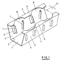
- the trough shown in FIG. 1 for receiving a row of plant pots is folded from sheet metal and has a trough bottom 1, from the two longitudinal edges 2 of which a trough side wall 3 extends upwards.
- the trough has a trapezoidal shape, i.e. the trough side walls 3 diverge upwards.
- a holding flange 5 is directed horizontally inwards from the upper edges 4 of the trough side walls 3.
- the holding flanges 5 consist of the folded edge strips on the upper edges 4 of the trough side walls 3.
- the holding flanges 5 have holding recesses 6 which are arranged at a distance from one another in the longitudinal direction of the trough and are adapted to the shape of the plant pots to be received.
- the trough is intended for receiving frustoconical plant pots; therefore, the holding recesses 6 are each delimited by an arc.
- the holding recesses 6 can also have other shapes to adapt to other pot cross sections and, for example, be rectangular for receiving rectangular, in particular square, plant pots.
- Fig. 1 it is indicated by dash-dotted lines that the holding flanges can also be made as wide, that opposite holding flanges 5 'touch or even overlap, so that the trough is closed at the top in the area between the plant pots.
- the trough can also be made of other materials, for example plastic.
- two holding tabs 7 Seen in the longitudinal direction of the trough, two holding tabs 7 are punched out on both sides of each holding recess 6 from the associated trough side wall 3 and folded over into the inside of the trough. These holding tabs serve to additionally hold the section of the plant pot received, which lies below the holding flanges 5, in order to avoid even a slight tilting in the longitudinal direction of the trough.
- the punched openings 8 formed by punching out the holding tabs 7 are spaced above the trough bottom 1, so that the water flowing along the trough bottom 1 cannot escape through the punched openings.
- troughs which are also referred to as cultivation channels, are usually grouped together on frames (not shown). Several troughs then stand on this frame at a more or less close distance or immediately next to one another.
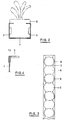
- FIGS. 2 and 3 differs from the previously described embodiment primarily in that the trough side walls 3 are arranged vertically. This trough is primarily intended for receiving plant pots 9 with vertical walls.
- the holding recesses 6 are arranged at a distance from one another in the longitudinal direction of the trough which is smaller than the smallest possible distance between adjacent plant pots 9.
- the distance between the holding recesses 6 is chosen so that it is one integer fraction of the largest intended distance of the plant pots corresponds.
- This arrangement gives the possibility of choosing the mutual spacing of neighboring plant pots 9 differently depending on the size of the plant species cultivated therein, without having to provide different troughs for this.
- a plant pot 9 is arranged in every second holding recess 6.
- a plant pot 9 can be accommodated in every third holding recess 6, for example.
- the holding recesses 6 shown or the sections of the holding flanges 5 remaining between them they can also be designed such that tooth-like or tooth-like projections remain which hold the plant pots and engage between the adjacent plant pots.
- Fig. 4 shows the upper edge of a trough side wall 3, on which a plastic rail 10 is attached, which forms the horizontal retaining flange 5.
- the plastic rail 10 can also be attached to the trough side wall 3 in a different manner, for example clamped, glued or molded.
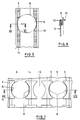
- the Retaining flange 5 is formed by a series of horizontal flexible fingers or knobs 11. When inserting a plant pot 9, these knobs 11 are partially bent downward, as shown in FIGS. 5 and 6, so that there is the holding recess 6 for the plant pot 9.
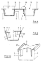
- each trough is formed by a channel 12 of a trapezoidal sheet 13 known per se.
- the trapezoidal sheet 13 thus has a plurality of troughs lying side by side for receiving plant pots 9.
- the holding flanges 5, which hold the plant pots 9, consist of profiled sheet metal tabs 14 which are arranged at a distance from one another and which are punched out of the horizontal flange surfaces 15 lying between the channels 12 on the upper side of the trapezoidal sheet 13 and bent by 180 ° over the respectively adjacent channel 12 are. This bending direction is indicated by the arrow 16 in FIG. 8.
- retaining tabs 7 can be punched out of the trough side walls 3, as has already been described in connection with FIG. 1.
- FIG. 9 shows two embodiments of holders 17 and 18 which can be plugged onto the trough side walls 3 and which are injection-molded, for example, from plastic.
- the holder 17 or 18 has a section 19 which is reversely U-shaped in cross section and which engages over the upper edge of the trough side wall 3. From this section 19 a part forming the holding flange 5 extends horizontally inwards and is shaped in such a way that it holds the plant pot used.
- this horizontal holding flange extends over the upper edge of the associated trough side wall 3 and is connected to an edge strip 20 which is angled downwards.
- the holder 17 or 18 can be plugged into the trough side wall 3 at any point so that the desired mutual spacing of the plant pots can be determined. It is not possible, as shown in the earlier exemplary embodiments, to punch holding tabs 7 out of the trough side walls 3. Instead, retaining tabs 7 'are molded onto the holders 17 and 18, which are preferably injection-molded from plastic. These holding tabs 7 'extend downward from the holding flanges 5 and support the received plant pot in order to prevent tipping in the longitudinal direction of the trough.
- FIGS. 9 and 10 in particular the trough shape with a trapezoidal cross section according to FIG. 9, have the advantage that the troughs to facilitate the Transport can be stacked because the holding flanges 5 do not interfere.
- the use of individual holders 17, 18 and 22 makes it easier to adapt to different shapes and sizes of plant pots and to select the respective spacing between the plant pots in a simple manner.
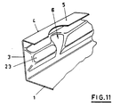
- FIG. 11 shows a spatial representation of a section of a trough according to a further modified embodiment.
- the two trough side walls 3 (only one of which is shown) are provided with inwardly projecting molded projections 23.
- the shaped projections 23 are formed by deep drawing from the trough side wall 3, which thereby receives a special stiffening.
- Each plant pot is held by the four adjacent molded projections 23, namely two molded projections 23 projecting from each trough side wall 3.
- the holding flanges 5 in addition to the molded projections 23, are folded over from one another by the upper edges 4 of the trough side walls 3.
- the holding recess 6 for a plant pot is formed both by the holding tabs 5 and by the molded projections 23.
- the holding flanges 5 can also be dispensed with if the molded projections 23 are made sufficiently high to hold the plant pot.
- the holding tabs 7 and 7 ' can be made so high that they provide sufficient lateral support for the plant pots, so that the holding tabs 5 can also be dispensed with there.
Landscapes
- Life Sciences & Earth Sciences (AREA)
- Environmental Sciences (AREA)
- Cultivation Receptacles Or Flower-Pots, Or Pots For Seedlings (AREA)
Abstract
Claims (16)
- Bac pour pots de fleurs comportant un fond (1) à partir des deux bords latéraux (2) duquel s'étendent vers le haut des parois latérales (3) entre lesquelles peuvent être reçus une série de pots de fleurs, qui peuvent s'appuyer sur le fond (1) du bac, caractérisé en ce que des éléments d'appui (5, 7, 7', 23) font saillie en regard l'un de l'autre des deux parois latérales (3) du bac pour maintenir les pots de fleurs à distance l'un de l'autre dans la direction longitudinale du bac.
- Bac selon la revendication 1, caractérisé en ce que les éléments d'appui sont des ailes d'appui (5), qui font saillie des bords supérieurs (4) des deux parois latérales (3) du bac en regard et dans lesquelles des évidements d'appui (6) agencés à distance l'un de l'autre dans la direction longitudinale du bac sont formés pour recevoir les pots de fleurs.
- Bac selon la revendication 2, caractérisé en ce que les ailes d'appui (5) sont formées par des bandes marginales repliées à l'horizontale sur les bords supérieurs (4) des parois latérales (3) du bac.
- Bac selon la revendication 1, caractérisé en ce que l'on estampe a titre d'éléments d'appui dans les parois latérales (3) du bac des pattes d'appui (7) et on les replie à l'intérieur du bac, et l'ouverture estampée (8) ainsi formée est à une certaine distance du fond (1) du bac.
- Bac selon la revendication 1, caractérisé en ce que les parois latérales (3) du bac sont dotées de saillies moulées (23) dépassant vers l'intérieur pour former des éléments d'appui.
- Bac selon la revendication 5, caractérisé en ce que les saillies moulées (23) sont embouties.
- Bac selon la revendication 2, caractérisé en ce que les ailes d'appui (5) se présentent sous la forme de profilés (10) qui sont fixés aux bords supérieurs des parois latérales (3) du bac.
- Bac selon la revendication 7, caractérisé en ce que les profilés (10) formant les ailes d'appui (5) sont enfichés sur les bords supérieurs des parois latérales (3) du bac.
- Bac selon la revendication 7 ou 8, caractérisé en ce que les profilés (10) sont constitués de matière plastique.
- Bac selon la revendication 2, caractérisé en ce que l'écart entre évidements d'appui voisins (6) est une fraction entière de l'écart le plus grand prévu entre les pots de fleurs (9).
- Bac selon la revendication 2, caractérisé en ce qu'il est formé respectivement d'une gouttière (12) de tôle à section trapézoïdale (13) et les ailes d'appui (5) sont constituées de pattes de tôle (14) profilées et agencées à distance l'une de l'autre, qui sont estampées dans les faces (15) des ailes horizontales supérieures de la tôle à section trapézoïdale (13) qui se raccordent des deux côtés à la gouttière (12) et sont repliées de 180° au-dessus de la gouttière (12).
- Bac selon la revendication 7, caractérisé en ce que les ailes d'appui (5) sont constituées respectivement d'une série de nopes flexibles horizontales (11) qui peuvent être repliées par les pots de fleurs utilisés (9).
- Bac selon la revendication 12, caractérisé en ce que les ailes d'appui (5') s'étendant l'une en regard de l'autre des parois latérales (3) du bac viennent en contact ou se chevauchent.
- Bac selon la revendication 2, caractérisé en ce que les ailes d'appui (5) sont formées par des parties s'étendant horizontalement de supports (17, 18, 22) enfichés sur les parois latérales (3) du bac.
- Bac selon la revendication 14, caractérisé en ce que des pattes d'appui (7') faisant saillie vers le bas sont moulées sur les supports (17, 18, 22).
- Bac selon la revendication 14, caractérisé en ce que les ailes d'appui (5) sont conformées en barrettes sur l'un des supports (22) pontant les parois latérales voisines (3) du bac.
Applications Claiming Priority (2)
| Application Number | Priority Date | Filing Date | Title |
|---|---|---|---|
| DE3839664A DE3839664A1 (de) | 1988-11-24 | 1988-11-24 | Trog fuer pflanzentoepfe |
| DE3839664 | 1988-11-24 |
Publications (2)
| Publication Number | Publication Date |
|---|---|
| EP0445197A1 EP0445197A1 (fr) | 1991-09-11 |
| EP0445197B1 true EP0445197B1 (fr) | 1993-10-06 |
Family
ID=6367801
Family Applications (1)
| Application Number | Title | Priority Date | Filing Date |
|---|---|---|---|
| EP90900126A Expired - Lifetime EP0445197B1 (fr) | 1988-11-24 | 1989-11-21 | Bac pour pots de fleurs |
Country Status (4)
| Country | Link |
|---|---|
| EP (1) | EP0445197B1 (fr) |
| DE (2) | DE3839664A1 (fr) |
| DK (1) | DK97691A (fr) |
| WO (1) | WO1990005447A1 (fr) |
Cited By (1)
| Publication number | Priority date | Publication date | Assignee | Title |
|---|---|---|---|---|
| KR101403478B1 (ko) | 2013-06-17 | 2014-06-03 | 이상봉 | 높낮이 조절식 난간용 화분 받침대 |
Families Citing this family (9)
| Publication number | Priority date | Publication date | Assignee | Title |
|---|---|---|---|---|
| DE4026105C1 (en) * | 1990-05-10 | 1991-06-20 | Ralf Ruediger Fischer | Carrier for plant culture troughs - has rails with sprung fish plates to retain troughs for plants |
| US5111955A (en) * | 1990-08-16 | 1992-05-12 | Halliburton Company | Non-metallic acid hatch |
| DE9014844U1 (de) * | 1990-10-26 | 1991-01-10 | Fischer, Bernd, 6054 Rodgau | Trog für Pflanzentöpfe |
| DE4407743C2 (de) * | 1994-02-05 | 1995-11-16 | Erich Blattert | Vorrichtung zum Aufnehmen mehrerer bepflanzter Töpfe |
| DE9409269U1 (de) * | 1994-06-08 | 1994-09-29 | Pfeiffer, Harald, 52379 Langerwehe | Einrichtung für die Aufnahme eines Kunststoffeinsatzes zur Aufnahme von Pflanzenerde |
| US5673511A (en) * | 1995-12-28 | 1997-10-07 | Holtkamp Greenhouses, Inc. | Plant stand with self-watering trays |
| US9227776B2 (en) | 2012-12-16 | 2016-01-05 | Karl Ronald Chapel | Tray for transporting horticultural containers |
| US9338948B2 (en) | 2012-12-18 | 2016-05-17 | East Jordan Plastics, Inc. | Plant pot holder tray |
| DE102019130537A1 (de) | 2019-11-12 | 2021-05-12 | Jochen Friedrich Haubner | Automat zum Verkauf von Pflanzen, insbesondere Nutz- und/oder Zierpflanzen wie Salate, Gemüse, Blumen und dergleichen sowie Kulturrinne zur Aufnahme solcher Pflanzen |
Citations (1)
| Publication number | Priority date | Publication date | Assignee | Title |
|---|---|---|---|---|
| DE2732982A1 (de) * | 1976-07-21 | 1978-02-02 | Lymington | Vorrichtung zum verschieben bzw. versetzen von pflanzenbehaeltern laengs eines gewaechshauses o.dgl. |
Family Cites Families (5)
| Publication number | Priority date | Publication date | Assignee | Title |
|---|---|---|---|---|
| FR1346075A (fr) * | 1963-01-29 | 1963-12-13 | Dispositif pour la culture de jeunes plants | |
| FR2124192B1 (fr) * | 1971-02-05 | 1974-02-15 | Ferrand Marcel | |
| BE779292A (fr) * | 1971-02-17 | 1972-05-30 | Schapira Augusto | Recipient, de preference en matiere synthetique, propre a l'usage de pot de fleur de formes et dimensions differentes |
| FR2442005A1 (fr) * | 1978-11-22 | 1980-06-20 | Doftoras Sarah | Dispositif destine a donner a un pot de fleurs une plus grande stabilite |
| US4476651A (en) * | 1983-01-27 | 1984-10-16 | Geoffrey Drury | Apparatus and method for transporting growing plants |
-
1988
- 1988-11-24 DE DE3839664A patent/DE3839664A1/de not_active Withdrawn
-
1989
- 1989-11-21 DE DE90900126T patent/DE58905856D1/de not_active Expired - Fee Related
- 1989-11-21 EP EP90900126A patent/EP0445197B1/fr not_active Expired - Lifetime
- 1989-11-21 WO PCT/EP1989/001411 patent/WO1990005447A1/fr not_active Ceased
-
1991
- 1991-05-23 DK DK097691A patent/DK97691A/da not_active Application Discontinuation
Patent Citations (1)
| Publication number | Priority date | Publication date | Assignee | Title |
|---|---|---|---|---|
| DE2732982A1 (de) * | 1976-07-21 | 1978-02-02 | Lymington | Vorrichtung zum verschieben bzw. versetzen von pflanzenbehaeltern laengs eines gewaechshauses o.dgl. |
Cited By (1)
| Publication number | Priority date | Publication date | Assignee | Title |
|---|---|---|---|---|
| KR101403478B1 (ko) | 2013-06-17 | 2014-06-03 | 이상봉 | 높낮이 조절식 난간용 화분 받침대 |
Also Published As
| Publication number | Publication date |
|---|---|
| DE3839664A1 (de) | 1990-05-31 |
| DK97691D0 (da) | 1991-05-23 |
| DK97691A (da) | 1991-05-23 |
| WO1990005447A1 (fr) | 1990-05-31 |
| DE58905856D1 (de) | 1993-11-11 |
| EP0445197A1 (fr) | 1991-09-11 |
Similar Documents
| Publication | Publication Date | Title |
|---|---|---|
| DE69216402T2 (de) | Gehaüse zum helfen der bewässerung von pflanzen | |
| EP2291070B1 (fr) | Pot pour plantes | |
| DE3403165A1 (de) | Vorrichtung zur bodenstabilisierung im wasserbau | |
| EP0374898B1 (fr) | Table de plantes | |
| WO1990005447A1 (fr) | Bac pour pots de fleurs | |
| DE2945103A1 (de) | Fluessigkeitsverteiler fuer eine gegenstromkolonne | |
| AT393210B (de) | Einlage fuer ein bett in form eines lattenrostes | |
| DE10211723C1 (de) | Kulturplatte zum Bewurzeln von Jungpflanzen | |
| EP1426521A2 (fr) | Façade pour murs | |
| DE2119585A1 (de) | Verbindungsmittel für Drahtgestelle | |
| EP0988783B1 (fr) | Bac de culture pour l'enracinement de plantules | |
| DE2617890A1 (de) | Vorrichtung zum ableiten von kondenswasser von der unterseite eines daches oder einer decke | |
| DE4026105C1 (en) | Carrier for plant culture troughs - has rails with sprung fish plates to retain troughs for plants | |
| DE2716289C3 (de) | Führungsschiene zum Anbringen von Schubfächern an Drahtgitterwänden | |
| DE3524923A1 (de) | Umzaeunung | |
| DE3816127A1 (de) | Bepflanzbare laermschutzwand | |
| DE202020004181U1 (de) | Set aus einer Anzuchtplatte für Pflanzen und einer Trägerplatte | |
| DE102004063846B4 (de) | Grünwandkorb | |
| DE3905896A1 (de) | Klammer zur halterung von verkleidungsplatten an fassadenwaenden | |
| EP0482463B1 (fr) | Auge pour pots de plantes | |
| EP4623672A1 (fr) | Système hydroponique | |
| DE29507247U1 (de) | Anstautisch für Gewächshäuser aus einzelnen miteinander verbindbaren Wannenteilen | |
| DE2022156A1 (de) | Selbsttaetig einstellbare Deckenleiste fuer Schraenke mit Raumhoehe | |
| DE102024102333A1 (de) | Fassadenrinne | |
| DE29817249U1 (de) | Kulturplatte zum Bewurzeln von Jungpflanzen |
Legal Events
| Date | Code | Title | Description |
|---|---|---|---|
| PUAI | Public reference made under article 153(3) epc to a published international application that has entered the european phase |
Free format text: ORIGINAL CODE: 0009012 |
|
| 17P | Request for examination filed |
Effective date: 19910315 |
|
| AK | Designated contracting states |
Kind code of ref document: A1 Designated state(s): BE CH DE ES FR GB IT LI NL |
|
| 17Q | First examination report despatched |
Effective date: 19930216 |
|
| GRAA | (expected) grant |
Free format text: ORIGINAL CODE: 0009210 |
|
| AK | Designated contracting states |
Kind code of ref document: B1 Designated state(s): BE CH DE ES FR GB IT LI NL |
|
| PG25 | Lapsed in a contracting state [announced via postgrant information from national office to epo] |
Ref country code: IT Free format text: LAPSE BECAUSE OF FAILURE TO SUBMIT A TRANSLATION OF THE DESCRIPTION OR TO PAY THE FEE WITHIN THE PRE;WARNING: LAPSES OF ITALIAN PATENTS WITH EFFECTIVE DATE BEFORE 2007 MAY HAVE OCCURRED AT ANY TIME BEFORE 2007. THE CORRECT EFFECTIVE DATE MAY BE DIFFERENT FROM THE ONE RECORDED.SCRIBED TIME-LIMIT Effective date: 19931006 Ref country code: GB Effective date: 19931006 Ref country code: FR Effective date: 19931006 Ref country code: BE Effective date: 19931006 Ref country code: ES Free format text: THE PATENT HAS BEEN ANNULLED BY A DECISION OF A NATIONAL AUTHORITY Effective date: 19931006 |
|
| REF | Corresponds to: |
Ref document number: 58905856 Country of ref document: DE Date of ref document: 19931111 |
|
| PG25 | Lapsed in a contracting state [announced via postgrant information from national office to epo] |
Ref country code: LI Effective date: 19931130 Ref country code: CH Effective date: 19931130 |
|
| EN | Fr: translation not filed | ||
| GBV | Gb: ep patent (uk) treated as always having been void in accordance with gb section 77(7)/1977 [no translation filed] |
Effective date: 19931006 |
|
| REG | Reference to a national code |
Ref country code: CH Ref legal event code: PL |
|
| PLBE | No opposition filed within time limit |
Free format text: ORIGINAL CODE: 0009261 |
|
| STAA | Information on the status of an ep patent application or granted ep patent |
Free format text: STATUS: NO OPPOSITION FILED WITHIN TIME LIMIT |
|
| 26N | No opposition filed | ||
| PGFP | Annual fee paid to national office [announced via postgrant information from national office to epo] |
Ref country code: DE Payment date: 19991119 Year of fee payment: 11 |
|
| PGFP | Annual fee paid to national office [announced via postgrant information from national office to epo] |
Ref country code: NL Payment date: 19991130 Year of fee payment: 11 |
|
| PG25 | Lapsed in a contracting state [announced via postgrant information from national office to epo] |
Ref country code: NL Free format text: LAPSE BECAUSE OF NON-PAYMENT OF DUE FEES Effective date: 20010601 |
|
| NLV4 | Nl: lapsed or anulled due to non-payment of the annual fee |
Effective date: 20010601 |
|
| PG25 | Lapsed in a contracting state [announced via postgrant information from national office to epo] |
Ref country code: DE Free format text: LAPSE BECAUSE OF NON-PAYMENT OF DUE FEES Effective date: 20010801 |