EP0445290A1 - Adaptives datenverschlüsselungs/entschlüsselungsgerät und datenübertragungssystem unter verwendung dieses gerätes - Google Patents
Adaptives datenverschlüsselungs/entschlüsselungsgerät und datenübertragungssystem unter verwendung dieses gerätes Download PDFInfo
- Publication number
- EP0445290A1 EP0445290A1 EP89908864A EP89908864A EP0445290A1 EP 0445290 A1 EP0445290 A1 EP 0445290A1 EP 89908864 A EP89908864 A EP 89908864A EP 89908864 A EP89908864 A EP 89908864A EP 0445290 A1 EP0445290 A1 EP 0445290A1
- Authority
- EP
- European Patent Office
- Prior art keywords
- data
- transmission line
- switching means
- ciphering
- transmitting device
- Prior art date
- Legal status (The legal status is an assumption and is not a legal conclusion. Google has not performed a legal analysis and makes no representation as to the accuracy of the status listed.)
- Granted
Links
Images



Classifications
-
- H—ELECTRICITY
- H04—ELECTRIC COMMUNICATION TECHNIQUE
- H04L—TRANSMISSION OF DIGITAL INFORMATION, e.g. TELEGRAPHIC COMMUNICATION
- H04L9/00—Cryptographic mechanisms or cryptographic arrangements for secret or secure communications; Network security protocols
- H04L9/06—Cryptographic mechanisms or cryptographic arrangements for secret or secure communications; Network security protocols the encryption apparatus using shift registers or memories for block-wise or stream coding, e.g. DES systems or RC4; Hash functions; Pseudorandom sequence generators
-
- H—ELECTRICITY
- H04—ELECTRIC COMMUNICATION TECHNIQUE
- H04L—TRANSMISSION OF DIGITAL INFORMATION, e.g. TELEGRAPHIC COMMUNICATION
- H04L9/00—Cryptographic mechanisms or cryptographic arrangements for secret or secure communications; Network security protocols
-
- H—ELECTRICITY
- H04—ELECTRIC COMMUNICATION TECHNIQUE
- H04L—TRANSMISSION OF DIGITAL INFORMATION, e.g. TELEGRAPHIC COMMUNICATION
- H04L9/00—Cryptographic mechanisms or cryptographic arrangements for secret or secure communications; Network security protocols
- H04L9/08—Key distribution or management, e.g. generation, sharing or updating, of cryptographic keys or passwords
- H04L9/0816—Key establishment, i.e. cryptographic processes or cryptographic protocols whereby a shared secret becomes available to two or more parties, for subsequent use
- H04L9/0819—Key transport or distribution, i.e. key establishment techniques where one party creates or otherwise obtains a secret value, and securely transfers it to the other(s)
- H04L9/0827—Key transport or distribution, i.e. key establishment techniques where one party creates or otherwise obtains a secret value, and securely transfers it to the other(s) involving distinctive intermediate devices or communication paths
-
- Y—GENERAL TAGGING OF NEW TECHNOLOGICAL DEVELOPMENTS; GENERAL TAGGING OF CROSS-SECTIONAL TECHNOLOGIES SPANNING OVER SEVERAL SECTIONS OF THE IPC; TECHNICAL SUBJECTS COVERED BY FORMER USPC CROSS-REFERENCE ART COLLECTIONS [XRACs] AND DIGESTS
- Y04—INFORMATION OR COMMUNICATION TECHNOLOGIES HAVING AN IMPACT ON OTHER TECHNOLOGY AREAS
- Y04S—SYSTEMS INTEGRATING TECHNOLOGIES RELATED TO POWER NETWORK OPERATION, COMMUNICATION OR INFORMATION TECHNOLOGIES FOR IMPROVING THE ELECTRICAL POWER GENERATION, TRANSMISSION, DISTRIBUTION, MANAGEMENT OR USAGE, i.e. SMART GRIDS
- Y04S40/00—Systems for electrical power generation, transmission, distribution or end-user application management characterised by the use of communication or information technologies, or communication or information technology specific aspects supporting them
- Y04S40/20—Information technology specific aspects, e.g. CAD, simulation, modelling, system security
Definitions
- the present invention relates to adaptive data ciphering / deciphering apparatuses and a data communication system using these adaptive data ciphering / deciphering apparatuses.
- the system according to the present invention is used, for example, for a facsimile communication in which data is transmitted in the form of ciphered data.
- a data transmitting device such as a facsimile device is able to data-communicate with a destination facsimile device through a telephone transmission line.
- LAN local area network
- a ciphering / deciphering means has been proposed in which a secret key system, such as the data encryption standard (DES) system, and the public key system, has been used.
- DES data encryption standard
- the secret key system since it is necessary to transmit a ciphered secret key from a transmitting station to a receiving station, there is a problem that if the ciphered secret key is obtained by a third party by wire tapping the transmission line, the ciphered data can be easily deciphered by the third party.
- An object of the present invention is to provide an improved data communication system using either a public transmission line or a local transmission network such as a local area network in which the secrecy of communication is secured, the adaptation of the proposed apparatus is possible both for an existing communication system and a new system to be constructed, the proposed apparatus allows flexibility of operations, the cost of construction of the proposed apparatus is not expensive, and protection against the wire tapping of the transmission line is effectively achieved.
- Another object of the present invention is to provide a data ciphering apparatus and a data deciphering apparatus suitable for the above aimed improved data communication system.
- an apparatus for ciphering data for use in a data communication system including: switching means adapted to be connected between a data transmitting device and a transmission line for switching the connection between the data transmitting device and the transmission line to enable an insertion of the ciphering apparatus between the data transmitting device and the transmission line; line condition detector means connected with the switching means for detecting a call from the data transmitting device; control code monitor means connected with the switching means for monitoring communication control codes from the data transmitting means; scramble means connected with the switching means for ciphering data transmitted from the data transmitting device after the detection of the communication control codes by the control code monitor means; and drive control means, connected with the switching means and associated with the switching means, the line condition detector means, the control code monitor means, and the scrambling means, for supplying the transmission line through the switching means with ciphered data of the data from the data transmitting device.
- an apparatus for deciphering ciphered data for use in a data communication system including: switching means adapted to be connected between a transmission line and a data receiving device for switching the connection between the transmission line and the data receiving device to enable an insertion of the deciphering apparatus between the transmission line and the data receiving device; line condition detector means connected with the switching means for detecting a call transmitted through the transmission line; control code monitor means connected with the switching means for monitoring communication control codes through the transmission line; descramble means connected with the switching means for deciphering ciphered data transmitted through the transmission line after the detection of the communication control codes by the control code monitor means; and drive control means, connected with the switching means and associated with the switching means, the line condition detector means, the control code monitor means, and the descrambling means, for receiving data and supplying the data receiving device through the switching means with deciphered data of received data transmitted through the transmission line.
- a data communication system adaptable to a ciphered data communication including: a data transmission line for transmitting ciphered or non-ciphered data between a data transmitting device and a data receiving device; a data transmitting device for transmitting data; a data receiving device for receiving data transmitted through the data transmitting device; a data ciphering apparatus on the side of the data transmitting device; and a data deciphering apparatus on the side of the data receiving device;
- the data ciphering device comprising: switching means between the data transmitting device and the data transmission line for switching the connection between the data transmitting device and the transmission line to enable an insertion of the ciphering apparatus between the data transmitting device and the transmission line; line condition detector means connected with the switching means for detecting a call from the data transmitting device; control code monitor means connected with the switching means for monitoring communication control codes from the data transmitting means; scrambling means connected with the switching means for ciphering the data transmitted from the data transmitting device after the detection of the communication
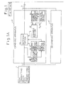
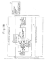
- FIG. 1 A data communication system using data ciphering/deciphering apparatuses according to an embodiment of the present invention is shown in Fig. 1.
- a data ciphering apparatus and a data deciphering apparatus are applied to a facsimile communication system as a data communication system in which a facsimile transmitter as a data transmitting device 1 and a facsimile receiver as a data receiving device 2 are used and the data transmission and receipt are carried out through the telephone transmission line as a transmission line 3.
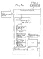
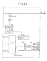
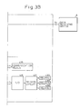
- the structure of the data ciphering apparatus is shown in Fig. 2, and the structure of the data deciphering apparatus is shown in Fig. 3.
- the data ciphering apparatus (facsimile scramble adapter apparatus) 2 is arranged between the data transmitting device 1 and the telephone transmission line 3.
- the data deciphering apparatus (facsimile descramble adapter apparatus) 4 is arranged between the telephone transmission line 3 and the data receiving device 5.
- These data ciphering apparatus and the data deciphering apparatus are adapted to be connected with the existing facsimile communication system through the terminals T1, T2, T3, and T4. These data ciphering apparatus and the data deciphering apparatus are able to be disconnected from this existing facsimile communication system.
- a "one-to-one" communication system is shown in Fig. 1. It should be noted, however, generally an “n-to-n” communication system is possible.
- a parallel data ciphering apparatus and data deciphering apparatus or integrated data ciphering/deciphering apparatus are arranged between the telephone transmission line and the data transmitting device or the data receiving device.
- the explanations are given for the calling side and the called side separately.
- the data ciphering apparatus 2 includes a key code input device 2F of the ten-key type, and relay contacts 211, 212, and 214 and a capacitor 213 as a switching portion 2A.
- These relay contacts 211, 212, and 214 are relay contacts of relay (3), relay (2), and relay (1) driven by a trigger circuit 237.
- the capacitor 213 is for cutting of the direct current.
- the data ciphering apparatus 2 also includes a bell signal detector circuit 221, and an off-hook signal detector circuit 222 as the line condition detector portion 2B and a central processor unit CPU 234 which will be explained later.
- the data ciphering apparatus 2 further includes a carrier detection circuit 231, asynchronous communication modules 232 and 235, an input/output interface 233 and 236, a trigger circuit 237, a central processor unit CPU 234, insulation transformers 281 and 283, 2 line/4 line conversion circuit 282, 4 line/2 line conversion circuit 284, and MODEMs 29 and 285, as the control code monitor portion 2C, the drive control portion 2D, the random number generator portion 2G, and the ciphering means (scramble portion) 2E.
- the data deciphering apparatus 4 has a structure similar to that of the data ciphering apparatus 2, except that a deciphering means is provided in place of the ciphering means in the data ciphering apparatus and no random number generator portion is provided.
- keys for ciphering two kinds of keys are used, that is, an open key (public key) and a confidential key (secret key).
- a public key and a secret key constitute a pair of keys.
- the secret key is known only by the person to whom the secret key belongs.
- the ciphered data ciphered by a public key can be deciphered only by the secret key with which the public key constitutes a pair. Accordingly, by using the keys of this key system, a ciphered data transmitted from a specific transmitting party can be deciphered only by a designated specific receiving party, so that the secret ensuring ability (security) of communication is enhanced.
- the secret key codes of the transmitter party and the receiver party are denoted as T s and R s
- the public key codes of the transmitter party and the receiver party are represented as T p and R p
- Each of these secret key codes and public key codes is represented by a predetermined binary number.
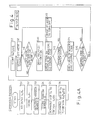
- the transmitting party informs the receiving party in advance of a transmission of a data, by telephone or the like, then, the transmitter party inputs its own secret key code T s and the public key code R p of the receiving party by the key code input device 2F (S1).
- the input secret key code T s and public code R p are stored temporarily in a random access memory RAM (not shown) (S2).
- the receiving party inputs its own secret key code R s with which the public key code R p constitutes a pair and the public key code T p of the transmitting party with which the secret key code T s constitutes a pair (S31).
- the input secret key code R s and public key code T p are stored temporarily in a random access memory RAM (not shown) (S32).
- the random number generator 2G is operated under the control of the CPU 234 to generate a random number D in response to the keys T s and R p supplied from the key code input device 2F.
- the random number D is a predetermined sequence of numerals chosen from 0 to 9.
- the generated random number D which is used as a ciphering key for the data is stored temporarily in a random access memory RAM (not shown) (S3, S4).
- the random number D is ciphered by the secret key code T s .
- the code D ciphered by T s is expressed as T s (D).
- the ciphered code T s (D) is then ciphered by the public key code R p .
- the code T s (D) ciphered by R p is expressed as R p ⁇ T s (D) ⁇ .
- the ciphered code R p ⁇ T s (D) ⁇ is stored temporarily in a random access memory RAM (not shown) (S5, S6, S7).
- off-hook dialing pulse detection circuit 222 in the ciphering apparatus 2 it is detected whether or not an off-hook dialing pulse is received within, for example, 13 sec, and the result of the detection is supplied through the I/O interface 233 to the CPU 234 (S9).
- the bell signal detection circuit 421 in the data deciphering apparatus detects the calling bell signal from the data transmitting device 1 in response to the call processing steps S8 and S9 (S33). After the detection of the calling bell signal, the continuation of the detection of the off-hook state for 1 sec or more is detected by the off-hook dialing pulse detection circuit 422 (S34). When the detection of the off-hook dialing pulse does not continue for 1 sec or more, the process returns to step S33.
- the CPU 234 in the data ciphering apparatus 2 drives the relay (2) through the I/O interface 236 and the driver circuit 237 and the contact 212 of the relay (2) is closed (S10).
- the CPU 434 of the data deciphering apparatus 4 drives the relay (5) through the I/O interface 436, and the trigger circuit 43, and the contact 412 of the relay (5) is closed (S35).
- the monitoring of the control code is carried out by, for example, exchanging at a low frequency an acknowledgement signal between the data ciphering apparatus 2 and the data deciphering apparatus 4, so that an acknowledgement by the counter party is carried out, then the data ciphering apparatus 2 and the data deciphering apparatus 4 carry out the acknowledgement of the same mode or the receivable mode with each other (S12, S37).
- the relay (2) is deenergized through the trigger circuit 237 to open the contact 212 of the relay (2) (S13).
- the relay (5) is driven through the trigger circuit 437 to open the contact 412 of the relay (5) (S38).
- the control code between the data transmitting device 1 and the data receiving device 5 is monitored.
- the control code of the data transmitting device 1 is received through the capacitor 213, the relay contacts 212 and 211, the 2 line/4 line conversion circuit 282, the MODEM 29, the carrier signal detection circuit 231, and the communication module 232, and the received signal is signal-converted to be supplied to the CPU 234.
- the capacitor 213 cuts off the direct current, holds the current of the line, and prevents the hearing of the calling bell sound by the telephone receiver in the data transmitting device in the calling side from becoming impossible.
- the speech transmission approval code (CFR code) is used for a control code of the data transmitting device 1, and this code is monitored by the CPU 234.
- the monitoring of the control code is carried out by the CPU 434 through the transformer 481, 2 line/4 line conversion circuit 482, the MODEM 49, the carrier signal detection circuit 431, and the communication module 432 (S39).
- the relay (2) is driven, and it is checked whether or not the control code is received within a predetermined time such as, for example, 8 sec after the closing of the contact of the relay (2) (S15). If it is checked as not received, the CPU 234 causes the relay (2) to be deenergized to turn off the contact 212 of the relay (2), and the process returns to step S13.
- a predetermined time such as, for example, 8 sec after the closing of the contact of the relay (2) (S15). If it is checked as not received, the CPU 234 causes the relay (2) to be deenergized to turn off the contact 212 of the relay (2), and the process returns to step S13.
- the relay (5) is driven, and it is checked whether or not the control code is received within a predetermined time such as, for example, 8 sec after the closing of the contact 412 of the relay (5) (S40). If it is checked as not received, the CPU 434 causes the relay (5) to be deenergized to turn off the contact 412 of the relay (5), and the process returns to step S38 to again carry out the detection of the dialing.
- a predetermined time such as, for example, 8 sec after the closing of the contact 412 of the relay (5) (S40). If it is checked as not received, the CPU 434 causes the relay (5) to be deenergized to turn off the contact 412 of the relay (5), and the process returns to step S38 to again carry out the detection of the dialing.
- the CPU 234 in the data ciphering apparatus 2 drives the relay (1) and the relay (3) through the I/O interface 236, and causes the trigger circuit 237 to switch the contacts 214 and 211 of the relay (1) and relay (3) to close downwardly the contact 214 and close upwardly the contact 211 (S16), that is, the connection between the data transmitting device 1 and the telephone transmission line 3 is cut off, and a circuit forming the scramble portion 2E constituted by the contact 211 of the relay (3), the transformer 281, 2 line/4 line conversion circuit 282, the MODEM 29, the carrier detection circuit 231, the communication module 232, the CPU 234, the communication module 235, the MODEM 33, the 4 line/2 line conversion circuit 284, the transformer 283, and the contact 214 of the relay (1) is established.
- the CPU 434 in the data deciphering apparatus 4 drives the relay (4) and the relay (6) through the I/O interface 436 and causes the trigger circuit 437 to switch the contacts 414 and 411 of the relay (4) and relay (6) to close downwardly the contact 414 and close upwardly the contact 411 (S39).
- the connection between the telephone transmission line 3 and the data receiving device 5 is cut off, and a circuit forming the descramble portion 4E constituted by the contact 411 of the relay (6), the transformer 481, the 2 line/4 line conversion circuit 482, the MODEM 49, the carrier signal detection circuit 431, the communication module 432, the CPU 434, the communication module 485, the 4 line/2 line conversion circuit 484, the transformer 483, and the contact 414 of the relay (4) is established.
- the ciphering key code temporally stored in the RAM is read, and the read ciphering ciphering key code R p ⁇ T s (D) ⁇ is transmitted to the data deciphering apparatus through the telephone transmission line 3 (S17).
- the above-transmitted ciphering key code is supplied to the CPU 434 through the contact 411 of the relay (6), the transformer 481, the 2 line/4 line conversion circuit 482, the MODEM 49, the carrier signal detection circuit 431, and the communication module 432 (S42).
- the CPU 434 causes the secret key code R s and the public key code T p stored in the RAM to be read.
- the deciphering of R p ⁇ T s (D) ⁇ by the secret key code of the receiving party corresponding to the public key code R p is carried out.
- the deciphered data is expressed as T s (D) (S43).
- non-ciphered data transmitted from the data transmitting device 1 is received through the MODEM 29, the received data is ciphered (scrambled) by random number D under control of the CPU 234, and the thus ciphered data is transmitted to the transmission line 3 through the MODEM 33 (S18, S19).
- the ciphered data transmitted through the transmission line 3 is received by the CPU 434 through the MODEM 49, the received ciphered data is deciphered (descrambled), and the thus deciphered data which is the same as the data which was transmitted from the data transmitting device 1 is supplied to the data receiving device 5 through the MODEM 485 and the contact 414 of the relay (4) (S46, S47).
- the deciphering (descramble) is the reverse operation of the ciphering (scramble).
- the data transmitted from the data transmitting device 1 is reproduced in the data receiving device 5.
- a carrier signal of, for example, 75 ⁇ 20 ms exists between the completion of the transmission of one page of data and the transmission of the next control code.
- the carrier signal is detected by the carrier signal detection circuit 231
- the carrier signal is detected by the carrier signal detection circuit 431.
- the detections of the carrier signal are informed to the CPU 234 and CPU 434 each of which detects the completion of the transmission of one page of data (S20, S48).
- the CPU 234 in the data ciphering apparatus 2 Upon detection of the completion of transmission of one page of data, the CPU 234 in the data ciphering apparatus 2 causes the relay (1) to deenergize to close upwardly the contact 214 of the relay (1) (S21). In a similar manner, the CPU 434 in the data deciphering apparatus 4 causes the relay (4) to deenergize to close upwardly the contact 414 of the relay (4) (S49).
- a circuit constituted by the data transmitting device 1, the telephone transmission line 3, and the data receiving device 5 is established.
- a circuit constituted by the data transmitting device 1, the MODEM 29, and the CPU 234 is established, and in the called side, a circuit constituted by the telephone transmission line 3, the MODEM 49, and the CPU 434 is established.
- the monitoring of the control code between the data transmitting device and the data receiving device becomes possible.
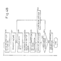
- each of the CPU 234 in the data ciphering apparatus and the CPU 434 in the data deciphering apparatus 4 effects monitoring of whether a multi-page signal, i.e., MPS code, is received or a cut-off instruction instruction signal, i.e., DCN code, is received (S22, S31). If a MPS code is received, the data communication of the next page is successively carried out, and accordingly, in the calling side, the process returns through step S23 to step S18, and in the called side, the process returns through step S41 to step S45.
- MPS code multi-page signal
- DCN code cut-off instruction instruction signal
- the CPU 234 causes the relay (2) and relay (3) to deenergize. Accordingly, the circuits constituting the scramble portion 2E and the control code monitor portion 2C are cut off from the circuit of the data transmitting device 1 and the telephone transmission line 3. However, the line condition detection portion 213 and the drive control portion 2D are able to operate.
- the CPU 434 causes the relay (5) and the relay (6) to deenergize. Accordingly, the circuits constituting the descramble portion 4E and the control code monitor portion 4C are cut off from the circuit of the telephone transmission line 3 and the data receiving device 5. However, the line condition detection portion 413 and the drive control portion 4D are able to operate.
- the communication of the ciphering key codes between the data ciphering apparatus and the data deciphering apparatus is carried out in step S17 and step S42.
- the ciphering key codes may be incorporated with the control codes used in step S11 and S36.
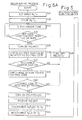
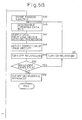
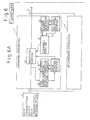
- FIG. 6 A data communication system using data ciphering/deciphering apparatuses according to a modified embodiment of the present invention is shown in Fig. 6 in which the ciphering of a random number D by a ciphering key code Id which is a specific code of the data deciphering apparatus connected between the transmission line 3 and the data receiving device 5, is carried out.
- the structure of the system of Fig. 6 is similar to that of Fig. 1, except that the key code inputting device 4F is replaced by a storage device 4G.
- the storage device 4G stores a ciphering key code Id which is a specific code preliminarily determined for the data deciphering apparatus 4.
- the ciphering key code Id for the data deciphering apparatus 4 is preliminarily made open to the public in correspondence with the data receiving device 5.
- the transmitting party inputs a ciphering key code Id of the receiving party through the key code inputting device 2F (S61).
- the input ciphering key code Id is stored temporarily in a RAM (not shown) (S62).
- the random number generator portion 2G is operated under control of the CPU to generate a random number D (S63).
- the generated random number D which is used for a ciphering key code for the communication data is stored temporarily in a RAM (not shown) (S64).
- the random number D is ciphered by the ciphering key code Id.
- the ciphered random number is expressed as I d (D).
- the ciphered random number I d (D) is stored temporarily in a RAM (not shown).
- the ciphered key code temporarily stored in the RAM is read, and the read ciphered random number key code I d (D) is transmitted to the data deciphering apparatus 4 through the transmission line 3 (Fig. 4, S17).
- the ciphering key code I d (D) is supplied to the CPU 434 through the contact 411 of the relay (6), the transformer 481, the 2 line/4 line conversion circuit 482, the MODEM 49, the carrier signal detection circuit 431, and the communication module 432 (S100).
- the CPU 434 causes the ciphering key code I d preliminarily stored in the RAM (S101) to be read.
- the ciphered random number I d (D) is deciphered by the read ciphering key code I d to obtain the random number D (S102).
- the obtained random number D is temporarily stored in a RAM (S103).
- the circuit constituted by the data transmitting device, the telephone transmission line, and the data receiving device 5 is cut off only when the by-passing is carried out by the scramble portion 2E and the descramble portion in the case of data transmission.
- the above-mentioned circuit is operated in parallel with the data ciphering apparatus 2 and the data deciphering apparatus 4. In this case, the transmission and the reception of the control code is carried out in a similar manner as explained before.
- the data transmitting device 1 and the data receiving device 5 themselves are not affected by such ciphering and deciphering. Therefore, it is possible to apply the data ciphering apparatus 2 and the data deciphering apparatus 4 not only to a new communication system to be constructed, but also to an existing communication system.
- a data deciphering apparatus 4' and a data ciphering apparatus 2' can be arranged in data transmitting/receiving devices 1 and 5, respectively, as shown in broken lines in Fig. 1.
- Fig. 1 and Fig. 6 can be applied not only to "one-to-one" data communication system but also various other data communication systems.
Landscapes
- Engineering & Computer Science (AREA)
- Computer Security & Cryptography (AREA)
- Computer Networks & Wireless Communication (AREA)
- Signal Processing (AREA)
- Facsimile Transmission Control (AREA)
- Communication Control (AREA)
- Small-Scale Networks (AREA)
- Devices For Checking Fares Or Tickets At Control Points (AREA)
Applications Claiming Priority (3)
| Application Number | Priority Date | Filing Date | Title |
|---|---|---|---|
| JP63287639A JPH02134940A (ja) | 1988-11-16 | 1988-11-16 | データ暗号化アダプタ装置、データ復号化アダプタ装置、およびこれらを用いたデータ通信システム |
| JP287639/88 | 1988-11-16 | ||
| PCT/JP1989/000746 WO1990006029A1 (fr) | 1988-11-16 | 1989-07-26 | Appareil adaptatif de chiffrement/dechiffrement de donnees et systeme de communications de donnees utilisant cet appareil |
Publications (3)
| Publication Number | Publication Date |
|---|---|
| EP0445290A1 true EP0445290A1 (de) | 1991-09-11 |
| EP0445290A4 EP0445290A4 (en) | 1993-01-13 |
| EP0445290B1 EP0445290B1 (de) | 1997-03-05 |
Family
ID=17719832
Family Applications (1)
| Application Number | Title | Priority Date | Filing Date |
|---|---|---|---|
| EP89908864A Expired - Lifetime EP0445290B1 (de) | 1988-11-16 | 1989-07-26 | Adaptives datenverschlüsselungs/entschlüsselungsgerät und datenübertragungssystem unter verwendung dieses gerätes |
Country Status (7)
| Country | Link |
|---|---|
| EP (1) | EP0445290B1 (de) |
| JP (1) | JPH02134940A (de) |
| KR (1) | KR940000178B1 (de) |
| AT (1) | ATE149769T1 (de) |
| CA (1) | CA1337997C (de) |
| DE (1) | DE68927831T2 (de) |
| WO (1) | WO1990006029A1 (de) |
Cited By (2)
| Publication number | Priority date | Publication date | Assignee | Title |
|---|---|---|---|---|
| WO1998007254A1 (en) * | 1996-08-09 | 1998-02-19 | University Court Of The University Of Paisley | Device and method for safeguarding data transferred between machines operating within a network |
| US10396816B2 (en) | 2014-12-19 | 2019-08-27 | International Business Machines Corporation | Pad encoding and decoding |
Families Citing this family (6)
| Publication number | Priority date | Publication date | Assignee | Title |
|---|---|---|---|---|
| JPH1011509A (ja) * | 1996-06-26 | 1998-01-16 | Wacom Co Ltd | 電子書類セキュリティシステム、電子押印セキュリティシステムおよび電子署名セキュリティシステム |
| JP2009296190A (ja) * | 2008-06-04 | 2009-12-17 | Panasonic Corp | 秘匿通信方法 |
| US9425825B2 (en) | 2012-05-22 | 2016-08-23 | International Business Machines Corporation | Path encoding and decoding |
| GB2533391A (en) | 2014-12-19 | 2016-06-22 | Ibm | Wall encoding and decoding |
| GB2533392A (en) | 2014-12-19 | 2016-06-22 | Ibm | Path encoding and decoding |
| US9950261B2 (en) | 2016-04-29 | 2018-04-24 | International Business Machines Corporation | Secure data encoding for low-resource remote systems |
Family Cites Families (7)
| Publication number | Priority date | Publication date | Assignee | Title |
|---|---|---|---|---|
| DE1076732B (de) * | 1958-04-24 | 1960-03-03 | Telefunken Gmbh | Anordnung fuer Fernschreibmaschinen mit wahlweise einschaltbarem Verschluesselungszusatz |
| US4091423A (en) * | 1975-03-17 | 1978-05-23 | Datotek, Inc. | Synchronous digital data scrambling system |
| DE3210081C2 (de) * | 1982-03-19 | 1984-12-20 | Siemens AG, 1000 Berlin und 8000 München | Verfahren und Anordnung zum Übertragen von verschlüsselten Texten |
| JPS5944145A (ja) * | 1982-09-06 | 1984-03-12 | Fujitsu Ltd | 暗号通信方式 |
| JPS60105338A (ja) * | 1983-11-12 | 1985-06-10 | Fujitsu Ltd | 回線暗号装置 |
| JPS62216447A (ja) * | 1986-03-17 | 1987-09-24 | Nippon Telegr & Teleph Corp <Ntt> | メツセ−ジ認証通信方式 |
| JP2582356B2 (ja) * | 1986-09-30 | 1997-02-19 | 株式会社東芝 | フアクシミリ通信方式 |
-
1988
- 1988-11-16 JP JP63287639A patent/JPH02134940A/ja active Pending
-
1989
- 1989-07-26 EP EP89908864A patent/EP0445290B1/de not_active Expired - Lifetime
- 1989-07-26 DE DE68927831T patent/DE68927831T2/de not_active Expired - Fee Related
- 1989-07-26 WO PCT/JP1989/000746 patent/WO1990006029A1/ja not_active Ceased
- 1989-07-26 AT AT89908864T patent/ATE149769T1/de not_active IP Right Cessation
- 1989-07-26 KR KR1019900701492A patent/KR940000178B1/ko not_active Expired - Fee Related
- 1989-08-09 CA CA000607846A patent/CA1337997C/en not_active Expired - Fee Related
Cited By (2)
| Publication number | Priority date | Publication date | Assignee | Title |
|---|---|---|---|---|
| WO1998007254A1 (en) * | 1996-08-09 | 1998-02-19 | University Court Of The University Of Paisley | Device and method for safeguarding data transferred between machines operating within a network |
| US10396816B2 (en) | 2014-12-19 | 2019-08-27 | International Business Machines Corporation | Pad encoding and decoding |
Also Published As
| Publication number | Publication date |
|---|---|
| KR940000178B1 (ko) | 1994-01-08 |
| EP0445290A4 (en) | 1993-01-13 |
| JPH02134940A (ja) | 1990-05-23 |
| DE68927831D1 (de) | 1997-04-10 |
| KR900702687A (ko) | 1990-12-08 |
| EP0445290B1 (de) | 1997-03-05 |
| ATE149769T1 (de) | 1997-03-15 |
| DE68927831T2 (de) | 1997-09-25 |
| CA1337997C (en) | 1996-01-23 |
| WO1990006029A1 (fr) | 1990-05-31 |
Similar Documents
| Publication | Publication Date | Title |
|---|---|---|
| US5253293A (en) | Adaptive data ciphering/deciphering apparatuses and data communication system using these apparatuses | |
| US4972479A (en) | Method and apparatus for providing privacy/security in a communication system | |
| KR920002965B1 (ko) | 복수 통화회선 어댑터장치 | |
| KR950007376A (ko) | 안전한 통신 디바이스용 인터페이스 모듈 | |
| CA1337997C (en) | Adaptive data ciphering/deciphering apparatuses and data communication system using these apparatuses | |
| KR100287674B1 (ko) | 통신방법 | |
| JP2650705B2 (ja) | 通信データ暗号化アダプタ装置、通信データ復号化アダプタ装置、およびこれらを用いた通信データ暗号化・復号化方式 | |
| JPH09149023A (ja) | 情報通信処理装置および情報通信処理方法 | |
| JPH0568897B2 (de) | ||
| KR100760804B1 (ko) | 통신망 사용자의 정보 보호 장치 및 그 방법 | |
| JPS6281866A (ja) | 電話機能を有する端末装置 | |
| JP2675320B2 (ja) | 通信装置 | |
| KR100227790B1 (ko) | 팩스 통신에서의 정보 송수신 방법 | |
| JP3103851B2 (ja) | 秘匿通信制御装置 | |
| JP2832449B2 (ja) | 秘匿通信制御装置 | |
| KR860001454B1 (ko) | 다중주파수(mf)형 신호중계방법 및 장치 | |
| JPH0389738A (ja) | 認証機能を備えたデータ暗号化装置及びデータ復号化装置 | |
| JPH05102960A (ja) | 暗号通信方式 | |
| JPH0420318B2 (de) | ||
| JPH08289365A (ja) | 無線電話システムにおける秘話化方法およびそのシステム | |
| JP2000151845A (ja) | ファクシミリ装置 | |
| JPS63232538A (ja) | 秘話通信制御装置 | |
| JPH0622037A (ja) | 暗証番号秘話システム | |
| JPS5944145A (ja) | 暗号通信方式 | |
| JPH02130047A (ja) | 秘匿通信制御装置 |
Legal Events
| Date | Code | Title | Description |
|---|---|---|---|
| PUAI | Public reference made under article 153(3) epc to a published international application that has entered the european phase |
Free format text: ORIGINAL CODE: 0009012 |
|
| 17P | Request for examination filed |
Effective date: 19900625 |
|
| AK | Designated contracting states |
Kind code of ref document: A1 Designated state(s): AT CH DE FR GB IT LI |
|
| A4 | Supplementary search report drawn up and despatched |
Effective date: 19921123 |
|
| AK | Designated contracting states |
Kind code of ref document: A4 Designated state(s): AT CH DE FR GB IT LI |
|
| 17Q | First examination report despatched |
Effective date: 19940811 |
|
| GRAG | Despatch of communication of intention to grant |
Free format text: ORIGINAL CODE: EPIDOS AGRA |
|
| GRAH | Despatch of communication of intention to grant a patent |
Free format text: ORIGINAL CODE: EPIDOS IGRA |
|
| ITF | It: translation for a ep patent filed | ||
| GRAH | Despatch of communication of intention to grant a patent |
Free format text: ORIGINAL CODE: EPIDOS IGRA |
|
| GRAA | (expected) grant |
Free format text: ORIGINAL CODE: 0009210 |
|
| AK | Designated contracting states |
Kind code of ref document: B1 Designated state(s): AT CH DE FR GB IT LI |
|
| REF | Corresponds to: |
Ref document number: 149769 Country of ref document: AT Date of ref document: 19970315 Kind code of ref document: T |
|
| REG | Reference to a national code |
Ref country code: CH Ref legal event code: NV Representative=s name: PATENTANWAELTE SCHAAD, BALASS, MENZL & PARTNER AG Ref country code: CH Ref legal event code: EP |
|
| REF | Corresponds to: |
Ref document number: 68927831 Country of ref document: DE Date of ref document: 19970410 |
|
| ET | Fr: translation filed | ||
| PLBE | No opposition filed within time limit |
Free format text: ORIGINAL CODE: 0009261 |
|
| STAA | Information on the status of an ep patent application or granted ep patent |
Free format text: STATUS: NO OPPOSITION FILED WITHIN TIME LIMIT |
|
| 26N | No opposition filed | ||
| PGFP | Annual fee paid to national office [announced via postgrant information from national office to epo] |
Ref country code: GB Payment date: 19990621 Year of fee payment: 11 |
|
| PGFP | Annual fee paid to national office [announced via postgrant information from national office to epo] |
Ref country code: AT Payment date: 19990708 Year of fee payment: 11 |
|
| PGFP | Annual fee paid to national office [announced via postgrant information from national office to epo] |
Ref country code: CH Payment date: 19990727 Year of fee payment: 11 |
|
| PGFP | Annual fee paid to national office [announced via postgrant information from national office to epo] |
Ref country code: FR Payment date: 19990729 Year of fee payment: 11 |
|
| PGFP | Annual fee paid to national office [announced via postgrant information from national office to epo] |
Ref country code: DE Payment date: 19990924 Year of fee payment: 11 |
|
| PG25 | Lapsed in a contracting state [announced via postgrant information from national office to epo] |
Ref country code: GB Free format text: LAPSE BECAUSE OF NON-PAYMENT OF DUE FEES Effective date: 20000726 Ref country code: AT Free format text: LAPSE BECAUSE OF NON-PAYMENT OF DUE FEES Effective date: 20000726 |
|
| PG25 | Lapsed in a contracting state [announced via postgrant information from national office to epo] |
Ref country code: LI Free format text: LAPSE BECAUSE OF NON-PAYMENT OF DUE FEES Effective date: 20000731 Ref country code: CH Free format text: LAPSE BECAUSE OF NON-PAYMENT OF DUE FEES Effective date: 20000731 |
|
| REG | Reference to a national code |
Ref country code: CH Ref legal event code: PL |
|
| GBPC | Gb: european patent ceased through non-payment of renewal fee |
Effective date: 20000726 |
|
| PG25 | Lapsed in a contracting state [announced via postgrant information from national office to epo] |
Ref country code: FR Free format text: LAPSE BECAUSE OF NON-PAYMENT OF DUE FEES Effective date: 20010330 |
|
| REG | Reference to a national code |
Ref country code: FR Ref legal event code: ST |
|
| PG25 | Lapsed in a contracting state [announced via postgrant information from national office to epo] |
Ref country code: DE Free format text: LAPSE BECAUSE OF NON-PAYMENT OF DUE FEES Effective date: 20010501 |
|
| PG25 | Lapsed in a contracting state [announced via postgrant information from national office to epo] |
Ref country code: IT Free format text: LAPSE BECAUSE OF NON-PAYMENT OF DUE FEES;WARNING: LAPSES OF ITALIAN PATENTS WITH EFFECTIVE DATE BEFORE 2007 MAY HAVE OCCURRED AT ANY TIME BEFORE 2007. THE CORRECT EFFECTIVE DATE MAY BE DIFFERENT FROM THE ONE RECORDED. Effective date: 20050726 |