EP0445332B1 - Dispositif pour surveiller des installations explosives - Google Patents
Dispositif pour surveiller des installations explosives Download PDFInfo
- Publication number
- EP0445332B1 EP0445332B1 EP90104394A EP90104394A EP0445332B1 EP 0445332 B1 EP0445332 B1 EP 0445332B1 EP 90104394 A EP90104394 A EP 90104394A EP 90104394 A EP90104394 A EP 90104394A EP 0445332 B1 EP0445332 B1 EP 0445332B1
- Authority
- EP
- European Patent Office
- Prior art keywords
- sensor
- pressure sensor
- brightness
- pressure
- housing
- Prior art date
- Legal status (The legal status is an assumption and is not a legal conclusion. Google has not performed a legal analysis and makes no representation as to the accuracy of the status listed.)
- Expired - Lifetime
Links
Images
Classifications
-
- G—PHYSICS
- G01—MEASURING; TESTING
- G01L—MEASURING FORCE, STRESS, TORQUE, WORK, MECHANICAL POWER, MECHANICAL EFFICIENCY, OR FLUID PRESSURE
- G01L19/00—Details of, or accessories for, apparatus for measuring steady or quasi-steady pressure of a fluent medium insofar as such details or accessories are not special to particular types of pressure gauges
- G01L19/0092—Pressure sensor associated with other sensors, e.g. for measuring acceleration or temperature
-
- A—HUMAN NECESSITIES
- A62—LIFE-SAVING; FIRE-FIGHTING
- A62C—FIRE-FIGHTING
- A62C37/00—Control of fire-fighting equipment
- A62C37/36—Control of fire-fighting equipment an actuating signal being generated by a sensor separate from an outlet device
-
- G—PHYSICS
- G08—SIGNALLING
- G08B—SIGNALLING SYSTEMS, e.g. PERSONAL CALLING SYSTEMS; ORDER TELEGRAPHS; ALARM SYSTEMS
- G08B17/00—Fire alarms; Alarms responsive to explosion
-
- G—PHYSICS
- G08—SIGNALLING
- G08B—SIGNALLING SYSTEMS, e.g. PERSONAL CALLING SYSTEMS; ORDER TELEGRAPHS; ALARM SYSTEMS
- G08B17/00—Fire alarms; Alarms responsive to explosion
- G08B17/10—Actuation by presence of smoke or gases, e.g. automatic alarm devices for analysing flowing fluid materials by the use of optical means
- G08B17/11—Actuation by presence of smoke or gases, e.g. automatic alarm devices for analysing flowing fluid materials by the use of optical means using an ionisation chamber for detecting smoke or gas
- G08B17/113—Constructional details
Definitions
- the invention relates to a device for monitoring systems at risk of explosion by means of at least one brightness sensor and a pressure sensor which, when predetermined brightness or pressure values are exceeded, trigger explosion protection measures, in particular sealing off the explosion source and supplying extinguishing agent, the two sensors being combined in a common housing and the Pressure sensor facing the room to be monitored.
- the object of the present invention is to improve a device for combined brightness and pressure monitoring of the type described at the outset in such a way that its assembly effort is drastically reduced.
- the brightness sensor is arranged behind the pressure sensor, the pressure sensor being designed as an at least infrared-transmissive plate.
- the invention is based on the surprising finding that the pressure-sensitive plates of the pressure sensors are so translucent with a sufficiently thin wall thickness, or at least so infrared-permeable, that a brightness sensor can be positioned behind them.
- a pressure sensor it is even possible to use ceramic plates which are known per se and which are sufficiently translucent with a wall thickness of approximately 1/2 mm.
- the invention thus offers the advantage that two explosion criteria can be monitored simultaneously with a single installation element.
- the assembly as well as the laying of the corresponding control cables is halved compared to conventional combined monitoring systems.
- an important advantage of the invention is that the brightness sensor is frequently used by the pressure sensor arranged in front of it aggressive media that are circulating in the system to be monitored is shielded. All that is required is to install the pressure sensor tightly in the sensor housing.
- the brightness sensor can be attached directly to the back of the pressure sensor, for example glued on. However, so that there is no impairment in the deformation properties of the pressure sensor, it is advisable to arrange the brightness sensor at a distance behind the pressure sensor and to attach it to the sensor housing, for example.
- the brightness sensor can be designed in a manner known per se as a photocell or pin diode. Its space requirement is then so small that it fits into the conventional housing of the pressure sensors.
- the brightness sensor and the pressure sensor are expediently connected to a common evaluation electronics, which is housed directly in the sensor housing.
- This evaluation electronics is usually a microprocessor, which can optionally be set from the outside to the desired limit values for the brightness or the pressure.
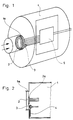
- a screw thread can be arranged on the outside of the projecting collar 1 a in order to screw the housing 1 into a corresponding hole in the system to be monitored.
- a Wheatstone bridge 2 a is attached to measure the deformations that occur under pressure.
- the brightness sensor 3 is located radially offset behind the ceramic plate 2 with respect to the Wheatstone bridge 2 a.
- microprocessor 5 in the housing 1, which processes the signals coming from the two sensors 2 and 3 and emits the corresponding trigger signals when the limit values entered are exceeded.
- the design of such a microprocessor is known per se, which is why not here will be discussed further.
- the pressure sensor 2 is mount the pressure sensor 2 differently in the housing.
- the pressure sensor is so translucent that at least infrared radiation can pass through it and is received by the light sensor 3.
Landscapes
- Business, Economics & Management (AREA)
- Emergency Management (AREA)
- Physics & Mathematics (AREA)
- General Physics & Mathematics (AREA)
- Health & Medical Sciences (AREA)
- Public Health (AREA)
- Chemical & Material Sciences (AREA)
- Analytical Chemistry (AREA)
- Measuring Fluid Pressure (AREA)
Claims (9)
- Dispositif pour la surveillance d'installations sujettes au risque d'explosion, comprenant au moins un capteur de clarté (3) et un capteur de pression (2) qui, en réponse au franchissement de valeurs de clarté et de pression prédéterminées, déclenchent certaines mesures de protection contre l'explosion, en particulier l'isolement du foyer de l'explosion par de cloisons étanches et l'acheminement d'agents d'extinction, les deux capteurs (2, 3) étant combinés dans un boîtier commun (1) et le capteur de pression (2) étant dirigé vers l'espace à surveiller,
caractérisé
en ce que le capteur de clarté (3) est disposé derrière le capteur de pression (2), le capteur de pression (2) étant constitué par une plaquette transparente au moins aux infrarouges. - Dispositif selon la revendication 1,
caractérisé
en ce que le capteur de pression (2) est constitué par une plaque céramique translucide. - Dispositif selon la revendication 1 ou 2,
caractérisé
en ce que le capteur de pression (3) est monté à joint étanche dans le boîtier (1) du capteur. - Dispositif selon une des revendications précédentes,
caractérisé
en ce que le capteur de clarté (3) est fixé sur la face arrière du capteur de pression (2). - Dispositif selon une des revendications précédentes,
caractérisé
en ce que le capteur de clarté (3) est fixé au boîtier (1) du capteur. - Dispositif selon une des revendications précédentes,
caractérisé
en ce que le capteur de clarté (3) est disposé à distance en arrière du capteur de pression (2). - Dispositif selon une des revendications précédentes,
caractérisé
en ce que le capteur de clarté (3) est constitué par une cellule photo-électrique ou une diode épingle. - Dispositif selon une des revendications précédentes,
caractérisé
en ce que les deux capteurs (2, 3) sont raccordés à une électronique d'analyse commune (5) logée dans le boîtier (1) du capteur. - Dispositif selon la revendication 7,
caractérisé
en ce que l'électronique d'analyse (5) est un microprocesseur.
Applications Claiming Priority (1)
| Application Number | Priority Date | Filing Date | Title |
|---|---|---|---|
| DE3830040A DE3830040C2 (de) | 1988-09-03 | 1988-09-03 | Vorrichtung zur Überwachung explosionsgefährdeter Anlagen |
Publications (2)
| Publication Number | Publication Date |
|---|---|
| EP0445332A1 EP0445332A1 (fr) | 1991-09-11 |
| EP0445332B1 true EP0445332B1 (fr) | 1994-06-08 |
Family
ID=6362266
Family Applications (1)
| Application Number | Title | Priority Date | Filing Date |
|---|---|---|---|
| EP90104394A Expired - Lifetime EP0445332B1 (fr) | 1988-09-03 | 1990-03-08 | Dispositif pour surveiller des installations explosives |
Country Status (2)
| Country | Link |
|---|---|
| EP (1) | EP0445332B1 (fr) |
| DE (1) | DE3830040C2 (fr) |
Families Citing this family (1)
| Publication number | Priority date | Publication date | Assignee | Title |
|---|---|---|---|---|
| DE4018998A1 (de) * | 1990-06-13 | 1992-01-02 | Dynisco Geraete Gmbh | Faseroptischer drucksensor |
Family Cites Families (3)
| Publication number | Priority date | Publication date | Assignee | Title |
|---|---|---|---|---|
| DE8416132U1 (de) * | 1984-10-25 | Al Nour, Vaduz | Detektor für Luftdruckänderungen | |
| CH648660A5 (de) * | 1980-12-03 | 1985-03-29 | Cerberus Ag | Strahlungsdetektor fuer einen flammenmelder. |
| US4630684A (en) * | 1984-06-18 | 1986-12-23 | Santa Barbara Research Center | Fire sensing and suppression method and system responsive to optical radiation and mechanical wave energy |
-
1988
- 1988-09-03 DE DE3830040A patent/DE3830040C2/de not_active Expired - Fee Related
-
1990
- 1990-03-08 EP EP90104394A patent/EP0445332B1/fr not_active Expired - Lifetime
Also Published As
| Publication number | Publication date |
|---|---|
| EP0445332A1 (fr) | 1991-09-11 |
| DE3830040A1 (de) | 1990-03-15 |
| DE3830040C2 (de) | 1995-07-06 |
Similar Documents
| Publication | Publication Date | Title |
|---|---|---|
| EP0090872B1 (fr) | Détecteur à haute pression | |
| WO2002095703A2 (fr) | Dispositif et procede de detection de foyers d'incendie ou d'impuretes dans un gaz | |
| DE2425431B2 (de) | Elektrischer Feuer- und Explosionsmelder | |
| DE2833922A1 (de) | Gas- und/oder brandmeldeanlage | |
| EP0016351A1 (fr) | Détecteur de gaz à utiliser dans un milieu menacé par des explosions | |
| EP1912045A1 (fr) | Dispositif de mesure d'un rayonnement ionisant | |
| EP2251846A1 (fr) | Détecteur de flammes | |
| CH677413A5 (fr) | ||
| DE3586774T2 (de) | Feuerdetektions- und -loeschverfahren und -system, empfindlich fuer optische strahlung und mechanische wellenenergie. | |
| EP2306063A2 (fr) | Capteur de sécurité | |
| EP0360004A2 (fr) | Dispositif pour le soulagement de pression d'explosion | |
| EP0445332B1 (fr) | Dispositif pour surveiller des installations explosives | |
| DE2907548C2 (de) | Feuer- und Explosionsunterdrückungsanordnung | |
| DE20103828U1 (de) | Sicherheitseinrichtung zur Überwachung eines Durchgangs | |
| EP2730316B1 (fr) | Dispositif de détection optique pour la détection d'un incendie | |
| DE102008050882A1 (de) | Sensoranordnung | |
| EP1422675B1 (fr) | Dispositif pour découpler des installations chargés de poussières et avec risque d'explosion | |
| RU2593505C1 (ru) | Автоматическое предохранительное устройство систем безопасности в чрезвычайных ситуациях | |
| DE102020206577A1 (de) | Überwachungseinrichtung, insbesondere Umfeldüberwachung, für einen Brandmelder sowie Brandmelder und Zusatzeinrichtung jeweils mit einer derartigen Überwachungseinrichtung | |
| DE102016202585A1 (de) | Modularer Multisensor-Brand- und/oder Funkenmelder | |
| EP3627033B1 (fr) | Dispositif de sécurisation d'une zone à risque d'une installation | |
| DE102021116435A1 (de) | Sensoranordnung mit bündigen oder versenktem Aufbau, insbesondere für ein Wälzlager | |
| EP3862617A1 (fr) | Dispositif de sécurisation d'une zone dangereuse | |
| DE102014110460B3 (de) | Optischer Rauchmelder und Verfahren zur optischen Rauchdetektion | |
| DE10052421C1 (de) | Gekapseltes elektrisches Gerät |
Legal Events
| Date | Code | Title | Description |
|---|---|---|---|
| PUAI | Public reference made under article 153(3) epc to a published international application that has entered the european phase |
Free format text: ORIGINAL CODE: 0009012 |
|
| AK | Designated contracting states |
Kind code of ref document: A1 Designated state(s): DE FR GB IT |
|
| 17P | Request for examination filed |
Effective date: 19910819 |
|
| 17Q | First examination report despatched |
Effective date: 19921223 |
|
| RAP1 | Party data changed (applicant data changed or rights of an application transferred) |
Owner name: IRS INDUSTRIE RATIONALISIERUNGS SYSTEME GMBH |
|
| RBV | Designated contracting states (corrected) |
Designated state(s): FR GB IT |
|
| REG | Reference to a national code |
Ref country code: DE Ref legal event code: 8566 |
|
| GRAA | (expected) grant |
Free format text: ORIGINAL CODE: 0009210 |
|
| ITF | It: translation for a ep patent filed | ||
| AK | Designated contracting states |
Kind code of ref document: B1 Designated state(s): FR GB IT |
|
| GBT | Gb: translation of ep patent filed (gb section 77(6)(a)/1977) |
Effective date: 19940627 |
|
| ET | Fr: translation filed | ||
| PLBE | No opposition filed within time limit |
Free format text: ORIGINAL CODE: 0009261 |
|
| STAA | Information on the status of an ep patent application or granted ep patent |
Free format text: STATUS: NO OPPOSITION FILED WITHIN TIME LIMIT |
|
| 26N | No opposition filed | ||
| REG | Reference to a national code |
Ref country code: GB Ref legal event code: IF02 |
|
| PGFP | Annual fee paid to national office [announced via postgrant information from national office to epo] |
Ref country code: GB Payment date: 20030213 Year of fee payment: 14 |
|
| PGFP | Annual fee paid to national office [announced via postgrant information from national office to epo] |
Ref country code: FR Payment date: 20030318 Year of fee payment: 14 |
|
| PG25 | Lapsed in a contracting state [announced via postgrant information from national office to epo] |
Ref country code: GB Free format text: LAPSE BECAUSE OF NON-PAYMENT OF DUE FEES Effective date: 20040308 |
|
| GBPC | Gb: european patent ceased through non-payment of renewal fee | ||
| PG25 | Lapsed in a contracting state [announced via postgrant information from national office to epo] |
Ref country code: FR Free format text: LAPSE BECAUSE OF NON-PAYMENT OF DUE FEES Effective date: 20041130 |
|
| REG | Reference to a national code |
Ref country code: FR Ref legal event code: ST |
|
| PG25 | Lapsed in a contracting state [announced via postgrant information from national office to epo] |
Ref country code: IT Free format text: LAPSE BECAUSE OF NON-PAYMENT OF DUE FEES;WARNING: LAPSES OF ITALIAN PATENTS WITH EFFECTIVE DATE BEFORE 2007 MAY HAVE OCCURRED AT ANY TIME BEFORE 2007. THE CORRECT EFFECTIVE DATE MAY BE DIFFERENT FROM THE ONE RECORDED. Effective date: 20050308 |