EP0445346B1 - Indikator für das Fehlen einer Batterie - Google Patents
Indikator für das Fehlen einer Batterie Download PDFInfo
- Publication number
- EP0445346B1 EP0445346B1 EP90111466A EP90111466A EP0445346B1 EP 0445346 B1 EP0445346 B1 EP 0445346B1 EP 90111466 A EP90111466 A EP 90111466A EP 90111466 A EP90111466 A EP 90111466A EP 0445346 B1 EP0445346 B1 EP 0445346B1
- Authority
- EP
- European Patent Office
- Prior art keywords
- battery
- base
- cover
- detector
- members
- Prior art date
- Legal status (The legal status is an assumption and is not a legal conclusion. Google has not performed a legal analysis and makes no representation as to the accuracy of the status listed.)
- Expired - Lifetime
Links
Images



Classifications
-
- G—PHYSICS
- G08—SIGNALLING
- G08B—SIGNALLING SYSTEMS, e.g. PERSONAL CALLING SYSTEMS; ORDER TELEGRAPHS; ALARM SYSTEMS
- G08B29/00—Checking or monitoring of signalling or alarm systems; Prevention or correction of operating errors, e.g. preventing unauthorised operation
- G08B29/18—Prevention or correction of operating errors
- G08B29/181—Prevention or correction of operating errors due to failing power supply
-
- G—PHYSICS
- G08—SIGNALLING
- G08B—SIGNALLING SYSTEMS, e.g. PERSONAL CALLING SYSTEMS; ORDER TELEGRAPHS; ALARM SYSTEMS
- G08B17/00—Fire alarms; Alarms responsive to explosion
-
- G—PHYSICS
- G08—SIGNALLING
- G08B—SIGNALLING SYSTEMS, e.g. PERSONAL CALLING SYSTEMS; ORDER TELEGRAPHS; ALARM SYSTEMS
- G08B17/00—Fire alarms; Alarms responsive to explosion
- G08B17/10—Actuation by presence of smoke or gases, e.g. automatic alarm devices for analysing flowing fluid materials by the use of optical means
- G08B17/11—Actuation by presence of smoke or gases, e.g. automatic alarm devices for analysing flowing fluid materials by the use of optical means using an ionisation chamber for detecting smoke or gas
- G08B17/113—Constructional details
Definitions
- the invention pertains to structures for visually indicating that a battery is missing from a battery powered electrical unit. More particularly, the invention pertains to visual flags usable with battery powered smoke detectors to indicate the absence of a battery.
- Smoke detectors are very commonly found today in buildings of all types. Some of these smoke detectors are AC powered. Others are battery powered. Some include a combination of AC power and battery backup power.
- Battery powered detectors while very convenient and easy to install, have suffered from the drawback that a user of the building might not realize the unit needed a battery. As such, because there was no indicia of a missing battery, this condition could persist for a substantial period of time to and including the time when a fire strikes the building. At that point in time, the detector would of course not function and not give out the warning it was intended to provide.
- the drawer can be freely opened and closed.
- the detector can receive electrical energy from the battery.
- the drawer When the battery is removed from the drawer, the drawer is locked open and cannot be closed. This provides a visual indication of the missing battery.
- drawer approach does provide an acceptable solution to the battery indicator problem from a consumer's point of view, from a manufacturer's point of view, it tends to be rather expensive and complicated.
- a movable obstruction member extends out of a portion of the base which is intended to be located adjacent the bracket.
- the presence of the extending obstruction is intended to make it impossible to couple the detector to the bracket.
- the obstructing member is depressed within the base of the detector by the battery. The detector can then be coupled to the bracket.
- a condition sensing detector has a base and a cover.
- the cover may be separate or hinged to the base.
- a condition sensor such as a smoke detection apparatus, is carried on the base.
- a battery can be mounted in the base to provide either primary or backup electrical power to the detector.
- the battery is clamped to the base by a pair of deflectable, spaced apart battery retaining prongs holding the battery therebetween.
- the cover carries a blocking member.
- This member is rigid and can assume a variety of shapes. One possible shape is generally rectangular.
- One or more latches can be carried on the base and/or the cover, spaced from the prongs and the blocking member.
- the prongs are oriented, with respect to the blocking member, to engage the blocking member in the absence of a battery, as the cover moves toward the base. In this condition, the cover is blocked from latching to the base.
- the blocking member does not engage the prongs but passes therebetween and the cover can move against the base.
- the latch or latches engage and releasably couple the base and cover together.
- the latches are always operative to couple the cover to the base whether or not the battery is present in the detector.
- the detector can be an ionization-type smoke detector.
- the present invention is not however limited thereto.
- FIG. 1 illustrates a detector 10 in accordance with the present invention.
- the detector 10 includes a base 12 with a cover 14.
- the cover 14 is illustrated in Figure 1 as being attached by hinge 16 to the cover 12. It will be understood that the present invention is not limited to covers which are pivotably or hingedly attached to a base.
- the unit 20 can be any conventional condition sensing detector.
- the detector 10 can be exclusively a battery power detector wherein the associated battery would be positioned between the members 24 and 26. Alternately, the detector 10 can be an AC powered unit with battery backup. In such an instance the battery would also be positioned between the members 24 and 26.
- Each of the members 24 and 26 is affixed at a first end, respectively 24a and 26a, to the base 12. Each has a free end respectively, 24b and 26b.
- the members 24 and 26 can be formed of a resilient plastic and be integrally molded with the base 12.
- Illustrated in Figure 1 is the relative position of the members 24, 26 with respect to one another in the absence of an energizing battery B. In this condition the free ends 24b and 26b have moved relatively toward one another. As discussed in more detail subsequently in the presence of the battery B, the members 24b and 26b move apart from one another.
- the cover 14 carries a rigid, generally rectangular, blocking member 28.
- the member 28 is affixed at a first end 28a to the cover 14.
- the member 28 also has a free edge 28b which is displaced from the cover 14.
- the member 28 can be integrally molded with the cover 14.
- the base 12 and cover 14 respectively carry a recess 30 and latch 32.
- the latch 32 engages in the recess 30.
- the cover 14 can thus be releasably coupled to the base 12.
- the base 12 of the unit 10 is to be attached, as is conventional, to a ceiling C.
- the cover 14 When so mounted if the cover 14 is not latched to the base 12, it will hang open under the influence of gravity as illustrated in phantom at 14a.
- FIGs 3A and 3B illustrate the relationship of the battery retaining members 24 and 26 with respect to the blocking member 28 in the battery missing and the battery present conditions respectively.
- the free ends 24b and 26b of the battery retaining members 24 and 26 move inwardly with respect to one another.
- the cover 14 moves toward the base 12 the free edge 28b of the blocking member 28 comes into contact with and is blocked by surfaces on the free ends 24b and 26b.
- the free ends 24b and 26b carry pointed end areas 24c and 26c.
- the end areas blockingly engage V-shaped notches 30a and 30b in the member 28.
- Figure 3B illustrates the battery present condition wherein the members 24 and 26 have the battery B located therebetween.
- the free ends 24b and 26b as a result have moved apart from one another.
- the blocking member 28 passes between free ends 24b and 26b permitting the cover 14 to move against the base 12 and latch thereto.
- the cover 14 will be closed against and latched to the base 12.
- free ends 24b and 26b and blocking member 28 could have an uninterrupted or straight free edge without any V-shaped notches such as 30a and 30b therein.
- the free ends 24b and 26b could terminate in square ends, indicated in phantom in Figure 3B by edges 32a and 32b. Irrespective of the exact shape of the blocking member 28 and the end regions 24b and 26b, so long as the member 28 comes in blocking contact with the end regions 24b and 26b in the absence of the battery B, such variations in shape are within the spirit and scope of the present invention.
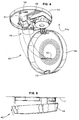
- Figure 4 illustrates a smoke detector 40 in accordance with the present invention.
- the detector 40 has a base 42 and a hingedly mounted cover 44.
- the base 42 carries a conventional ionization-type detection apparatus generally indicated at 46.
- first and second battery retaining prongs 48 and 50 are also on the base 42.
- the cover 44 carries a blocking flange 52.
- the cover 44 can be latched to the base 42 by a latch member 54 carried on the base 42 which releasably engages a latch notch 56 carried on the cover 44.
- the blocking flange 52 drops between the battery retaining prongs 48 and 50 allowing the latch 54 to engage the latch retaining recess 56 in the cover 44. In the absence of a battery the blocking flange 52 comes into contact with the free ends of the battery retaining members 48 and 50 and the cover 44 is blocked from closing thereby as illustrated generally in Figure 3A.
- Figure 5 illustrates the detector 40 mounted on a ceiling C as is conventional.
- the cover 44 will hang open in the absence of a battery providing a visual indication of that absence. With the battery present, the cover 44 can be latched closed against the base 42.
- FIGS. 6A, 6B and 6C illustrate an alternate embodiment 60.
- the embodiment 60 includes a base 62 which can be affixed to a ceiling or wall surface S.
- the unit 60 also includes a cover 64.
- the cover 64 can be latched to the base 62 in the presence of a battery B as illustrated in Figure 6A.
- the latch members 66a and 66b carried thereon cannot simultaneously engage the cover 64.
- the engagement is blocked by flange 68 which intersects first and second battery prongs 70a and 70b, of which only 70a is illustrated.
- the prongs 70a and 70b are the same general type prongs as illustrated previously in Figure 1 as prongs 24 and 26.
Landscapes
- Physics & Mathematics (AREA)
- General Physics & Mathematics (AREA)
- Business, Economics & Management (AREA)
- Emergency Management (AREA)
- Engineering & Computer Science (AREA)
- Analytical Chemistry (AREA)
- Chemical & Material Sciences (AREA)
- Computer Security & Cryptography (AREA)
- Fire-Detection Mechanisms (AREA)
- Battery Mounting, Suspending (AREA)
- Secondary Cells (AREA)
- Emergency Alarm Devices (AREA)
- Fire Alarms (AREA)
Claims (5)
- Vorrichtung zum Verhindern einer Verriegelung eines Deckels (14; 64) an einem Grundkörper (12; 42; 62) einer batteriebetriebenen Einheit beim Fehlen einer Batterie (B), umfassend
ein erstes, elastisches, sich längs erstreckendes Batterie-Halteteil (24; 48; 70a), wobei das Teil ein freies Ende (24b) hat, das in Abhängigkeit vom Vorhandensein der Batterie (B) auslenkbar ist; und
eine Verriegelungsvorrichtung (30, 32; 54, 56; 66a, 66b), die zumindest teilweise entweder auf dem Grundkörper oder dem Deckel angeordnet ist;
wobei die Vorrichtung gekennzeichnet ist durch
ein zweites, elastisches, sich längs erstreckendes Batterie-Halteteil (26; 50; 70b), wobei die ersten und zweiten Batterie-Halteteile (24, 26; 48, 50; 70a, 70b) im Abstand voneinander angeordnet und gegeneinander vorgespannt sowie von einem der beiden Teile, nämlich dem Grundkörper oder dem Deckel, getragen werden, wobei die Teile jeweils ein freies, die Batterie haltendes Ende (24b, 26b) haben und die Enden in Abhängigkeit von dem Vorhandensein der Batterie (B) voneinander weg ausblenkbar sind; und
durch einen Blockierflansch (28; 52; 68), der von dem anderen der beiden Teile, nämlich dem Grundkörper oder dem Deckel, getragen wird, wobei der Flansch zumindest an einem der Enden (24b, 26b) beim Fehlen der Batterie anliegt, wodurch die Verriegelung des Deckels an dem Grundkörper verhindert wird. - Vorrichtung nach Anspruch 1, wobei die Batterie-Halteteile (24, 26; 48, 50; 70a, 70b) und der Blockierflansch (28; 52; 68) so ausgerichtet sind, daß beim Vorhandensein der Batterie (B) der Flansch zwischen die genannten Teile bewegt wird.
- Vorrichtung nach Anspruch 1 oder 2, wobei der Blockierflansch (28; 52; 68) an beiden Enden (24b, 26b) anliegt.
- Vorrichtung nach Anspruch 1, wobei der Blockierflansch (28; 52; 68) eine im allgemeinen rechtwinklige Form hat und der Deckel (14; 44; 64) gegen den Grundkörper (12; 42; 62) nur beim Vorhandensein der Batterie (B) schließbar ist.
- Vorrichtung nach Anspruch 4, wobei ein Scharnier (16) zwischen dem Deckel (14) und dem Grundkörper (12) vorgesehen ist.
Applications Claiming Priority (2)
| Application Number | Priority Date | Filing Date | Title |
|---|---|---|---|
| US07/485,221 US5191855A (en) | 1990-02-26 | 1990-02-26 | Battery missing indicator |
| US485221 | 1995-06-07 |
Publications (2)
| Publication Number | Publication Date |
|---|---|
| EP0445346A1 EP0445346A1 (de) | 1991-09-11 |
| EP0445346B1 true EP0445346B1 (de) | 1995-04-05 |
Family
ID=23927367
Family Applications (1)
| Application Number | Title | Priority Date | Filing Date |
|---|---|---|---|
| EP90111466A Expired - Lifetime EP0445346B1 (de) | 1990-02-26 | 1990-06-18 | Indikator für das Fehlen einer Batterie |
Country Status (5)
| Country | Link |
|---|---|
| US (1) | US5191855A (de) |
| EP (1) | EP0445346B1 (de) |
| JP (1) | JPH03254062A (de) |
| CA (1) | CA2020025C (de) |
| DE (1) | DE69018441T2 (de) |
Families Citing this family (51)
| Publication number | Priority date | Publication date | Assignee | Title |
|---|---|---|---|---|
| JP2606954B2 (ja) * | 1990-08-30 | 1997-05-07 | シャープ株式会社 | 電池の収納構造 |
| US5646598A (en) * | 1995-05-02 | 1997-07-08 | Nickles; Aaron Michael | Smoke detector with advanced safety features |
| US6160487A (en) * | 1999-07-22 | 2000-12-12 | Kidde Walter Portable Equipment Inc | Single lockout mechanism for a multiple battery compartment that is particularly suited for smoke and carbon monoxide detector apparatus |
| US6446926B1 (en) * | 2001-01-26 | 2002-09-10 | Thomas J. Kaschuk | Smoke alarm retaining apparatus |
| US8034026B2 (en) * | 2001-05-18 | 2011-10-11 | Deka Products Limited Partnership | Infusion pump assembly |
| EP1815879A3 (de) * | 2001-05-18 | 2007-11-14 | Deka Products Limited Partnership | Infusionsset für eine Flüssigkeitspumpe |
| US7492273B2 (en) * | 2003-03-10 | 2009-02-17 | Walter Kidde Portable Equipment, Inc. | Pivoting battery carrier and a life safety device incorporating the same |
| GB2420899A (en) * | 2004-12-06 | 2006-06-07 | Peter Frost-Gaskin | Smoke alarm housing |
| US11027058B2 (en) | 2006-02-09 | 2021-06-08 | Deka Products Limited Partnership | Infusion pump assembly |
| US11478623B2 (en) | 2006-02-09 | 2022-10-25 | Deka Products Limited Partnership | Infusion pump assembly |
| CN104162200B (zh) | 2006-02-09 | 2018-03-27 | 德卡产品有限公司 | 外围系统 |
| US11497846B2 (en) | 2006-02-09 | 2022-11-15 | Deka Products Limited Partnership | Patch-sized fluid delivery systems and methods |
| US12151080B2 (en) | 2006-02-09 | 2024-11-26 | Deka Products Limited Partnership | Adhesive and peripheral systems and methods for medical devices |
| US12070574B2 (en) | 2006-02-09 | 2024-08-27 | Deka Products Limited Partnership | Apparatus, systems and methods for an infusion pump assembly |
| US11364335B2 (en) | 2006-02-09 | 2022-06-21 | Deka Products Limited Partnership | Apparatus, system and method for fluid delivery |
| US12274857B2 (en) | 2006-02-09 | 2025-04-15 | Deka Products Limited Partnership | Method and system for shape-memory alloy wire control |
| US9492606B2 (en) | 2006-02-09 | 2016-11-15 | Deka Products Limited Partnership | Apparatus, system and methods for an infusion pump assembly |
| US11318249B2 (en) | 2006-02-09 | 2022-05-03 | Deka Products Limited Partnership | Infusion pump assembly |
| EP2121077A1 (de) | 2007-02-09 | 2009-11-25 | Deka Products Limited Partnership | Automatisierte insertionsanordnung |
| US7799991B1 (en) | 2007-10-31 | 2010-09-21 | Yazaki North America, Inc. | Bus bar position assurance device |
| US9111425B2 (en) * | 2007-12-20 | 2015-08-18 | Cooper Technologies Company | Indicating devices and associated methods |
| US9494476B2 (en) | 2007-12-20 | 2016-11-15 | Cooper Technologies Company | Indicator device for an enclosure with sealing compound |
| CN110251769B (zh) * | 2007-12-31 | 2022-04-01 | 德卡产品有限公司 | 输注泵组件 |
| US10188787B2 (en) | 2007-12-31 | 2019-01-29 | Deka Products Limited Partnership | Apparatus, system and method for fluid delivery |
| WO2009088956A2 (en) * | 2007-12-31 | 2009-07-16 | Deka Products Limited Partnership | Infusion pump assembly |
| US10080704B2 (en) | 2007-12-31 | 2018-09-25 | Deka Products Limited Partnership | Apparatus, system and method for fluid delivery |
| US8881774B2 (en) | 2007-12-31 | 2014-11-11 | Deka Research & Development Corp. | Apparatus, system and method for fluid delivery |
| US8900188B2 (en) | 2007-12-31 | 2014-12-02 | Deka Products Limited Partnership | Split ring resonator antenna adapted for use in wirelessly controlled medical device |
| US12447265B2 (en) | 2007-12-31 | 2025-10-21 | Deka Products Limited Partnership | Apparatus, system and method for fluid delivery |
| US9456955B2 (en) | 2007-12-31 | 2016-10-04 | Deka Products Limited Partnership | Apparatus, system and method for fluid delivery |
| WO2010031059A2 (en) | 2008-09-15 | 2010-03-18 | Deka Products Limited Partnership | Systems and methods for fluid delivery |
| US9180245B2 (en) | 2008-10-10 | 2015-11-10 | Deka Products Limited Partnership | System and method for administering an infusible fluid |
| US8066672B2 (en) | 2008-10-10 | 2011-11-29 | Deka Products Limited Partnership | Infusion pump assembly with a backup power supply |
| US8223028B2 (en) | 2008-10-10 | 2012-07-17 | Deka Products Limited Partnership | Occlusion detection system and method |
| US8262616B2 (en) * | 2008-10-10 | 2012-09-11 | Deka Products Limited Partnership | Infusion pump assembly |
| US12370327B2 (en) | 2008-10-10 | 2025-07-29 | Deka Products Limited Partnership | Infusion pump methods, systems and apparatus |
| US8708376B2 (en) * | 2008-10-10 | 2014-04-29 | Deka Products Limited Partnership | Medium connector |
| US8016789B2 (en) * | 2008-10-10 | 2011-09-13 | Deka Products Limited Partnership | Pump assembly with a removable cover assembly |
| US12186531B2 (en) | 2008-10-10 | 2025-01-07 | Deka Products Limited Partnership | Infusion pump assembly |
| US8267892B2 (en) | 2008-10-10 | 2012-09-18 | Deka Products Limited Partnership | Multi-language / multi-processor infusion pump assembly |
| JP4676524B2 (ja) * | 2008-10-22 | 2011-04-27 | 能美防災株式会社 | 火災警報器 |
| US8179276B2 (en) * | 2009-09-29 | 2012-05-15 | Tyco Healthcare Group Lp | Battery assembly with alarm |
| CA2787178C (en) | 2010-01-22 | 2019-02-12 | Deka Products Limited Partnership | Method and system for shape-memory alloy wire control |
| US11524151B2 (en) | 2012-03-07 | 2022-12-13 | Deka Products Limited Partnership | Apparatus, system and method for fluid delivery |
| JP5923758B2 (ja) * | 2012-06-28 | 2016-05-25 | パナソニックIpマネジメント株式会社 | 電池駆動式感知器 |
| FR3004061B1 (fr) * | 2013-03-26 | 2015-03-27 | Hager Security | Coffret comprenant deux parties articulees munies de moyen de verrouillage |
| WO2015003145A1 (en) | 2013-07-03 | 2015-01-08 | Deka Products Limited Partnership | Apparatus, system and method for fluid delivery |
| EP3537499A4 (de) * | 2016-11-02 | 2019-12-04 | SZ DJI Technology Co., Ltd. | Batterieaufnahmevorrichtung und unbemanntes luftfahrzeug |
| US11523972B2 (en) | 2018-04-24 | 2022-12-13 | Deka Products Limited Partnership | Apparatus, system and method for fluid delivery |
| CN110065561A (zh) * | 2019-04-25 | 2019-07-30 | 潍坊红石星机械加工有限公司 | 电动三轮车的电池防盗装置 |
| US11676476B2 (en) * | 2021-05-14 | 2023-06-13 | SimpliSafe, Inc. | Battery tamper indicator for detector |
Family Cites Families (9)
| Publication number | Priority date | Publication date | Assignee | Title |
|---|---|---|---|---|
| US3529567A (en) * | 1968-09-06 | 1970-09-22 | Detection Ltd | Mechanical fire detection alarm device |
| JPS5734445Y2 (de) * | 1977-08-19 | 1982-07-29 | ||
| US4227191A (en) * | 1978-02-21 | 1980-10-07 | Samuel Raber | Light emitting smoke detector |
| US4228428A (en) * | 1979-04-02 | 1980-10-14 | Niedermeyer Karl O | Visible signal for alarm, such as a smoke detector |
| US4525703A (en) * | 1982-08-23 | 1985-06-25 | General Electric Company | Portable smoke alarm |
| US4533904A (en) * | 1984-02-27 | 1985-08-06 | Steinman Jr Leroy F | Combination smoke and burglar alarm |
| US4870395A (en) * | 1988-03-10 | 1989-09-26 | Seatt Corporation | Battery powered smoke alarm safety lockout system |
| US4881063A (en) * | 1989-01-30 | 1989-11-14 | Ei Company, Ltd. | Battery removal indicator |
| US5055830A (en) * | 1989-06-12 | 1991-10-08 | Pittway Corporation | Battery sensing mechanism |
-
1990
- 1990-02-26 US US07/485,221 patent/US5191855A/en not_active Expired - Lifetime
- 1990-06-18 DE DE69018441T patent/DE69018441T2/de not_active Expired - Lifetime
- 1990-06-18 EP EP90111466A patent/EP0445346B1/de not_active Expired - Lifetime
- 1990-06-27 CA CA002020025A patent/CA2020025C/en not_active Expired - Lifetime
- 1990-07-11 JP JP2183873A patent/JPH03254062A/ja active Pending
Also Published As
| Publication number | Publication date |
|---|---|
| DE69018441T2 (de) | 1996-01-04 |
| US5191855A (en) | 1993-03-09 |
| EP0445346A1 (de) | 1991-09-11 |
| DE69018441D1 (de) | 1995-05-11 |
| JPH03254062A (ja) | 1991-11-13 |
| CA2020025A1 (en) | 1991-08-27 |
| CA2020025C (en) | 1994-11-08 |
Similar Documents
| Publication | Publication Date | Title |
|---|---|---|
| EP0445346B1 (de) | Indikator für das Fehlen einer Batterie | |
| US5055830A (en) | Battery sensing mechanism | |
| US5103216A (en) | Improperly inserted battery detector | |
| US4881063A (en) | Battery removal indicator | |
| US4438428A (en) | Multiple function personal security alarm | |
| US5489890A (en) | Portable alarm device for entryway motion monitoring | |
| US4525703A (en) | Portable smoke alarm | |
| AU2008237716B2 (en) | Fire alarm and like devices | |
| WO2004044859A1 (en) | Warning unit | |
| US4567477A (en) | Smoke detector switch indicator | |
| WO1992007155A1 (en) | Lock monitor | |
| US4170334A (en) | Theft-deterrent bracket for smoke alarms | |
| US7414539B2 (en) | Simple alarm device | |
| EP0800694B1 (de) | Branddetektor- identifizierung | |
| JP4284533B2 (ja) | 壁掛け型火災警報器 | |
| CN217101450U (zh) | 集尘袋状态的检测结构以及集尘桶 | |
| JP3843936B2 (ja) | 住宅用防災感知器 | |
| CA1188773A (en) | Smoke detector indicator | |
| EP0568137A1 (de) | Montagestruktur für elektrisches Gerät mit Anzeigevorrichtung seiner Entfernung | |
| JP2004145758A (ja) | 検知器 | |
| KR800001444Y1 (ko) | 경보장치가 부설된 자물쇠 | |
| JPH10214384A (ja) | 携帯用ドアガード | |
| JPH09173488A (ja) | 消火器の持出し防止装置 | |
| JPH1011685A (ja) | 遠隔試験機能付火災監視システムの試験用ターミナル | |
| JPH0676677A (ja) | スイッチの取付け構造 |
Legal Events
| Date | Code | Title | Description |
|---|---|---|---|
| PUAI | Public reference made under article 153(3) epc to a published international application that has entered the european phase |
Free format text: ORIGINAL CODE: 0009012 |
|
| AK | Designated contracting states |
Kind code of ref document: A1 Designated state(s): DE FR GB |
|
| 17P | Request for examination filed |
Effective date: 19920117 |
|
| 17Q | First examination report despatched |
Effective date: 19930719 |
|
| GRAA | (expected) grant |
Free format text: ORIGINAL CODE: 0009210 |
|
| AK | Designated contracting states |
Kind code of ref document: B1 Designated state(s): DE FR GB |
|
| REF | Corresponds to: |
Ref document number: 69018441 Country of ref document: DE Date of ref document: 19950511 |
|
| ET | Fr: translation filed | ||
| PLBE | No opposition filed within time limit |
Free format text: ORIGINAL CODE: 0009261 |
|
| STAA | Information on the status of an ep patent application or granted ep patent |
Free format text: STATUS: NO OPPOSITION FILED WITHIN TIME LIMIT |
|
| 26N | No opposition filed | ||
| REG | Reference to a national code |
Ref country code: GB Ref legal event code: 732E |
|
| REG | Reference to a national code |
Ref country code: FR Ref legal event code: TP |
|
| REG | Reference to a national code |
Ref country code: GB Ref legal event code: IF02 |
|
| PGFP | Annual fee paid to national office [announced via postgrant information from national office to epo] |
Ref country code: FR Payment date: 20090605 Year of fee payment: 20 |
|
| PGFP | Annual fee paid to national office [announced via postgrant information from national office to epo] |
Ref country code: GB Payment date: 20090522 Year of fee payment: 20 Ref country code: DE Payment date: 20090630 Year of fee payment: 20 |
|
| REG | Reference to a national code |
Ref country code: GB Ref legal event code: PE20 Expiry date: 20100617 |
|
| PG25 | Lapsed in a contracting state [announced via postgrant information from national office to epo] |
Ref country code: GB Free format text: LAPSE BECAUSE OF EXPIRATION OF PROTECTION Effective date: 20100617 |
|
| PG25 | Lapsed in a contracting state [announced via postgrant information from national office to epo] |
Ref country code: DE Free format text: LAPSE BECAUSE OF EXPIRATION OF PROTECTION Effective date: 20100618 |