EP0445363A1 - Dispositif de fraisage ou perçage - Google Patents
Dispositif de fraisage ou perçage Download PDFInfo
- Publication number
- EP0445363A1 EP0445363A1 EP90121426A EP90121426A EP0445363A1 EP 0445363 A1 EP0445363 A1 EP 0445363A1 EP 90121426 A EP90121426 A EP 90121426A EP 90121426 A EP90121426 A EP 90121426A EP 0445363 A1 EP0445363 A1 EP 0445363A1
- Authority
- EP
- European Patent Office
- Prior art keywords
- template
- workpiece
- milling
- bores
- drilling
- Prior art date
- Legal status (The legal status is an assumption and is not a legal conclusion. Google has not performed a legal analysis and makes no representation as to the accuracy of the status listed.)
- Withdrawn
Links
- 238000005553 drilling Methods 0.000 title claims abstract description 49
- 238000003801 milling Methods 0.000 claims abstract description 58
- 238000004519 manufacturing process Methods 0.000 claims abstract description 10
- 230000000284 resting effect Effects 0.000 claims description 2
- 230000000149 penetrating effect Effects 0.000 claims 1
- 239000000463 material Substances 0.000 description 2
- 238000010276 construction Methods 0.000 description 1
- 239000002184 metal Substances 0.000 description 1
- 238000000034 method Methods 0.000 description 1
- 239000004033 plastic Substances 0.000 description 1
- 239000002023 wood Substances 0.000 description 1
Images



Classifications
-
- B—PERFORMING OPERATIONS; TRANSPORTING
- B23—MACHINE TOOLS; METAL-WORKING NOT OTHERWISE PROVIDED FOR
- B23B—TURNING; BORING
- B23B47/00—Constructional features of components specially designed for boring or drilling machines; Accessories therefor
- B23B47/28—Drill jigs for workpieces
-
- B—PERFORMING OPERATIONS; TRANSPORTING
- B23—MACHINE TOOLS; METAL-WORKING NOT OTHERWISE PROVIDED FOR
- B23B—TURNING; BORING
- B23B2247/00—Details of drilling jigs
- B23B2247/12—Drilling jigs with means to affix the jig to the workpiece
Definitions
- the invention relates to a milling or drilling device for producing depressions, holes, bores or the like to be produced in series at equal intervals in a workpiece. using a milling or drilling template that can be placed on the workpiece.
- Drilling templates for row holes are known from DE-OS 30 39 609. They consist of a base plate with a guide rail, into which holes are drilled, which are used to hold pins that have the function of side stops. There are matching holes on the top of these templates at equal intervals.
- the drill carriage, on which the drill is fastened in the form of a router, is guided over the base plate provided with a guide rail and is guided along the guide rail as a unit together with the drill carriage.
- a locking pin snaps into each fitting hole, whereupon the drill is inserted through the drilling slide and the drilling template into the workpiece to be machined.
- this known drilling template or combination of template and drilling device does not offer the possibility of rapidly producing depressions to be arranged one behind the other, in particular bores in workpiece surfaces, for example of Holes in the cabinet side walls for receiving cabinet base mounting plugs, since the drilling slide of the device must be repositioned after each hole in a cumbersome manner so that the drill reaches the following template hole, in particular no precautions are taken to ensure that the holes to be produced have a certain depth do not exceed.
- a device for adjusting the depth of cut of hand routers is also known (DGM 74 15 327), which is provided with a guide frame supported on the milling device and guided parallel to the axis of the milling tool and with at least one stop arranged on this guide frame to limit the relative movement between the guide frame and milling device and has an adjusting rod in the form of a set screw, with which the distance between the guide frame and the milling device can be adjusted continuously, bores being provided for pushing rods through for the purpose of mounting on additional devices.
- DGM 74 15 327 A device for adjusting the depth of cut of hand routers is also known (DGM 74 15 327), which is provided with a guide frame supported on the milling device and guided parallel to the axis of the milling tool and with at least one stop arranged on this guide frame to limit the relative movement between the guide frame and milling device and has an adjusting rod in the form of a set screw, with which the distance between the guide frame and the milling device can be adjusted continuously, bores being provided for pushing rod
- this device does not offer the possibility of simply producing rows of holes on workpiece surfaces, since it requires a template for this.
- the template of the type mentioned above were combined with the latter device, the disadvantages of the known drilling template described above in the production of such rows of holes could not be eliminated.
- the object of the invention is therefore to develop the milling or drilling device of the type mentioned in such a way that, in conjunction with a template, it enables simple production of depressions, holes or bores arranged in rows at equal intervals in workpiece surfaces, with the use of them
- Such a device is intended in particular in craft workshops, in which such devices are still guided by hand over the workpieces to be machined.
- a positioning rod which is adjustably fastened to the milling or drilling device in the milling feed direction and parallel to it, and which has the respective recess of the template lying on the surface of the workpiece to be machined, the at least one of which can be placed on the outer edge of the workpiece Has stop, reaches through to the workpiece surface.
- the basic idea of the invention is thus to attach a sensor to the milling or drilling device parallel to the tool feed direction, i.e. the lowering direction of the drill or milling cutter, which for positioning is immersed in a recess in the template which is at the same distance from the location of the desired material removal as the sensor from the axis of the milling or drilling tool. It is thereby achieved that the milling or drilling tool only has to be displaced in each case in the case of depressions to be produced in series until the sensor, which has the shape of a
- Positioning rod engages in the next recess of the template, which then automatically sets the correct distance for the hole to be produced, without the need for time-consuming and labor-intensive adjustment processes.
- the positioning rod can also be used as a depth limiter which engages in the aforementioned bore and through it into the respective positioning recess of the Template is insertable.
- the edge stop or edges of the template can be pivotably attached with respect to the edge edges of the workpiece to be machined.
- the device according to the invention has proven particularly useful in connection with templates for the production of straight rows of holes, the template consisting of a long lath-shaped body of approximately rectangular cross-section, which along its surface with the positioning bores arranged one behind the other for the positioning rod and at the same time depth limiters and along its center line is provided with bores to be penetrated by the milling tool and are located in a longitudinal groove of the template, which also serves as a running guide for the router.
- the template can be connected to a mounting and guide device, consisting of two mutually parallel angular profile rails, which can be held at an adjustable distance from one another by at least one connecting flap articulated with both profile rails , which corresponds in each case to the thickness of the workpiece on which the template is placed and which is provided with connecting pins which cut into the recesses, bores and the like. engage the template.
- the adjustability of the distance between the two angle rails relative to one another can also be infinitely variable with the aid of the connecting link or links, which are rotatably attached to one leg of each angle profile rail, which makes it possible to match this distance exactly to the thickness of the workpiece to be machined , on which the mounting and guiding device carrying the milling and drilling device can be fitted.
- the mounting of the milling or drilling device itself on the mounting and guiding device can be accomplished particularly cheaply in that the connecting pins are arranged on the connecting straps and extend in the direction of the bottom of the template.
- the template for the production of straight rows of holes consists of a long lath-shaped body of approximately rectangular cross-section, which is provided along its center line with holes to be penetrated by the milling or drilling tool, which are located in a longitudinal groove of the template, which also serves as a guide for the router, and that Milling or drilling tool is surrounded by a thrust ring body, the diameter or outline of which corresponds to the diameter or outline of the recesses, bores and the like to be penetrated by the milling or drilling tool. corresponds to and in these recesses, holes and the like. can be snapped into place.
- This solution represents a certain simplification compared to the first-mentioned solution insofar as the use of a positioning rod which is adjustably fastened to the milling or drilling device in the milling feed direction A and parallel to it, and which has the respective recesses in the surface of the workpiece to be machined reaches over the template, is dispensed with.
- the template can be connected to a holding and guiding device, consisting of two mutually parallel angle profile rails, which are connected by at least one with the two profiles hinged connection tab can be kept at an adjustable distance from each other, which corresponds to the thickness of the workpiece, on which the template is placed and which is provided with connecting pins, which in the recesses, bores and the like. engage the template.
- the milling or drilling device 1 shown in FIG. 1 is a router which can be moved by hand using a template 3 shown in FIGS. 2 to 5, on which it rests with a guide table 10.
- the underside of the template lies on the surface 4 of a workpiece 6 to be machined, which is made of any material, for example wood, plastic or metal, and in which, with the aid of a milling tool 11, a large number are arranged one after the other at equal intervals Holes of a certain depth are to be made, which are to be used to receive cabinet base mounting pins.
- a positioning rod 2 is adjustably attached, which generally designates the respective bore 5 as a recess which extends through the template 3 lying on the surface 4 of the workpiece 6 to be machined.
- This positioning rod is therefore part of the router, but at the same time also a functional part of the template, since it is moved by hand when the Router engages in the longitudinal direction of the template in the successive bores 5, which are separated from one another by the same distance.
- This positioning rod is at the same time designed as a depth limiter for the bores to be produced in the workpiece 6, which means that the milling tool 11 only penetrates into the workpiece to a certain drilling depth.
- the guide table 10 of the router is provided with a bore passing through it and aligned with the depth limiter, through which the depth limiter can be inserted into the respective bore 5 of the template 3.
- edge edge stops 8 which can be pivoted with respect to the edge edges 9 of the workpiece 6 to be machined, so that the template 3, which in the embodiment shown is a long, lath-shaped body with an approximately rectangular cross section, can be held on at least one workpiece edge so that it cannot move on the workpiece surface.
- the template can be clamped to the workpiece by means of clamps, as shown at 14 in FIG.
- the longitudinal groove 13 located in the center line of the template body, in the bottom of which there are the bores 12 to be penetrated by the milling tool 11, the spacings of which correlate with the spacing of the bores or recesses 5 in the template, serves as a guide for the milling tool 11 and has the advantage that that the router does not have to be lifted from milling to milling, but can be moved in this longitudinal groove from a bore 5 until the depth limiter or positioning rod 2 can be immersed in the next bore.
- the bores 5 which are not to be used can be used with the aid of not shown Plugs are closed so that when the router or its guide table 10 and thus milling tool 11 is pushed further in the longitudinal groove 13, these closed bores 5 are overrun by the positioning rod 2 and depth limiter. In this way it is possible to easily adapt a template to different drilling programs in the production of drilling rows in, for example, cabinet sides of furniture.
- the template 3 can, if necessary, be easily extended by further lengths, with the locking pins as connecting elements serve between the successive lengths.
- the connector or connectors 8, which are located on the outer edges 7 of the template 3, can be provided with spacing screws 16a, by means of which an exact adjustment of the template with respect to the workpiece 6 to be machined is possible.
- the spacing screws are screwed against the edge 9 of the workpiece.
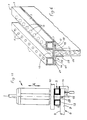
- the template 3 is connected to a holding and guiding device 25, consisting of two mutually parallel angular profile rails 16, 17, which can be held at an adjustable distance from one another by at least one connecting bracket 18 articulated to the two profiled rails are, as can be seen in detail from FIGS. 7 to 9, which show the holding and guiding device 25 separately from the template 3.
- a holding and guiding device 25 consisting of two mutually parallel angular profile rails 16, 17, which can be held at an adjustable distance from one another by at least one connecting bracket 18 articulated to the two profiled rails are, as can be seen in detail from FIGS. 7 to 9, which show the holding and guiding device 25 separately from the template 3.
- the two parallel profiled rails 16 and 17 are connected to one another in an articulated manner by three connecting straps 18 which are adjacent to one another at a distance, by virtue of the fact that these straps with one leg 24, 26 of the two rectangular profiled rails 16 and 17 lying in a common plane are in rotary connection by means of pins 19 and 20, these pins each being arranged at the same distance a from the longitudinal center line of the device 25.
- these pivot pins 19, 20, as can be seen from FIG. 10 the two parallel profile rails can be displaced with respect to one another, as a result of which their mutual distance B can be set. The size of this distance depends on the thickness of the workpiece 22 (FIG.
- FIGS. 1 and 11 on which the holding and guiding device and thus the template is to be placed, and which may be, for example, a cabinet door or wall or similar plate-like structure can, which is to be provided in its end face with the aid of a milling or drilling tool 11, which is shown schematically in FIGS. 1 and 11, with cutouts, bores or the like.
- a milling or drilling tool 11 which is shown schematically in FIGS. 1 and 11, with cutouts, bores or the like.
- a thrust ring body 29 which surrounds the milling or drilling tool 11 and whose diameter or Outline corresponds to the diameter or outline of the recesses, bores 12 or the like to be penetrated by the milling or drilling tool.
- this thrust ring body is at a distance from the guide table 10 which is greater than the distance of this table from the surface 4 of the workpiece 6 to be machined, so that the thrust ring body 29 into the bores 12 or the like in the bottom 13 of the template 3 can occur and thereby represents a guide for the milling or drilling tool 11 without the need for a positioning rod.
- a holding and guiding device 25 of the type described above consisting of two mutually parallel angle profile rails 16 and 17, which are connected by at least one connecting bracket 18 articulated to the two profile rails can be kept at an adjustable distance from one another, which corresponds in each case to the thickness of the workpiece on which the template is placed and which is provided with connecting pins 23 which engage in the bores 12 or the like of the template.
- a mounting and guiding device shown in FIGS. 7 to 10.
- the template 3 so that instead of the cross-sectional profile shown in FIGS. 2 and 5, which is characterized by a guide groove for the router, it does not have such a groove, but instead forms a flat body with a rectangular cross-sectional profile and to provide them with bores or recesses, the outline and profile of which correspond to the recesses to be produced in the workpiece, and in addition the templates of the type described above or mentioned at the beginning with all Markings can be provided, which are required for attaching fittings or for creating workpieces, for example furniture parts.
- the holding and guiding device or with its angular profile rails 16, 17 need only from the template to be removed by pulling the connecting pins out of the holes 12 of the template.
Landscapes
- Engineering & Computer Science (AREA)
- Mechanical Engineering (AREA)
- Milling, Drilling, And Turning Of Wood (AREA)
Applications Claiming Priority (2)
| Application Number | Priority Date | Filing Date | Title |
|---|---|---|---|
| DE19904000456 DE4000456A1 (de) | 1990-01-09 | 1990-01-09 | Fraes- oder bohrvorrichtung |
| DE4000456 | 1990-01-09 |
Publications (1)
| Publication Number | Publication Date |
|---|---|
| EP0445363A1 true EP0445363A1 (fr) | 1991-09-11 |
Family
ID=6397789
Family Applications (1)
| Application Number | Title | Priority Date | Filing Date |
|---|---|---|---|
| EP90121426A Withdrawn EP0445363A1 (fr) | 1990-01-09 | 1990-11-08 | Dispositif de fraisage ou perçage |
Country Status (2)
| Country | Link |
|---|---|
| EP (1) | EP0445363A1 (fr) |
| DE (1) | DE4000456A1 (fr) |
Cited By (5)
| Publication number | Priority date | Publication date | Assignee | Title |
|---|---|---|---|---|
| EP0666130A1 (fr) * | 1994-02-04 | 1995-08-09 | Black & Decker Inc. | Dispositif de perçage avec bras de rallonge |
| EP0824998A1 (fr) * | 1996-08-23 | 1998-02-25 | Peter Martin Dufter | Outil pour la manutention d'une machine-outil |
| EP1279467A1 (fr) * | 2001-07-26 | 2003-01-29 | Festool GmbH | Système pour guider un outil portatif, en particulier une fraiseuse |
| GB2425082A (en) * | 2005-04-13 | 2006-10-18 | Jointgenie Ltd | Drilling jigs |
| CN111923140A (zh) * | 2020-08-03 | 2020-11-13 | 黄美凤 | 一种可调节间距的表带钻孔装置 |
Families Citing this family (1)
| Publication number | Priority date | Publication date | Assignee | Title |
|---|---|---|---|---|
| DE102023003509A1 (de) * | 2023-08-25 | 2025-02-27 | Thomas Harder | Führungsanschlag mit halbautomatischer Zentrierfunktion für Oberfräsen |
Citations (3)
| Publication number | Priority date | Publication date | Assignee | Title |
|---|---|---|---|---|
| FR2318011A1 (fr) * | 1975-07-18 | 1977-02-11 | Pinot Jean | Dispositif de percage et de fraisage de bois et autres materiaux |
| CH619636A5 (en) * | 1977-04-22 | 1980-10-15 | Fritz Haldemann | Arrangement for drilling rows of holes with a portable router |
| AT384976B (de) * | 1985-11-20 | 1988-02-10 | Pfohl Hans | Vorrichtung zur halterung eines bohrgeraetes |
-
1990
- 1990-01-09 DE DE19904000456 patent/DE4000456A1/de not_active Withdrawn
- 1990-11-08 EP EP90121426A patent/EP0445363A1/fr not_active Withdrawn
Patent Citations (3)
| Publication number | Priority date | Publication date | Assignee | Title |
|---|---|---|---|---|
| FR2318011A1 (fr) * | 1975-07-18 | 1977-02-11 | Pinot Jean | Dispositif de percage et de fraisage de bois et autres materiaux |
| CH619636A5 (en) * | 1977-04-22 | 1980-10-15 | Fritz Haldemann | Arrangement for drilling rows of holes with a portable router |
| AT384976B (de) * | 1985-11-20 | 1988-02-10 | Pfohl Hans | Vorrichtung zur halterung eines bohrgeraetes |
Cited By (7)
| Publication number | Priority date | Publication date | Assignee | Title |
|---|---|---|---|---|
| EP0666130A1 (fr) * | 1994-02-04 | 1995-08-09 | Black & Decker Inc. | Dispositif de perçage avec bras de rallonge |
| US5609444A (en) * | 1994-02-04 | 1997-03-11 | Black & Decker Inc. | Drilling device with an extension arm |
| EP0824998A1 (fr) * | 1996-08-23 | 1998-02-25 | Peter Martin Dufter | Outil pour la manutention d'une machine-outil |
| EP1279467A1 (fr) * | 2001-07-26 | 2003-01-29 | Festool GmbH | Système pour guider un outil portatif, en particulier une fraiseuse |
| GB2425082A (en) * | 2005-04-13 | 2006-10-18 | Jointgenie Ltd | Drilling jigs |
| GB2425082B (en) * | 2005-04-13 | 2009-07-15 | Jointgenie Ltd | Drilling jigs |
| CN111923140A (zh) * | 2020-08-03 | 2020-11-13 | 黄美凤 | 一种可调节间距的表带钻孔装置 |
Also Published As
| Publication number | Publication date |
|---|---|
| DE4000456A1 (de) | 1991-07-11 |
Similar Documents
| Publication | Publication Date | Title |
|---|---|---|
| DE1427765C3 (de) | Führungseinrichtung für eine Betonschneidmaschine | |
| DE2734343C2 (de) | Werkbank mit Spanneinrichtung | |
| EP1091067A1 (fr) | Charnière pour portes ou fenêtres | |
| DE3338943C2 (fr) | ||
| DE2611323C3 (de) | Einstellvorrichtung für eine der Höhe nach einstellbare obere Schiene eines Schiebeflügels | |
| DE3141158C2 (de) | Führungsvorrichtung für einen ein- und ausfahrbaren Einsatz im Korpus eines Schrankes | |
| DE1809616C3 (de) | Verstellbares Möbelscharnier Zusätzen: 21 Ol 082 | |
| EP0445363A1 (fr) | Dispositif de fraisage ou perçage | |
| DE9011467U1 (de) | Gerät zum Anbringen der Bohrungen zum Befestigen der Rahmenbandteile eines Fensters oder einer Türe | |
| DE3108437C2 (de) | Vorrichtung zum Montieren von Einbaudosen für Elektroinstallation | |
| EP0413203B1 (fr) | Dispositif de perçage | |
| DE8905851U1 (de) | Fräs- oder Bohrvorrichtung | |
| DE2810981C2 (de) | Vorrichtung zur Befestigung einer Zarge | |
| WO1997048087A1 (fr) | Support pour panneaux pivotants ou similaire | |
| EP3029234B1 (fr) | Ferrure d'angle réglable | |
| DE2225136A1 (de) | Verbesserungen an Werkstück-Spannvorrichtungen | |
| DE2461537A1 (de) | Vorrichtung zum fraesen und bohren von aussparungen in flaechen eines profilstabes | |
| DE2059558C3 (de) | Verstellbarer Endanschlag | |
| DE3008357A1 (de) | Handfraeswerkzeug | |
| DE1708341C3 (de) | Ausstellvorrichtung für einen Dreh-Kipp-Beschlag eines Fensters, einer Tür o.dgl | |
| DE19715423C2 (de) | Vorrichtung für das Fräsen von Zinken oder das Einbringen von Dübelbohrungen in zwei rechtwinkelig miteinander zu verbindende Bretter | |
| DE3915316A1 (de) | Fraes- oder bohrvorrichtung | |
| DE3219072A1 (de) | Verfahren zum herstellen von genau positionierten bohrungen in platten oder aehnlichen werkstuecken mit ebener oberflaeche und bohrmaschine zur durchfuehrung des neuen verfahrens | |
| DE2358028C3 (de) | Anreißlehre für Topfscharniere | |
| DE9407019U1 (de) | Bohrschablone |
Legal Events
| Date | Code | Title | Description |
|---|---|---|---|
| PUAI | Public reference made under article 153(3) epc to a published international application that has entered the european phase |
Free format text: ORIGINAL CODE: 0009012 |
|
| AK | Designated contracting states |
Kind code of ref document: A1 Designated state(s): AT BE CH DE DK ES FR GB GR IT LI LU NL SE |
|
| 17P | Request for examination filed |
Effective date: 19920302 |
|
| 17Q | First examination report despatched |
Effective date: 19931116 |
|
| STAA | Information on the status of an ep patent application or granted ep patent |
Free format text: STATUS: THE APPLICATION IS DEEMED TO BE WITHDRAWN |
|
| 18D | Application deemed to be withdrawn |
Effective date: 19950601 |