EP0445381A2 - Couverture thermo-rétractable - Google Patents
Couverture thermo-rétractable Download PDFInfo
- Publication number
- EP0445381A2 EP0445381A2 EP90122979A EP90122979A EP0445381A2 EP 0445381 A2 EP0445381 A2 EP 0445381A2 EP 90122979 A EP90122979 A EP 90122979A EP 90122979 A EP90122979 A EP 90122979A EP 0445381 A2 EP0445381 A2 EP 0445381A2
- Authority
- EP
- European Patent Office
- Prior art keywords
- heat
- reinforcing
- covering according
- shrinkable
- reinforcing component
- Prior art date
- Legal status (The legal status is an assumption and is not a legal conclusion. Google has not performed a legal analysis and makes no representation as to the accuracy of the status listed.)
- Granted
Links
Images
Classifications
-
- B—PERFORMING OPERATIONS; TRANSPORTING
- B32—LAYERED PRODUCTS
- B32B—LAYERED PRODUCTS, i.e. PRODUCTS BUILT-UP OF STRATA OF FLAT OR NON-FLAT, e.g. CELLULAR OR HONEYCOMB, FORM
- B32B27/00—Layered products comprising a layer of synthetic resin
- B32B27/12—Layered products comprising a layer of synthetic resin next to a fibrous or filamentary layer
-
- B—PERFORMING OPERATIONS; TRANSPORTING
- B29—WORKING OF PLASTICS; WORKING OF SUBSTANCES IN A PLASTIC STATE IN GENERAL
- B29C—SHAPING OR JOINING OF PLASTICS; SHAPING OF MATERIAL IN A PLASTIC STATE, NOT OTHERWISE PROVIDED FOR; AFTER-TREATMENT OF THE SHAPED PRODUCTS, e.g. REPAIRING
- B29C61/00—Shaping by liberation of internal stresses; Making preforms having internal stresses; Apparatus therefor
- B29C61/06—Making preforms having internal stresses, e.g. plastic memory
- B29C61/0608—Making preforms having internal stresses, e.g. plastic memory characterised by the configuration or structure of the preforms
- B29C61/0616—Making preforms having internal stresses, e.g. plastic memory characterised by the configuration or structure of the preforms layered or partially layered preforms, e.g. preforms with layers of adhesive or sealing compositions
-
- B—PERFORMING OPERATIONS; TRANSPORTING
- B29—WORKING OF PLASTICS; WORKING OF SUBSTANCES IN A PLASTIC STATE IN GENERAL
- B29C—SHAPING OR JOINING OF PLASTICS; SHAPING OF MATERIAL IN A PLASTIC STATE, NOT OTHERWISE PROVIDED FOR; AFTER-TREATMENT OF THE SHAPED PRODUCTS, e.g. REPAIRING
- B29C61/00—Shaping by liberation of internal stresses; Making preforms having internal stresses; Apparatus therefor
- B29C61/06—Making preforms having internal stresses, e.g. plastic memory
- B29C61/0608—Making preforms having internal stresses, e.g. plastic memory characterised by the configuration or structure of the preforms
- B29C61/0633—Preforms comprising reinforcing elements
-
- B—PERFORMING OPERATIONS; TRANSPORTING
- B29—WORKING OF PLASTICS; WORKING OF SUBSTANCES IN A PLASTIC STATE IN GENERAL
- B29C—SHAPING OR JOINING OF PLASTICS; SHAPING OF MATERIAL IN A PLASTIC STATE, NOT OTHERWISE PROVIDED FOR; AFTER-TREATMENT OF THE SHAPED PRODUCTS, e.g. REPAIRING
- B29C70/00—Shaping composites, i.e. plastics material comprising reinforcements, fillers or preformed parts, e.g. inserts
- B29C70/04—Shaping composites, i.e. plastics material comprising reinforcements, fillers or preformed parts, e.g. inserts comprising reinforcements only, e.g. self-reinforcing plastics
- B29C70/28—Shaping operations therefor
- B29C70/40—Shaping or impregnating by compression not applied
- B29C70/50—Shaping or impregnating by compression not applied for producing articles of indefinite length, e.g. prepregs, sheet moulding compounds [SMC] or cross moulding compounds [XMC]
-
- B—PERFORMING OPERATIONS; TRANSPORTING
- B32—LAYERED PRODUCTS
- B32B—LAYERED PRODUCTS, i.e. PRODUCTS BUILT-UP OF STRATA OF FLAT OR NON-FLAT, e.g. CELLULAR OR HONEYCOMB, FORM
- B32B27/00—Layered products comprising a layer of synthetic resin
- B32B27/32—Layered products comprising a layer of synthetic resin comprising polyolefins
-
- B—PERFORMING OPERATIONS; TRANSPORTING
- B32—LAYERED PRODUCTS
- B32B—LAYERED PRODUCTS, i.e. PRODUCTS BUILT-UP OF STRATA OF FLAT OR NON-FLAT, e.g. CELLULAR OR HONEYCOMB, FORM
- B32B5/00—Layered products characterised by the non- homogeneity or physical structure, i.e. comprising a fibrous, filamentary, particulate or foam layer; Layered products characterised by having a layer differing constitutionally or physically in different parts
- B32B5/02—Layered products characterised by the non- homogeneity or physical structure, i.e. comprising a fibrous, filamentary, particulate or foam layer; Layered products characterised by having a layer differing constitutionally or physically in different parts characterised by structural features of a fibrous or filamentary layer
- B32B5/022—Non-woven fabric
-
- B—PERFORMING OPERATIONS; TRANSPORTING
- B32—LAYERED PRODUCTS
- B32B—LAYERED PRODUCTS, i.e. PRODUCTS BUILT-UP OF STRATA OF FLAT OR NON-FLAT, e.g. CELLULAR OR HONEYCOMB, FORM
- B32B7/00—Layered products characterised by the relation between layers; Layered products characterised by the relative orientation of features between layers, or by the relative values of a measurable parameter between layers, i.e. products comprising layers having different physical, chemical or physicochemical properties; Layered products characterised by the interconnection of layers
- B32B7/04—Interconnection of layers
- B32B7/12—Interconnection of layers using interposed adhesives or interposed materials with bonding properties
-
- H—ELECTRICITY
- H02—GENERATION; CONVERSION OR DISTRIBUTION OF ELECTRIC POWER
- H02G—INSTALLATION OF ELECTRIC CABLES OR LINES, OR OF COMBINED OPTICAL AND ELECTRIC CABLES OR LINES
- H02G15/00—Cable fittings
- H02G15/08—Cable junctions
- H02G15/18—Cable junctions protected by sleeves, e.g. for communication cable
- H02G15/1806—Heat shrinkable sleeves
-
- B—PERFORMING OPERATIONS; TRANSPORTING
- B29—WORKING OF PLASTICS; WORKING OF SUBSTANCES IN A PLASTIC STATE IN GENERAL
- B29K—INDEXING SCHEME ASSOCIATED WITH SUBCLASSES B29B, B29C OR B29D, RELATING TO MOULDING MATERIALS OR TO MATERIALS FOR MOULDS, REINFORCEMENTS, FILLERS OR PREFORMED PARTS, e.g. INSERTS
- B29K2105/00—Condition, form or state of moulded material or of the material to be shaped
- B29K2105/06—Condition, form or state of moulded material or of the material to be shaped containing reinforcements, fillers or inserts
- B29K2105/12—Condition, form or state of moulded material or of the material to be shaped containing reinforcements, fillers or inserts of short lengths, e.g. chopped filaments, staple fibres or bristles
-
- B—PERFORMING OPERATIONS; TRANSPORTING
- B32—LAYERED PRODUCTS
- B32B—LAYERED PRODUCTS, i.e. PRODUCTS BUILT-UP OF STRATA OF FLAT OR NON-FLAT, e.g. CELLULAR OR HONEYCOMB, FORM
- B32B2305/00—Condition, form or state of the layers or laminate
- B32B2305/08—Reinforcements
-
- B—PERFORMING OPERATIONS; TRANSPORTING
- B32—LAYERED PRODUCTS
- B32B—LAYERED PRODUCTS, i.e. PRODUCTS BUILT-UP OF STRATA OF FLAT OR NON-FLAT, e.g. CELLULAR OR HONEYCOMB, FORM
- B32B2307/00—Properties of the layers or laminate
- B32B2307/70—Other properties
- B32B2307/732—Dimensional properties
- B32B2307/734—Dimensional stability
- B32B2307/736—Shrinkable
Definitions
- the invention relates to a heat-shrinkable covering, which consists of at least one shrinkable component in the form of a flat film, a reinforcing component attached thereon and a cover film connected to the shrinkable component.
- a heat-shrinkable object of this type is known from EP-A2 0 299 439.
- the reinforcement component essentially consists of ordered, lattice-shaped individual elements.
- the reinforcement elements are applied in such a way that the respective surface films are already in the crosslinked and stretched state, so that the reinforcement components are not subjected to stretching.
- the reinforcing elements are designed so that a change in shape corresponding to the shrinkage of the shrinkable component is possible.
- the reinforcing elements consist of short fibers (whiskers) made of inorganic materials, which are distributed in an irregular arrangement in the plastic.
- the manufacturing process for such an article is such that a mixture of a thermoplastic and the fibers is made, after which this mixture is extruded into a tape or tube.
- This strip or tube is then crosslinked, heated to a temperature above the crystal melting point of the plastic, deformed in the heat and then cooled in the stretched or expanded state.
- the short fibers are therefore part of the extrusion mass from the beginning and thus the later shrinking Component.
- the main disadvantage of such an arrangement is that it is difficult to insert threads of greater length, and that from the start the extrusion tool must be designed so that these additional components can be coextruded. There is also a risk that the fibers will align in the direction of extrusion during extrusion. In addition, there is the possibility that the fibers "drill out” from the surface and penetrate to the outside, particularly when shrinking. As a result of the extrusion process, the reinforcing fibers are hardly or only very difficult to control. In addition, the application of a very large proportion of fiber material makes it very difficult to apply very thin outer layers, it also having to be taken into account that the extruder screw must also transport this fiber material. For this reason, the lengths of the fibers are also chosen to be very short and should only be between 0.5 and 5 mm, which may not be enough for a particularly good and tear-resistant reinforcement arrangement.
- a heat-shrinkable object in which transverse to the stretching and shrinking direction, mutually parallel threads are provided, which run the full length of the heat-shrinkable object (that is, from one end to the other).
- Shorter fibers are scattered over this base of parallel individual threads, which are removed from a storage container and applied in an arbitrary distribution to the surface of the carrier tape provided with the threads.
- the fibers consist of cross-linked polymers, which means that pre-cross-linked fiber materials are already applied to the carrier layer. Difficulties are to be feared here in that the short pieces of fiber are applied to an already existing layer of continuous parallel threads and the reinforcing insert thus receives an overall somewhat inhomogeneous structure.
- the manufacturing process with respect to the reinforcement insert takes place in two steps: first, the parallel threads are applied to a carrier tape, for example made of hot-melt adhesive, and then the short fiber elements are fed in via a separate scattering and pouring device.
- a carrier tape for example made of hot-melt adhesive
- the present invention has for its object to develop a heat-shrinkable casing of the type mentioned so that its manufacture can be carried out in a simple manner and that it has good shrinking and reinforcing properties.
- this object is achieved in that a fiber material is applied in a disordered configuration on the surface film as a reinforcing component and that a firm connection is made between the reinforcing component, the surface film and the cover film.
- the invention has for its object to find a method with which an envelope of the type described can be produced in a simple manner.
- This object is achieved in that the reinforcing component is applied to an unstretched sheet, that the sheet and the reinforcing component are covered with a cover sheet and connected to form a uniform sheet-like structure, and that this sheet-like structure is heated, stretched and cooled in the stretched state.
- the heat-shrinkable covering according to the invention now has advantages over the prior art, the strength achieved against external stresses being achieved with a relatively easy-to-produce reinforcement component in combination with a shrinkable matrix. This is reflected in the structure of the heat-shrinkable covering itself, as well as in the simple and continuous process for producing the same.
- the basic idea of the invention for forming such a heat-shrinkable covering lies essentially in the fact that the reinforcing effect is due to transitions between materials of different mechanical strengths in the possible direction of cracking of the object.
- the previous models each have an ordered structure in which it is difficult to achieve the mobility of relatively long reinforcement elements required for shrinking.
- the regularity in the arrangement of the relatively long reinforcement elements is avoided and an isotropy is sought for the arrangement of the individual reinforcement elements in the form of fibers or threads.
- the individual reinforcing elements according to the invention can advantageously be molded together as a fleece or as a felt, or can also be sprinkled or placed loosely on the surface film in a disorderly manner in a special loading process.
- the application or spreading in its disorder per se can also be done in a deliberately even all-round distribution.
- the wrapping according to the invention has the advantage that this design of the reinforcing component in the form of a fleece, felt or the "disordered bed" with regard to the choice of material and the fineness of the structure, as well as the uniformity of all properties, allows a freely selectable combination. It must be ensured that the reinforcing component may cause the stretching process and the shrinking process or at least allow it without loosening the bond strength. This is not possible, for example, with flat inserts or with woven or knitted fabrics. In addition, the necessary resistance to crack formation is usually only provided in one direction.
- At least one of the covering films, the surface film and / or the covering film has shrinking properties. This causes the shrinking process, the reinforcing component at least passively participating in the shape changes, if not supported, if the individual reinforcing elements also have shrinking properties.
- the invention is also characterized in that the manufacturing process is very simple because it can be carried out in a continuous manner. It is particularly favorable to design the reinforcing component as a fleece or felt, so that it can then also be introduced into the manufacturing process as an independent molded part. The details of the possible method steps will be explained later with reference to the figures.
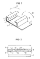
- FIG. 1 illustrates a sleeve in the form of a sleeve 1, as is usually used for covering objects, for example cables, splicing or the like.
- the size of the cuff 1 outlined depends in each case on the diameters of the object to be wrapped, which is why the actual wrapping part is outlined here in an interrupted manner.
- L-shaped closure elements 2 are formed in such a way that, after turning over in the direction of the two arrows 21, they surround the object to be wrapped with their vertically projecting sealing surfaces opposite. A corresponding locking rail is pushed over the T-shape of the two locking elements 2 that has now been created.
- the extension 3 serves as a step and covers the longitudinal slot in the interior of the cuff.
- the cuff 1 consists of two film layers 4 and 5, between which a reinforcing component 6 is embedded. At least one of these film layers of the surface film 4 or the cover film 5 is designed as a shrinkable matrix and consists of a surface film made of a shrink compound known per se, for example based on polyethylene or polyolefins or polypropylene.
- the intermediate reinforcing component 6 consists of fiber material, the fibers or threads being contained in a disordered configuration. There is a firm connection between the individual layers.
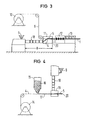
- FIG. 2 shows an enlarged cross section through the layer structure of the heat-shrinkable covering according to the invention.
- the reinforcing component 6 is arranged between the surface film 4 and the cover film 5 in this case.
- the reinforcing component 6 consists of fiber material, this fiber material being formed from fiber or thread-like sections which are brought together in a disordered configuration.
- these individual reinforcing elements can be sprinkled or placed loosely on the surface film 4 during the manufacturing process.
- Another possibility for producing a reinforcement component 6 according to the invention is that the individual fiber or thread-like sections are formed together to form a fleece or felt, so that a coherent, flat reinforcement component results.
- the individual reinforcing elements can be of different lengths and have a remaining cross section.
- the reinforcing component should have an overall open-pore structure, so that it can be securely fixed between the surface film and the cover film during the manufacturing process.
- these foils either the surface film 4 or the cover film 5, heat shrinkable. But both can also consist of heat-shrinkable material.
- the surface film 4 is still not stretched before the reinforcement component is applied.
- this layer combination is further provided with an additional adhesive layer 7, a permeation barrier being able to be arranged in it or on one of its surfaces.
- FIG. 2 it is further shown that the individual threads or fibers 6.1, 6.2 and 6.3 of the reinforcing component 6, which lie approximately in the plane of the drawing, run essentially parallel to the surface film 4 with their longitudinal direction.
- the threads or fibers 6.1 to 6.6 are considerably longer are preferably 3 to 50 times longer than the thickness of the reinforcing component 6. In this way, the aforementioned "parallelism" of the longitudinal axes of the threads or fibers to the surface film 4 is already ensured in terms of the dimensions.
- the intermediate spaces of the initially “open-pore” reinforcement component 6 are filled in the final state with (not shown here) material of the surface film 4 and / or the cover film 5 or with an adhesive, so that these films result overall in a reinforced laminate.
- the surface film 4 and the cover film 5 consist of plastic material, preferably of known shrink compounds based on polyethylene or polyolefin.
- the individual reinforcement elements of the reinforcement component 6 can be made of any material, but plastic material, preferably polyethylene or polyolefin, is preferably used in crosslinked or uncrosslinked form.
- the reinforcement component 6, as can also be seen from FIG. 1, is preferably also introduced into the closure elements 2, so that these are also reinforced. If additional longitudinal rods (not shown) or the like are provided in the area of the closure elements 2, then the reinforcing component (if appropriate together with a flat film and cover film) can be wrapped around these longitudinal rods in the form of a fleece or felt layer, thereby providing a particularly tensile arrangement .
- FIG. 3 shows a first method for producing a heat-shrinkable covering according to the invention.
- a reinforcing component 6, which is already flat is used in the form of a fleece or a felt.
- This reinforcing component 6 consists of individual fibers or threads of any desired length, preferably of the length already described, which are brought together in a disordered, that is to say in an isotropic configuration, so that an initially independent flat structure is present, which can be wound up, for example, on a storage drum 10.
- This flat structure has an open-pore and self-supporting structure and can, for example, already be introduced in the extruder 11 during the coextrusion of the flat film 4 and the cover film 5 made of shrink compound.
- the surface film 4 and the cover film 5 consist of the same base material 9, which is fed to the extruder 11 via the extruder screw 18.
- the cover film 5 could also be applied in a later process step.
- another (non-shrinkable) compatible plastic material could also be used for this.
- the extruder section 8 already leaves the finished, uniform sheet-like structure with the layer structure shown in FIG. 2, if the coating with adhesive has been carried out at the same time. This is followed by calibration 12 and cooling in the cooling zone 13 to room temperature.
- the networking then takes place in the network section and then the one for impressing the shape memory required stretching or stretching (not shown).
- This method has the advantage that the connection of all layers takes place during the extrusion, so that due to the open-pore structure of the reinforcement component 6, the (still hot) surface film 4 and cover film 5 pass through the reinforcement component 6 to form an intimate connection of all Layers.
- the manufacturing process is particularly simple and safe. Due to the open-pore and loose arrangement of the individual reinforcement elements within the reinforcement component 6, which is designed as a felt or fleece, the stretching or stretching of the surface film 4 and the cover film 5 can take place together with the reinforcement component, since a corresponding movement of the individual reinforcement elements within the structure is possible. Furthermore, in this manufacturing process, the reinforcing component 6 is crosslinked together with the other two films in a single operation, provided that the threads or fibers of the nonwoven or felt material 6 consist of crosslinkable material.
- FIG. 4 explains a further variant of the manufacturing method according to the invention.
- an already extruded surface film 4 is wound on a storage drum 14 as a correspondingly wide band.
- This surface film 4 is now pulled off and guided past a feed device 15 for reinforcing elements.
- a reinforcing component formed into a fleece or felt running from a drum 10 as in FIG. 3 could be applied.
- individual fibrous or filament-shaped reinforcement elements 16 are preferably sprinkled or placed on top of uncrosslinked plastic material in a disordered configuration, so that a semifinished product 17 consisting of surface film 4 and the reinforcement elements 16 now results, with the reinforcement elements 16 either immediately or be fixed in the subsequent extruder 19.
- the longitudinal axes of the fibrous or filament-like reinforcing elements run, as is also the case with the fleece or felt-like configurations according to the invention, preferably in a direction approximately parallel to the flat film, ie they lie essentially flat on the flat film 4.
- the configuration can also be designed with a specific preferred direction (for increased tensile strength in a specific direction), the arrangement of the individual reinforcing elements 16 remaining disordered among themselves.
- the individual reinforcing elements 16 can be different from one another in terms of shape, length, cross section, material and the like, so that the most favorable for the application can be found from the multitude of possible constellations.
- the semifinished product 17 is now fed to the extruder head 19 of an extruder 18 which contains the plastic material 9 for the cover film.
- the semifinished product 17 is now provided with the cover sheet in the extrusion process, so that at the end of this extrusion device the uniform sheet-like structure 20 is obtained, which is completed in further previously described process steps such as crosslinking, expanding, cooling, etc. for shrinkable wrapping.
- the flat structure 20 is additionally provided with an adhesive layer and, if appropriate, also with a permeation barrier in expanded or non-expanded form.
- the adhesive layer preferably consists of a hot-melt adhesive known per se and, for example, an aluminum foil, preferably also with an adhesive coating, can be applied as a permeation barrier.
- This reinforcement component is in each case firmly associated with actively shrinking plastic compound of the types known per se, whereby, due to the isotropic configuration of the reinforcement component, an almost unimpeded stretching or stretching as well as a later shrinkage of the finished casing is possible, while the reinforcement properties are retained .
- the reinforcing component can be formed from stretchable or from stretchable and shrinkable and from non-stretchable individual reinforcing elements, with free movement always having to be ensured, as is the case with simple scattering or with the formation of a fleece or felt.
- reinforcement components can also be arranged one above the other, each of these reinforcement components optionally being provided with a cover film.
- the cover foils are either applied to the respective reinforcement component, but the reverse process is also possible.
- the reinforcing component can also be embedded between two cover foils. The cohesion between the individual foils, the cover foils, as well as the surface foils and the reinforcement components is achieved by welding, gluing or material penetration, so that the reinforcement component lies on, on or between the foils. It is also possible to store the reinforcing component between cover foils and only then to apply it to the surface foil, in which case the latter is preferably designed as a shrinkable component.
- the aim of the invention is an isotropy of the reinforcing component, as is the case, for example, with a nonwoven or a felt-like structure or with free scattering.
- this reinforcing component is integrated in a matrix of actively shrinking plastic material.
- Particularly suitable materials for the individual reinforcing elements are non-crosslinked polymers, such as, for example, high weight, high density polyethylene (HWHDPE) or acrylonitrile butadiene styrene polymer (ABS). If such reinforcing elements are used, then the crosslinking takes place only later when the planar structure already assembled has been crosslinked.
- HWHDPE high weight, high density polyethylene
- ABS acrylonitrile butadiene styrene polymer
- Individual threads or fibers can also be twisted or twisted together as reinforcing elements before the reinforcing component is manufactured.
Landscapes
- Engineering & Computer Science (AREA)
- Textile Engineering (AREA)
- Chemical & Material Sciences (AREA)
- Composite Materials (AREA)
- Mechanical Engineering (AREA)
- Laminated Bodies (AREA)
- Wrappers (AREA)
- Extrusion Moulding Of Plastics Or The Like (AREA)
- Nonwoven Fabrics (AREA)
- Thermotherapy And Cooling Therapy Devices (AREA)
- Compositions Of Macromolecular Compounds (AREA)
- Shaping By String And By Release Of Stress In Plastics And The Like (AREA)
- Vehicle Interior And Exterior Ornaments, Soundproofing, And Insulation (AREA)
- Details Of Garments (AREA)
Priority Applications (1)
| Application Number | Priority Date | Filing Date | Title |
|---|---|---|---|
| AT9090122979T ATE105229T1 (de) | 1990-03-08 | 1990-11-30 | Waermeschrumpfbare umhuellung. |
Applications Claiming Priority (2)
| Application Number | Priority Date | Filing Date | Title |
|---|---|---|---|
| DE4007378 | 1990-03-08 | ||
| DE4007378 | 1990-03-08 |
Publications (3)
| Publication Number | Publication Date |
|---|---|
| EP0445381A2 true EP0445381A2 (fr) | 1991-09-11 |
| EP0445381A3 EP0445381A3 (en) | 1991-11-21 |
| EP0445381B1 EP0445381B1 (fr) | 1994-05-04 |
Family
ID=6401734
Family Applications (1)
| Application Number | Title | Priority Date | Filing Date |
|---|---|---|---|
| EP90122979A Expired - Lifetime EP0445381B1 (fr) | 1990-03-08 | 1990-11-30 | Couverture thermo-rétractable |
Country Status (6)
| Country | Link |
|---|---|
| EP (1) | EP0445381B1 (fr) |
| JP (1) | JPH0741659B2 (fr) |
| AT (1) | ATE105229T1 (fr) |
| AU (1) | AU640462B2 (fr) |
| DE (1) | DE59005632D1 (fr) |
| ES (1) | ES2052140T3 (fr) |
Cited By (4)
| Publication number | Priority date | Publication date | Assignee | Title |
|---|---|---|---|---|
| EP0525519A1 (fr) * | 1991-07-22 | 1993-02-03 | RXS Kabelgarnituren Gesellschaft mit beschränkter Haftung | Feuille composite rétrécissable |
| DE19857437A1 (de) * | 1998-12-12 | 2000-06-15 | Cellpack Gmbh | Verfahren zur Herstellung einer wärmeschrumpfbaren Verbundumhüllung und nach diesem Verfahren hergestellte Verbundumhüllung |
| EP1209402A1 (fr) * | 2000-11-23 | 2002-05-29 | Dätwyler AG Schweizerische Kabel-, Gummi- und Kunststoffwerke | Raccord de tuyaux |
| EP1211132A2 (fr) | 2000-11-29 | 2002-06-05 | Robert Bosch Gmbh | Dispositif et procédé pour surveiller l'environnement d'un véhicule |
Family Cites Families (5)
| Publication number | Priority date | Publication date | Assignee | Title |
|---|---|---|---|---|
| DE1704517A1 (de) * | 1968-01-03 | 1971-01-28 | Bemberg Ag | Verbundfolie mit einer aus einem gitterfoermigen Flaechengebilde bestehenden Verstaerkungseinlage |
| DE3707433A1 (de) * | 1987-03-07 | 1988-09-15 | Albert Stewing | Kabelmuffe |
| ES2067462T3 (es) * | 1987-10-31 | 1995-04-01 | Kabelmetal Electro Gmbh | Objeto termocontraible para recubrir un substrato. |
| DE3737005A1 (de) * | 1987-10-31 | 1989-05-11 | Kabelmetal Electro Gmbh | Waermeschrumpfender gegenstand und verfahren zu seiner herstellung |
| EP0471892B1 (fr) * | 1990-08-20 | 1995-10-18 | RXS Kabelgarnituren Gesellschaft mit beschränkter Haftung | Couverture composite comprenant au moins une feuille renforcée, thermo-rétractable, et son procédé de fabrication |
-
1990
- 1990-11-30 EP EP90122979A patent/EP0445381B1/fr not_active Expired - Lifetime
- 1990-11-30 AT AT9090122979T patent/ATE105229T1/de not_active IP Right Cessation
- 1990-11-30 ES ES90122979T patent/ES2052140T3/es not_active Expired - Lifetime
- 1990-11-30 DE DE59005632T patent/DE59005632D1/de not_active Expired - Fee Related
-
1991
- 1991-03-06 JP JP3040012A patent/JPH0741659B2/ja not_active Expired - Lifetime
- 1991-03-07 AU AU72718/91A patent/AU640462B2/en not_active Ceased
Cited By (6)
| Publication number | Priority date | Publication date | Assignee | Title |
|---|---|---|---|---|
| EP0525519A1 (fr) * | 1991-07-22 | 1993-02-03 | RXS Kabelgarnituren Gesellschaft mit beschränkter Haftung | Feuille composite rétrécissable |
| DE19857437A1 (de) * | 1998-12-12 | 2000-06-15 | Cellpack Gmbh | Verfahren zur Herstellung einer wärmeschrumpfbaren Verbundumhüllung und nach diesem Verfahren hergestellte Verbundumhüllung |
| WO2000035661A1 (fr) * | 1998-12-12 | 2000-06-22 | Cellpack Gmbh | Procede de production d'une gaine composite thermoretractable, et gaine composite produite selon ce procede |
| DE19857437B4 (de) * | 1998-12-12 | 2005-07-21 | Cellpack Gmbh | Verfahren zur Herstellung einer wärmeschrumpfbaren Verbundumhüllung und nach diesem Verfahren hergestellte Verbundumhüllung |
| EP1209402A1 (fr) * | 2000-11-23 | 2002-05-29 | Dätwyler AG Schweizerische Kabel-, Gummi- und Kunststoffwerke | Raccord de tuyaux |
| EP1211132A2 (fr) | 2000-11-29 | 2002-06-05 | Robert Bosch Gmbh | Dispositif et procédé pour surveiller l'environnement d'un véhicule |
Also Published As
| Publication number | Publication date |
|---|---|
| AU640462B2 (en) | 1993-08-26 |
| ATE105229T1 (de) | 1994-05-15 |
| JPH0741659B2 (ja) | 1995-05-10 |
| ES2052140T3 (es) | 1994-07-01 |
| DE59005632D1 (de) | 1994-06-09 |
| EP0445381B1 (fr) | 1994-05-04 |
| EP0445381A3 (en) | 1991-11-21 |
| JPH0596595A (ja) | 1993-04-20 |
| AU7271891A (en) | 1991-09-12 |
Similar Documents
| Publication | Publication Date | Title |
|---|---|---|
| DE3715681C2 (de) | Verfahren und Vorrichtung zur Herstellung eines kabelförmigen Kunststoff-Verbundkörpers | |
| DE69702706T2 (de) | Ausziehbarer gegenstand | |
| DE3508941C2 (fr) | ||
| DE3686404T2 (de) | Flexibles aus verschiedenen bestandteilen zusammengesetztes material und verfahren zu dessen herstellung. | |
| EP0350732B1 (fr) | Câble formé, élité | |
| DE7328881U (de) | Netz aus polymeren werkstoffen | |
| DE2528991A1 (de) | Element unbestimmter laenge mit optischer faser | |
| DE1804947A1 (de) | Tuchartiges,nichtgewebtes Fabrikat und Verfahren zu seiner Herstellung | |
| DE68902483T2 (de) | Verfahren und anlage zur herstellung eines bandes, das aus mindestens einem garn besteht, das mit einem thermoplastischen polymer impraegniert ist. | |
| EP0445381B1 (fr) | Couverture thermo-rétractable | |
| DE2834924C2 (de) | Verfahren zur Herstellung eines dicken, verstärkten Kunststoffgegenstands | |
| DE69906601T2 (de) | Verfahren und Vorrichtung zur simultanen Aufwicklung von mehreren vorimprägnierten Fasersträngen auf einen Kern und so hergestellte Verbundwerkstoffstrukturen | |
| EP0471892B1 (fr) | Couverture composite comprenant au moins une feuille renforcée, thermo-rétractable, et son procédé de fabrication | |
| DE69624595T2 (de) | Drahtvorformlinge für verbundstoffherstellung und verfahren zu dessen herstellung | |
| DE2709484C2 (de) | Verfahren zur Herstellung von Röhrchenhüllen für Röhrchenelektroden von Akkumulatoren und Vorrichtung hierfür | |
| DE102019219073A1 (de) | Verfahren zur additiven Fertigung eines Werkstücks mittels Schmelzschichtung, sowie faserverstärktes Werkstück | |
| DE2547547A1 (de) | Verfahren zur herstellung von rohr- oder schlauchleitungen aus kunstharz-verbundmaterial und derartige leitungen | |
| DE102016007464A1 (de) | Verstärkungsstreifen für ein rohrförmiges bauteil aus verbundmaterial | |
| DE69314905T2 (de) | Verfahren zum Herstellen von rohrförmigen Elementen aus kunstharzgebundenen Fasern, die ineinanderschiebbar sind, um eine Angelrute mit kontrollierter Bewegung zu bilden, und mit diesem Verfahren hergestellte Elemente | |
| DE3737005A1 (de) | Waermeschrumpfender gegenstand und verfahren zu seiner herstellung | |
| DE2433276B2 (de) | Verfahren zur Herstellung von Armierungsbändern aus glasfaserverstärktem Kunststoff | |
| DE2913054C2 (fr) | ||
| EP0570997A1 (fr) | Procédé de fabrication de bande thermorétractable en matière synthétique | |
| DE2236286C3 (de) | Vliesstoffverstärktes Papier mit einer Verstärkung aus einem offenen Netzwerk | |
| EP0314907B1 (fr) | Article rétractable à chaud |
Legal Events
| Date | Code | Title | Description |
|---|---|---|---|
| PUAI | Public reference made under article 153(3) epc to a published international application that has entered the european phase |
Free format text: ORIGINAL CODE: 0009012 |
|
| 17P | Request for examination filed |
Effective date: 19901220 |
|
| AK | Designated contracting states |
Kind code of ref document: A2 Designated state(s): AT BE CH DE ES FR GB GR IT LI NL SE |
|
| PUAL | Search report despatched |
Free format text: ORIGINAL CODE: 0009013 |
|
| AK | Designated contracting states |
Kind code of ref document: A3 Designated state(s): AT BE CH DE ES FR GB GR IT LI NL SE |
|
| 17Q | First examination report despatched |
Effective date: 19930510 |
|
| GRAA | (expected) grant |
Free format text: ORIGINAL CODE: 0009210 |
|
| AK | Designated contracting states |
Kind code of ref document: B1 Designated state(s): AT BE CH DE ES FR GB GR IT LI NL SE |
|
| REF | Corresponds to: |
Ref document number: 105229 Country of ref document: AT Date of ref document: 19940515 Kind code of ref document: T |
|
| REF | Corresponds to: |
Ref document number: 59005632 Country of ref document: DE Date of ref document: 19940609 |
|
| REG | Reference to a national code |
Ref country code: ES Ref legal event code: FG2A Ref document number: 2052140 Country of ref document: ES Kind code of ref document: T3 |
|
| ITF | It: translation for a ep patent filed | ||
| GBT | Gb: translation of ep patent filed (gb section 77(6)(a)/1977) |
Effective date: 19940711 |
|
| ET | Fr: translation filed | ||
| REG | Reference to a national code |
Ref country code: GR Ref legal event code: FG4A Free format text: 3012534 |
|
| EAL | Se: european patent in force in sweden |
Ref document number: 90122979.9 |
|
| PLBE | No opposition filed within time limit |
Free format text: ORIGINAL CODE: 0009261 |
|
| STAA | Information on the status of an ep patent application or granted ep patent |
Free format text: STATUS: NO OPPOSITION FILED WITHIN TIME LIMIT |
|
| 26N | No opposition filed | ||
| PGFP | Annual fee paid to national office [announced via postgrant information from national office to epo] |
Ref country code: GR Payment date: 19991027 Year of fee payment: 10 |
|
| PGFP | Annual fee paid to national office [announced via postgrant information from national office to epo] |
Ref country code: AT Payment date: 19991109 Year of fee payment: 10 |
|
| PGFP | Annual fee paid to national office [announced via postgrant information from national office to epo] |
Ref country code: GB Payment date: 19991116 Year of fee payment: 10 |
|
| PGFP | Annual fee paid to national office [announced via postgrant information from national office to epo] |
Ref country code: SE Payment date: 19991118 Year of fee payment: 10 Ref country code: ES Payment date: 19991118 Year of fee payment: 10 |
|
| PGFP | Annual fee paid to national office [announced via postgrant information from national office to epo] |
Ref country code: NL Payment date: 19991122 Year of fee payment: 10 |
|
| PGFP | Annual fee paid to national office [announced via postgrant information from national office to epo] |
Ref country code: BE Payment date: 19991123 Year of fee payment: 10 |
|
| PGFP | Annual fee paid to national office [announced via postgrant information from national office to epo] |
Ref country code: FR Payment date: 19991126 Year of fee payment: 10 |
|
| PGFP | Annual fee paid to national office [announced via postgrant information from national office to epo] |
Ref country code: DE Payment date: 20000121 Year of fee payment: 10 |
|
| PGFP | Annual fee paid to national office [announced via postgrant information from national office to epo] |
Ref country code: CH Payment date: 20000214 Year of fee payment: 10 |
|
| PG25 | Lapsed in a contracting state [announced via postgrant information from national office to epo] |
Ref country code: LI Free format text: LAPSE BECAUSE OF NON-PAYMENT OF DUE FEES Effective date: 20001130 Ref country code: GR Free format text: LAPSE BECAUSE OF NON-PAYMENT OF DUE FEES Effective date: 20001130 Ref country code: GB Free format text: LAPSE BECAUSE OF NON-PAYMENT OF DUE FEES Effective date: 20001130 Ref country code: CH Free format text: LAPSE BECAUSE OF NON-PAYMENT OF DUE FEES Effective date: 20001130 Ref country code: BE Free format text: LAPSE BECAUSE OF NON-PAYMENT OF DUE FEES Effective date: 20001130 Ref country code: AT Free format text: LAPSE BECAUSE OF NON-PAYMENT OF DUE FEES Effective date: 20001130 |
|
| PG25 | Lapsed in a contracting state [announced via postgrant information from national office to epo] |
Ref country code: SE Free format text: LAPSE BECAUSE OF NON-PAYMENT OF DUE FEES Effective date: 20001201 Ref country code: ES Free format text: LAPSE BECAUSE OF NON-PAYMENT OF DUE FEES Effective date: 20001201 |
|
| BERE | Be: lapsed |
Owner name: RXS SCHRUMPFTECHNIK-GARNITUREN G.M.B.H. Effective date: 20001130 |
|
| PG25 | Lapsed in a contracting state [announced via postgrant information from national office to epo] |
Ref country code: NL Free format text: LAPSE BECAUSE OF NON-PAYMENT OF DUE FEES Effective date: 20010601 |
|
| REG | Reference to a national code |
Ref country code: CH Ref legal event code: PL |
|
| GBPC | Gb: european patent ceased through non-payment of renewal fee |
Effective date: 20001130 |
|
| PG25 | Lapsed in a contracting state [announced via postgrant information from national office to epo] |
Ref country code: FR Free format text: LAPSE BECAUSE OF NON-PAYMENT OF DUE FEES Effective date: 20010731 |
|
| NLV4 | Nl: lapsed or anulled due to non-payment of the annual fee |
Effective date: 20010601 |
|
| PG25 | Lapsed in a contracting state [announced via postgrant information from national office to epo] |
Ref country code: DE Free format text: LAPSE BECAUSE OF NON-PAYMENT OF DUE FEES Effective date: 20010801 |
|
| EUG | Se: european patent has lapsed |
Ref document number: 90122979.9 |
|
| REG | Reference to a national code |
Ref country code: FR Ref legal event code: ST |
|
| REG | Reference to a national code |
Ref country code: ES Ref legal event code: FD2A Effective date: 20011214 |
|
| PG25 | Lapsed in a contracting state [announced via postgrant information from national office to epo] |
Ref country code: IT Free format text: LAPSE BECAUSE OF NON-PAYMENT OF DUE FEES;WARNING: LAPSES OF ITALIAN PATENTS WITH EFFECTIVE DATE BEFORE 2007 MAY HAVE OCCURRED AT ANY TIME BEFORE 2007. THE CORRECT EFFECTIVE DATE MAY BE DIFFERENT FROM THE ONE RECORDED. Effective date: 20051130 |