EP0445447A1 - Positionsanweisender Apparat - Google Patents
Positionsanweisender Apparat Download PDFInfo
- Publication number
- EP0445447A1 EP0445447A1 EP90302361A EP90302361A EP0445447A1 EP 0445447 A1 EP0445447 A1 EP 0445447A1 EP 90302361 A EP90302361 A EP 90302361A EP 90302361 A EP90302361 A EP 90302361A EP 0445447 A1 EP0445447 A1 EP 0445447A1
- Authority
- EP
- European Patent Office
- Prior art keywords
- detectors
- output
- array
- image
- detector
- Prior art date
- Legal status (The legal status is an assumption and is not a legal conclusion. Google has not performed a legal analysis and makes no representation as to the accuracy of the status listed.)
- Withdrawn
Links
Images

Classifications
-
- B—PERFORMING OPERATIONS; TRANSPORTING
- B07—SEPARATING SOLIDS FROM SOLIDS; SORTING
- B07C—POSTAL SORTING; SORTING INDIVIDUAL ARTICLES, OR BULK MATERIAL FIT TO BE SORTED PIECE-MEAL, e.g. BY PICKING
- B07C5/00—Sorting according to a characteristic or feature of the articles or material being sorted, e.g. by control effected by devices which detect or measure such characteristic or feature; Sorting by manually actuated devices, e.g. switches
- B07C5/04—Sorting according to size
- B07C5/10—Sorting according to size measured by light-responsive means
-
- B—PERFORMING OPERATIONS; TRANSPORTING
- B07—SEPARATING SOLIDS FROM SOLIDS; SORTING
- B07C—POSTAL SORTING; SORTING INDIVIDUAL ARTICLES, OR BULK MATERIAL FIT TO BE SORTED PIECE-MEAL, e.g. BY PICKING
- B07C5/00—Sorting according to a characteristic or feature of the articles or material being sorted, e.g. by control effected by devices which detect or measure such characteristic or feature; Sorting by manually actuated devices, e.g. switches
- B07C5/04—Sorting according to size
- B07C5/12—Sorting according to size characterised by the application to particular articles, not otherwise provided for
- B07C5/122—Sorting according to size characterised by the application to particular articles, not otherwise provided for for bottles, ampoules, jars and other glassware
- B07C5/126—Sorting according to size characterised by the application to particular articles, not otherwise provided for for bottles, ampoules, jars and other glassware by means of photo-electric sensors, e.g. according to colour
-
- G—PHYSICS
- G06—COMPUTING OR CALCULATING; COUNTING
- G06T—IMAGE DATA PROCESSING OR GENERATION, IN GENERAL
- G06T7/00—Image analysis
- G06T7/70—Determining position or orientation of objects or cameras
Definitions
- the present invention relates to an optical system for viewing an object and for detecting certain aspects relating thereto such as the extent of its dimensions in two directions.
- containers such as bottles having irregular shapes often have labels fastened thereon which also may be of irregular shape and it is desirable to be able to determine that the label is in a proper position with respect to the bottle.
- One way of determining whether the label is in the correct position is to observe the bottle and the label with a plurality of radiation responsive detectors which will produce individual outputs dependent upon whether the bottle or the label is in the field of view with respect to a background.
- bottles with labels affixed thereto have been moved along a conveyor belt so as to pass a linear array of detectors which are mounted adjacent the conveyor belt, usually perpendicular to the bottle motion.
- the image of the moving bottle is directed on to the detectors so that the outputs of the detectors will change when the bottle comes into the field of view and then change again when the label comes into the field of view, thus giving a one-dimensional indication of the extent of the bottle and label because the detectors, being spaced vertically, will be activated by the bottle and the label so that it can be determined from the number of detectors that are activated, what the vertical dimensions of the bottle and label are.
- the conveyor belt may be controlled to move at a predetermined rate so that the position of the bottle is known from its initial placement on the conveyor belt and by timing the speed of the conveyor belt as it moves past the detector array.
- the bottle may slip with respect to the conveyor belt and thus throw all of the measurements off.
- the photo cell systems different size bottles require that the photo electric detectors be repositioned for each different size in order to now provide the proper position signals.
- the present invention overcomes the problems of the prior art by providing a detector array not only in a single direction such as vertical, but also in a second direction such as horizontal.
- the terms “vertical” and “horizontal” are relative terms with respect to any application since the height measurement of the bottle need not always be vertical, nor need the position be measured in a horizontal direction. All that is actually needed is that the first and second directions through which the measurements are to be taken be coordinated in a known manner with respect to the direction of movement of the bottle.
- the computer can be programmed to detect and account for the changes in dimensions and orientations and perhaps different selected outputs used to trigger desired readings, the result is an accurate output for a large variety of applications without changing detector positions or checking for slippage.
- a linear array mirror system in which a single linear array of detectors are arranged with respect to a plurality of mirrors so that measurements can be taken in more than one direction at the same time.
- Such an array of detectors is ideal for application in the present invention although it should be understood that two separate detector arrays located at a desired angle with respect to each other may also be utilized. Also, certain detectors of a two-dimensional array may be utilized.
- FIGURES 1-6 the image of bottle 10 having a label 12 affixed thereto is seen moving to the right as shown by arrow 14.
- the image of bottle 10 may be produced by an optical system similar to that shown in the above-mentioned co-pending application or by other common means and need not be further described here.
- the bottle and label are both of irregular shape and that the label is placed on the bottle in a skew position. This is the presumed desired position for the label which the present invention is intended to assure.
- a first linear array of detectors 20 identified by letters A-I which are shown equally spaced along a horizontal axis parallel to the direction of movement 14 of bottle 10.
- a second linear array of detectors 22 identified by letters K-W are shown equally spaced along a vertical axis perpendicular to the direction of movement 14 of bottle 10. It is noted that the center detector C is a part of both detector arrays, but, if desired, the two arrays could be offset and a detector Q (not shown) used in the second array. It should be understood that the number of detectors in each array is a matter of choice and it is common to use 256 detectors in each of the arrays. Only a few detectors are shown herein to simplify the explanation.
- FIGURES 1-6 are perpendicular to each other and lie along the vertical and horizontal axes, such arrangement is arbitrary and the position of the two arrays may be chosen so as to lie at any angle with respect to each other for particular purposes with neither direction being “horizontal” or “vertical”.
- the detectors of each array may be of any standard variety, but in the preferred embodiment, CCD detectors are used and the output of each detector changes as it goes from sensing a background to sensing the image of bottle 10 and then again changes when sensing the image of label 12.
- the level of energy received by each detector is indicative of whether or not it is receiving radiation from the background, from the bottle, or from the label. This is desirable in order for the apparatus to be able to determine the position and extent of the bottle and label individually.
- detector A in array 20 has just been eclipsed by the image of bottle 10 while all of the other detectors are receiving energy from the background. Accordingly, the output of detector A will change and, as will be described in connection with FIGURES 6 and 7, may operate to produce a signal which turns the rest of the detectors to an "on" or sensing condition, thus saving energy and allowing the system to be self-activated in contra distinction with the prior art which had to be separately synchronized for each object being sensed and remained constantly on.
- the detector arrays 20 and 22 will be self-activated and, as the bottle and label move to the right as shown in FIGURES 2-6, the outputs of the detectors will change in a way which will be indicative of the position of the label and bottle with respect to the detector arrays.
- the image of bottle 10 has moved to the right far enough so that the leading edge 26 of bottle 10 has just passed detector C in array 20 and is thus eclipsing detectors N-U in array 22.
- the signal from detector C may be used to alert the system to the fact that the vertical dimension of bottle 10 may be measured. That is, an output from detector C may produce a "valid entry" signal as will be explained in connection with FIGURES 7 and 8.
- the height of bottle 10 at position C is determined from the fact that the 8 equally spaced detectors N-U have been eclipsed. Of course, equal spacing of the detectors, while most convenient, is not an absolute requirement for proper operation so long as the signal analyzing equipment can determine the extent of a dimension by the number of detectors which are eclipsed.
- a downstream computer receives the knowledge of the position of the bottle by virtue of the difference in output between detectors C and D in array 20 and receives a height indication by virtue of the difference in output between detectors M and N and detectors U and V of array 22, i.e., 8 units. Accordingly, the computer will begin to know what type of bottle is being encountered and, as more information is gathered, will be able to determine whether or not this or some other kind of bottle or other object is being encountered.
- detectors A and B are now eclipsed by the image of label 12 and, accordingly, the computer will know that the label 12 has been encountered and that its leading edge 28 lies between positions B and C. This provides the computer with information as to the starting position of label 12 which it may then use to determine whether or not the starting position is correct or not.
- bottle image 10 has moved to a position where leading edge 26 has moved between detectors D and E of array 20 and the leading edge 28 of label 12 has moved to a position between detectors C and D of array 20 and is thus eclipsing detectors P-R in array 22.
- detector M in array 22 is now eclipsed by bottle 10 and accordingly, if the output of detector D is used to trigger a "valid entry" reading, the computer will know that at the position between detectors D and E of array 20, the bottle has a height equal to between 8 and 9 units and that label 12 has a height equal to between 3 and 4 units. Accordingly, the computer may use this to determine the orientation of the label 12 with respect to bottle 10 and has more information to determine whether the bottle is the correct one being observed.
- FIGURE 4 the bottle has moved to a generally central position with respect to array 22 and the leading edge 26 is now eclipsing detector E while detectors L-U are being eclipsed by bottle 10 and detectors O-R are still being eclipsed by label 12. Accordingly, if the output of detector E is used to trigger a "valid entry" reading, the computer will know the position of peak 30 of label 12 in its movement to the right. This too will provide information to the computer determining the correct position of the label and the identification of the label and bottle. It should also be noted that detector A is no longer being eclipsed by label 12 which provides the computer with information as to the position of the trailing edge 32 of label 12. Combining this information with the position of the leading edge 28 of label 12, the computer will know the horizontal dimension of label 12 as is desired.
- FIGURE 5 the image of bottle 10 has now moved to where the leading edge 26 of bottle 10 lies between detectors F and G of array 20. It should also be noted that the trailing edge 36 of bottle 10 has just passed beyond detector A of array 20 and, accordingly, if the output of detector F is used to trigger a "valid entry" reading, the computer will know that the horizontal dimension of bottle 10 is between 5 and 6 units. This then can be used as further evidence of the identity of the bottle and the correct positioning of label 12. It will be noted that in the position shown in FIGURE 5, detectors P-S are now eclipsed by label 12 and, accordingly, the computer will know that the vertical dimension of label 12 has changed downwardly to provide desired information as to the label shape.
- FIGURE 6 the image of bottle 10 has now moved to a position where it has left the entire vertical array 22 and now eclipses detectors D-H in array 20. All of the information needed to determine the size and shape of bottle 10 has been fed to the computer since the detectors in the vertical array 22 have been producing outputs which vary with the vertical dimension as it moves along the direction of arrow 14. Furthermore, the horizontal information concerning the size of bottle 10 and label 12 has been determined in a similar fashion. Thus it can be determined from a programming of a computer that label 12 is in fact in the correct position on bottle 10 and that bottle 10 and label 12 are of a desired type.
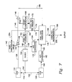
- FIGURE 7 a schematic block diagram of the present invention is disclosed.
- the horizontal array of detectors 20 of FIGURES 1-6 is shown as a box 120 labelled “CCD1” and the vertical array of detector 22 of FIGURES 1-6 is shown as a box 122 labelled “CCD2".
- the output of the individual detectors or "pixels" in array 120 is produced in serial fashion on an output line 126 which is presented to the positive input terminal of a comparator 128 and also by a line 130 to an A/D converter 132 which produces a digital output signal on a line 134 to a pixel data processor 136.
- comparator 128 is connected by a line 140 to an output of a pixel threshold value generator 142.
- pixel threshold value generator 142 is to provide an input to comparator 128 of magnitude indicative of the size of the signal above which the output of CCD array 120 must rise before comparator 128 produces an output on a line 146.
- comparator 128 For example, if the value of the background radiation in the system being used has a certain value, the negative input of comparator 128 would be set to be somewhat above the background value so that while CCD array 120 was viewing only the background, there would be no output from comparator 128, but when the image of the bottle 10 of FIGURES 1-6 first comes into view by the CCD array 120, one or more of the detectors will produce an output greater than the background value and thus comparator 128 will produce an output on line 146 to the upper input of an AND gate 148. Of course, if the background was light and the bottle were dark, the reverse could be true, and the output from the CCD array 120 would be high when it was viewing background and drop to a low value when the image of the bottle was encountered.
- the output of comparator 128 will change and, in the present example, will increase to a high value when the image of the bottle comes into view.
- the AND gate 148 will first receive a single pulse from detector A and, later, receive a pulse from both pixels A and B, etc.
- a clock 150 is shown in FIGURE 7 operating through a line 152 and lines 154 and 156 to drive CCD arrays 120 and 122, respectively.
- a signal from clock 150 causes the output of the detectors in array 120 to appear on line 126 in periodic fashion.
- Clock 150 has a second output on a line 160 shown connected to a pixel number counter 162 whose purpose is to produce an output on a connection 164 continuously indicative of the pixel output from the CCD array 120. More particularly, the output of pixel number counter 162 on line 164 is presented to a count comparator device 168 to tell the count comparator device 168 which pixel is being outputted from the CCD array 120 at the present time.
- Count comparator 168 receives a second input over a line 170 from a pixel number trigger 172.
- Pixel number trigger 172 receives an input over a line 174 and a line 176 from the pixel data processor 136.
- the pixel data processor is programmed to tell the pixel number trigger 172 when it desires to have "valid data" received from the CCD arrays 120 and 122. Accordingly, pixel number trigger 172 may receive, for example, a signal over lines 176 and 174 indicating that when the bottle image of FIGURES 1-6 reaches the third position, i.e., pixel C, a "valid data" reading should be taken of both CCD array 120 and CCD array 122.
- pixel number trigger 172 provides a signal over line 170 to the count comparator 168 telling count comparator 168 to produce an output on a line 180 whenever the third pixel (pixel C) is producing an output on line 126, i.e., the situation seen in FIGURE 2. Therefore, every time the interrogation of the pixels in CCD array 120 repeats, a positive pulse will appear on line 180 as the output of pixel C is emerging from CCD array 120.
- the actual number of individual CCD elements in the array is normally 256 and, accordingly, it might be pixel number 80 in a practical system that would be interrogated to determine when valid data should be taken.
- This pulse tells the pixel data processor 136 that the image of the bottle has reached the desired location and that the data being submitted by the arrays 120 and 122 is now "valid" and should be stored. Accordingly, the data from the CCD array 120 will pass along lines 126 and 130 through the A/D converter 132 and line 134 to the pixel data processor 136 where it will be stored. Likewise, the output from CCD array 122 appearing on a line 190 through and A/D converter 192 and a line 194 will also be stored. Accordingly, the pixel data processor 136 now has knowledge of what the vertical array of detectors 22 are detecting when the position of the image is just past pixel number C as was the case in FIGURE 2. Thus, the vertical data will be indicative that pixels N-U of FIGURE 2 are receiving signals greater than the background while pixels C, B, and A of the horizontal array 120 are receiving signals greater than the background.
- the pixel data processor 136 will now determine where the next "valid data" reading should be taken, for example, when pixel number D in the horizontal array 120 has just gone from background to bottle image as in FIGURE 3. Accordingly, pixel data processor 136 will produce a signal on line 176 and 174 to the pixel number trigger box 172 to supply a signal on line 170 indicating that the fourth pixel (pixel D) should now be interrogated. Now, when the count comparator detects the fourth pixel from pixel number counter 162, a pulse will appear on line 180.
- AND gate 148 will receive simultaneous inputs on lines 146 and 180 to produce a second "valid data” output on line 186 telling pixel data processor 136 that the desired situation has now been reached and it should store the outputs from the individual pixels of CCD arrays 120 and 122.
- the pixel data processor continually updating the pixel number trigger 172 to take readings at different positions in the travel of the bottle in the horizontal direction in FIGURES 1-6. This will continue until there is no longer any need for further data at which time the pixel data processor will reset the pixel number trigger 172 so that no output is received from the count comparator 168 during the following cycles. Meanwhile, the pixel data processor 136 will produce an output on a line 196 indicative of the stored values and will present them to a computed measurements box 198 which will cause the required calculations to be made to determine if the bottle and its label are in the proper position.
- computed measurements box 198 will compare the signals generated by the pixels in arrays 120 and 122 with the desired information previously held in memory for that particular bottle/label arrangement and will produce an output on line 200 indicating "OK” if the bottle and label have met the proper specifications or will produce an output "NOT OK” if the bottle and label have failed to meet the specifications.
- Computed measurements box 198 may be a part of the pixel data processor 136 in a normal system.
- pixel data processor 136 may send a signal over lines 176 and 204 to the pixel threshold value generator 142 so that comparator 128 will now produce outputs indicative of the changed situation. Likewise, in such event, the output from the pixel data processor 136 on line 196 will tell the computed measurements device 198 which set of values in its memory should be compared with the next set of outputs therefrom.
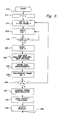
- FIGURE 8 shows the logic diagram for programming the computer to perform the functions described above.
- the output of box 212 is therefore presented to a box 214 labelled "set P n & X for frame F” which sets the pixel number corresponding to frame 0 and also sets the threshold value for that pixel to exceed in order to produce an output.
- box 214 would determine that the third pixel (pixel C) is to be interrogated for frame 0 and that for it to be a "valid data" signal, it must exceed the value which is presented on line 204 to the pixel threshold value generator 142 of FIGURE 7.
- Box 216 then checks the input from CCD1 and a diamond-shaped box 218 asks the question whether or not the voltage of the predetermined pixel, V P N, is greater than the threshold value X or not. If “no", a signal is then presented back to the box 216 to check the output of CCD1 again. As soon as the value of voltage V P N does exceed the value X, then a "yes" signal is presented from box 218 to box 220 labelled input CCD2 calling for the release and storage of information from the CCD1 and CCD2 to the pixel data processor 136 of FIGURE 7.
- a signal is sent back up to box number 214 which sets the pixel number and threshold value for the next frame, i.e., frame number 1. This will continue until all the frames have been interrogated at which time the output from decision box 228 will be "no" which will be presented to a combined frame measurements box 230 which will look at all of the values that have been stored at the various frame readings and will provide a signal indicative thereof to a make inspection decisions box 232 where the frame measurements are compared with the desired frame measurements to produce an output to a box 234 indicative of whether or not the bottle and the label have met the required measurements.
- the final output from output results box 234 is presented on a line 236 for the operator or some decision-making machine to determine whether the bottle under examination is satisfactory or not.
Landscapes
- Engineering & Computer Science (AREA)
- Computer Vision & Pattern Recognition (AREA)
- Physics & Mathematics (AREA)
- General Physics & Mathematics (AREA)
- Theoretical Computer Science (AREA)
- Length Measuring Devices By Optical Means (AREA)
Applications Claiming Priority (1)
| Application Number | Priority Date | Filing Date | Title |
|---|---|---|---|
| US07/202,074 US4912337A (en) | 1988-06-03 | 1988-06-03 | Position responsive apparatus |
Publications (1)
| Publication Number | Publication Date |
|---|---|
| EP0445447A1 true EP0445447A1 (de) | 1991-09-11 |
Family
ID=22748400
Family Applications (1)
| Application Number | Title | Priority Date | Filing Date |
|---|---|---|---|
| EP90302361A Withdrawn EP0445447A1 (de) | 1988-06-03 | 1990-03-06 | Positionsanweisender Apparat |
Country Status (2)
| Country | Link |
|---|---|
| US (1) | US4912337A (de) |
| EP (1) | EP0445447A1 (de) |
Cited By (2)
| Publication number | Priority date | Publication date | Assignee | Title |
|---|---|---|---|---|
| WO2000043757A1 (fr) * | 1999-01-19 | 2000-07-27 | Visiglas Societe Anonyme | Procede et dispositif pour detecter des glacures dans des pieces en matiere translucide ou transparente |
| CN1063722C (zh) * | 1994-04-13 | 2001-03-28 | 专利工业建设协会 | 具有纱线退绕制动器的纱线存放器 |
Families Citing this family (13)
| Publication number | Priority date | Publication date | Assignee | Title |
|---|---|---|---|---|
| JPH0312106U (de) * | 1989-06-21 | 1991-02-07 | ||
| IT1239090B (it) * | 1990-01-17 | 1993-09-21 | Alfa Costr Mecc Spa | Dispositivo di presa di bottiglie e di supporto per un sistema di lettura per il centraggio delle bottiglie,in macchina etichettatrice. |
| US5347275A (en) * | 1991-10-03 | 1994-09-13 | Lau Clifford B | Optical pointer input device |
| US5302948A (en) * | 1991-10-03 | 1994-04-12 | Lau Clifford B | Object pointer computer input apparatus |
| US5212392A (en) * | 1991-12-13 | 1993-05-18 | General Electric Company | Optical sensing apparatus for detecting linear displacement of an object and method of operation thereof with detector matrix and centroid detection |
| EP0770849A3 (de) * | 1995-10-23 | 1998-10-14 | Peter Lisec | Vorrichtung zum Ermitteln der Form von tafelförmigen Gegenständen |
| DE19541977A1 (de) * | 1995-11-10 | 1997-05-15 | Bielomatik Leuze & Co | Einrichtung zur Verarbeitung von Lagenmaterial |
| DE19911074B4 (de) * | 1999-03-12 | 2005-11-10 | Khs Maschinen- Und Anlagenbau Ag | Vorrichtung zum Etikettieren von Flaschen mit einem Etikettieraggregat |
| US8077051B2 (en) * | 2008-01-18 | 2011-12-13 | Sensors Incorporated | Fault detection system with redundant product teach verification |
| US9147326B2 (en) | 2008-01-18 | 2015-09-29 | Sensors Incorporated | Encoder based speed compensated reject system and method |
| US10198653B2 (en) | 2017-04-26 | 2019-02-05 | Sensors Incorporated | System and method for performing production line product identification |
| US11908122B2 (en) | 2017-04-26 | 2024-02-20 | Sensors Incorporated | System and method for performing production line product identification |
| DE102017121891A1 (de) * | 2017-09-21 | 2019-03-21 | Sick Ag | Optoelektronischer Sensor und Verfahren zur Erfassung von transparenten Objekten |
Citations (3)
| Publication number | Priority date | Publication date | Assignee | Title |
|---|---|---|---|---|
| FR2400969A1 (fr) * | 1977-08-24 | 1979-03-23 | Hugin Kassaregister Ab | Appareil d'identification et d'enregistrement de bouteilles |
| GB1571836A (en) * | 1977-01-31 | 1980-07-23 | Barry Wehmiller Co | Electronic image analyzer method and apparatus |
| US4678920A (en) * | 1985-06-17 | 1987-07-07 | General Motors Corporation | Machine vision method and apparatus |
Family Cites Families (4)
| Publication number | Priority date | Publication date | Assignee | Title |
|---|---|---|---|---|
| FR1204531A (fr) * | 1958-04-14 | 1960-01-26 | Oreal | Détergents anion-actifs anhydres sous forme d'aérosols |
| US3529169A (en) * | 1967-12-06 | 1970-09-15 | Fmc Corp | Photoelectric apparatus for detecting shape of bottles |
| US3955179A (en) * | 1971-12-14 | 1976-05-04 | Tore Planke | Apparatus for automatic pattern recognition and registration of empty bottles |
| US4259571A (en) * | 1979-05-25 | 1981-03-31 | The Mead Corporation | Apparatus and method for container recognition |
-
1988
- 1988-06-03 US US07/202,074 patent/US4912337A/en not_active Expired - Lifetime
-
1990
- 1990-03-06 EP EP90302361A patent/EP0445447A1/de not_active Withdrawn
Patent Citations (3)
| Publication number | Priority date | Publication date | Assignee | Title |
|---|---|---|---|---|
| GB1571836A (en) * | 1977-01-31 | 1980-07-23 | Barry Wehmiller Co | Electronic image analyzer method and apparatus |
| FR2400969A1 (fr) * | 1977-08-24 | 1979-03-23 | Hugin Kassaregister Ab | Appareil d'identification et d'enregistrement de bouteilles |
| US4678920A (en) * | 1985-06-17 | 1987-07-07 | General Motors Corporation | Machine vision method and apparatus |
Cited By (2)
| Publication number | Priority date | Publication date | Assignee | Title |
|---|---|---|---|---|
| CN1063722C (zh) * | 1994-04-13 | 2001-03-28 | 专利工业建设协会 | 具有纱线退绕制动器的纱线存放器 |
| WO2000043757A1 (fr) * | 1999-01-19 | 2000-07-27 | Visiglas Societe Anonyme | Procede et dispositif pour detecter des glacures dans des pieces en matiere translucide ou transparente |
Also Published As
| Publication number | Publication date |
|---|---|
| US4912337A (en) | 1990-03-27 |
Similar Documents
| Publication | Publication Date | Title |
|---|---|---|
| US4912337A (en) | Position responsive apparatus | |
| US4179685A (en) | Automatic currency identification system | |
| US4446481A (en) | Automatic product inspection system | |
| TW464797B (en) | Physical distribution information reader | |
| US7248754B2 (en) | Apparatus and method for determining whether machine readable information on an item matches the item | |
| EP0178090B1 (de) | Verfahren zum Bestimmen eines Volumens | |
| US5256883A (en) | Method and system for broad area field inspection of a moving web, particularly a printed web | |
| EP0400607B1 (de) | Infrarot-Überwachungssystem | |
| EP2158500B1 (de) | Verfahren und system für optoelektronische erkennung und ortung von objekten | |
| US3814521A (en) | Object recognition | |
| EP0497477B1 (de) | Verfahren und Vorrichtung zur Inspektion des Endes eines Objektes auf Defekte | |
| US4733226A (en) | Overlapped-transfer detecting apparatus for mail article | |
| US4678920A (en) | Machine vision method and apparatus | |
| US3428817A (en) | Length measurer with plurality of photocells which are sequentially gated | |
| US4378495A (en) | Method and apparatus for setup of inspection devices for glass bottles | |
| EP1122511B1 (de) | Positionsmesssensor mit Datensichtgerät | |
| EP0293510B1 (de) | Vorrichtung zur Prüfung der Seitenwand einer Flasche | |
| EP0549736B1 (de) | Bildlesesystem | |
| WO1999049277A1 (en) | An optical sensor system for incorporation in a conveyor system and a method for determining the geometry and/or angular position of a moving object | |
| CN109848070A (zh) | 一种产品分拣系统及方法 | |
| CN1381717A (zh) | 射线检验设备和射线检验方法 | |
| WO1988008958A1 (en) | A method and arrangement for determining the size and/or the shape of a freely falling object | |
| US4499372A (en) | Mail-article tracing apparatus | |
| KR20230028659A (ko) | 작업자 안전사고 모니터링 시스템 | |
| CA2010540A1 (en) | Position responsive apparatus |
Legal Events
| Date | Code | Title | Description |
|---|---|---|---|
| PUAI | Public reference made under article 153(3) epc to a published international application that has entered the european phase |
Free format text: ORIGINAL CODE: 0009012 |
|
| AK | Designated contracting states |
Kind code of ref document: A1 Designated state(s): CH DE FR GB IT LI NL |
|
| STAA | Information on the status of an ep patent application or granted ep patent |
Free format text: STATUS: THE APPLICATION IS DEEMED TO BE WITHDRAWN |
|
| 18D | Application deemed to be withdrawn |
Effective date: 19920312 |